EP1238873A2 - Seat belt retractor - Google Patents
Seat belt retractor Download PDFInfo
- Publication number
- EP1238873A2 EP1238873A2 EP02004206A EP02004206A EP1238873A2 EP 1238873 A2 EP1238873 A2 EP 1238873A2 EP 02004206 A EP02004206 A EP 02004206A EP 02004206 A EP02004206 A EP 02004206A EP 1238873 A2 EP1238873 A2 EP 1238873A2
- Authority
- EP
- European Patent Office
- Prior art keywords
- belt
- spool
- retractor
- electric motor
- winding
- Prior art date
- Legal status (The legal status is an assumption and is not a legal conclusion. Google has not performed a legal analysis and makes no representation as to the accuracy of the status listed.)
- Granted
Links
- 238000004804 winding Methods 0.000 claims abstract description 38
- 230000007246 mechanism Effects 0.000 claims description 4
- 230000008878 coupling Effects 0.000 description 2
- 238000010168 coupling process Methods 0.000 description 2
- 238000005859 coupling reaction Methods 0.000 description 2
- 238000010586 diagram Methods 0.000 description 2
- 230000004308 accommodation Effects 0.000 description 1
- 239000003990 capacitor Substances 0.000 description 1
- 230000007423 decrease Effects 0.000 description 1
- 230000001627 detrimental effect Effects 0.000 description 1
- 230000002441 reversible effect Effects 0.000 description 1
Images


Classifications
-
- B—PERFORMING OPERATIONS; TRANSPORTING
- B60—VEHICLES IN GENERAL
- B60R—VEHICLES, VEHICLE FITTINGS, OR VEHICLE PARTS, NOT OTHERWISE PROVIDED FOR
- B60R22/00—Safety belts or body harnesses in vehicles
- B60R22/34—Belt retractors, e.g. reels
- B60R22/44—Belt retractors, e.g. reels with means for reducing belt tension during use under normal conditions
- B60R2022/442—Belt retractors, e.g. reels with means for reducing belt tension during use under normal conditions using one spring and one additional retraction device in parallel
- B60R2022/444—Belt retractors, e.g. reels with means for reducing belt tension during use under normal conditions using one spring and one additional retraction device in parallel the additional retraction device being an electric actuator
-
- B—PERFORMING OPERATIONS; TRANSPORTING
- B60—VEHICLES IN GENERAL
- B60R—VEHICLES, VEHICLE FITTINGS, OR VEHICLE PARTS, NOT OTHERWISE PROVIDED FOR
- B60R22/00—Safety belts or body harnesses in vehicles
- B60R22/34—Belt retractors, e.g. reels
- B60R22/46—Reels with means to tension the belt in an emergency by forced winding up
- B60R2022/4666—Reels with means to tension the belt in an emergency by forced winding up characterised by electric actuators
Definitions
- the present invention relates to a seat belt retractor comprising a retractor frame, a belt spool rotatably mounted in the frame, an electric drive motor and a reduction gear coupling the electric motor to the belt spool.
- Conventional seat belt retractors have a winding spring permanently engaged between the frame and the belt spool to bias the belt spool in the winding direction.
- the winding spring must be dimensioned to overcome frictional resistance from various sources such as deflection rings and passengers cloths over which the belt webbing slides, thus ensuring the belt being substantially free of slack.
- belt tension is detrimental to comfort and, in fact, is one of the reasons for not fastening a seat belt.
- Sophisticated mechanisms have been developed to reduce belt tension over a limited range of belt length withdrawn from the spool to enhance comfort.
- the electric drive motor can be easily controlled to develop appropriate belt tension in all circumstances, including pre-crash tensioning of the seat belt. In the event of an electric power failure, however, no winding function is available, and the seat belts cannot be used, nor can they be stowed away by winding on their belt spools.
- the belt retractor comprises a retractor frame, a belt spool rotatably mounted in the frame, an electric drive motor and a reduction belt gear with a toothed belt connecting the electric motor permanently with the belt spool.
- a winding spring is functionally arranged between the frame and the belt spool, permanently biasing the belt spool with a winding moment.
- the electric motor is controlled to either counteract or assist the winding spring. In case of an electric power failure, the winding spring must drive the belt spool and simultaneously entrain the electric motor through the reduction gear that now acts as a step-up gear.
- the reduction gear must be reversible, i.e. it must transmit rotation in both directions.
- a second requirement is that the reduction gear should have a high efficiency thereby limiting the necessary spring force.
- a belt gear inherently satisfies both requirements.
- a length of belt webbing withdrawn from the belt spool is detected.
- the length of belt webbing withdrawn is compared to predetermined threshold values to discriminate between a belt wearing condition and a belt non-wearing condition.
- the electric motor is driven in the wearing condition with current of a first polarity and adjusted to counteract the winding spring for appropriate belt wearing comfort, and is driven in a non-wearing condition with current of a second, opposite polarity adjusted for full retraction of belt webbing on the belt spool.
- belt tension can be adjusted for an optimum comfort after an initial tensioning to remove excessive belt slack, and increased in the non-wearing condition to safely retract, in combination with the winding spring, the belt webbing on the belt spool.
- the winding spring is dimensioned to overcome frictional resistance and mass inertia in the entire belt system, including the reduction gear and the electric motor.
- the seat belt retractor in Figure 1 has a frame 10 with two opposed walls 10a, 10b wherebetween a belt spool 12 is rotatably mounted.
- Wall 10b of frame 10 has an extension 10c whereon an electric drive motor 14 is mounted.
- the electric motor 14 has a stator 16 carried by a bearing sleeve 18 that has an axial end fixed in an opening of wall extension 10c.
- the electric motor 14 has an external rotor 20 connected to a shaft 22 rotatably mounted in and axially extending through bearing sleeve 18.
- Shaft 22 has an output end projecting from the bearing sleeve 18 with a pinion 24 attached thereto for joint rotation.
- An externally toothed wheel 26 is attached to one axial end of belt spool 12 for joint rotation.
- a toothed belt 28 is trained about pinion 24 and wheel 26.
- Wheel 26 has an outer diameter much greater than that of pinion 24, thereby forming a reduction belt gear coupling the electric motor 14 to belt spool 12.
- Wheel 26 has an annular cavity to form a spring cage for accommodation of a helical winding spring 30.
- Winding spring 30 has an outer end connected to wheel 26 and an inner end connected to a cylindrical bushing 32 fixed in an opening of wall 10b of frame 10.
- Bushing 32 includes a bearing for rotatably mounting spool 12 on frame 10.
- belt spool 12 On its axial side opposite wheel 26, belt spool 12 has an axial end rigidly connected to a locking wheel 34 for co-operation with a locking pawl 36 controlled by a solenoid 38.
- An electric control unit is mounted on a printed circuit board 40 and includes a number of electronic components such as a capacitor 42, power FET transistors 44 and an integrated circuit incorporating a microprocessor.
- the printed circuit board 40 extends parallel to wall extension 10c and is slightly spaced therefrom.
- An elongate cover 50 is fitted over wheel 26, belt 28, pinion 24 and partially over the components of the electronic control circuit and is attached to frame 10.
- a hood 52 is fitted over the electric motor 14 and also attached to frame 10 so as to form a continuous enclosure with cover 50 to accommodate the electric motor, the electronic control unit and the reduction belt gear.
- Another cover 54 is fitted over the locking mechanism formed by locking wheel 34, pawl 36 and solenoid 38.
- the electronic control unit shown in Figure 2 includes a microprocessor 60 with a number of inputs and outputs. Outputs of microprocessor 60 are connected to a driver circuit 62 the outputs of which are in turn connected to control gates of power FETs 44a, 44b, 44c and 44d. Each power FET 44a-44d drives one winding 46a, 46b, 46c and 46d of stator 16.
- Current sense resistors R1, R2 are connected in series with the windings of stator 16. Each of the current sense resistors R1, R2 provides a voltage drop indicative of current flowing through the windings of electric motor 14 and applied to a pair of inputs of microprocessor 60 through an input driver 64.
- a pair of HALL detectors H1, H2 are connected to corresponding inputs of microprocessor 60.
- HALL detectors H1, H2 are associated with rotor 20 of electric motor 14 to detect rotational positions of rotor 20.
- microprocessor 60 controls commutation of electric motor 14 and, on the other hand, counts incremental steps of rotation so as to keep track of the absolute angle of rotation of belt spool 12 and, therefore, of webbing length withdrawn from belt spool 12.
- Another input of microprocessor 60 is connected to a pre-crash sensor 66 mounted in the vehicle where the seat belt retractor is installed.
- line S shows the force permanently developed by winding spring 30 and appearing as a belt tension force.
- the belt tension force is a function of belt length withdrawn from belt spool 12. This force rises from an initial value of 5 N (fully retracted belt) to a value of above 10 N (more than 1,000 mm of belt length withdrawn).
- Any force developed by electric motor 14 is either added to or subtracted from the force developed by winding spring 30, depending on the sign of torque transmitted from motor 14 to belt spool 12 via the reduction belt gear.
- the resulting belt tension force is that experienced by the occupant wearing the seat belt, and is also that responsible for winding belt webbing on belt spool 12.
- a first, relatively high level of belt tension is substantially constant over the length of belt webbing withdrawn from belt spool 12, as indicated by line (1) in Fig. 3.
- the first level (1) is used for retracting the belt webbing on spool 12. It results from the combined forces of winding spring 30 and motor 14, the force developed by motor 14 being indicated by line M(1) in Fig. 3.
- Force M(1) is initially on the order of 2N (fully retracted belt webbing), decreases to 0 after withdrawl of a small length of belt webbing (about 300 mm in Fig. 3) and changes sign to reach negative values compensating for the increasing forces developed by winding spring 30.
- a second, relatively low level of belt tension is also substantially constant over the length of belt webbing withdrawn from belt spool 12, as indicated by line (2) in Fig. 3.
- the second level (2) is used after the occupant has buckled the seat belt and is dimensioned for comfort. It also results from the combined forces of winding spring 30 and motor 14, the force developed by motor 14 being indicated by line M(2) in Fig. 3. Force M(2) is initially negative on the order of - 1N (fully retracted belt webbing) and steadily increases to higher negative values to compensate for the increasing forces developed by winding spring 30.
- Switching between the first and second levels (1) and (2) is controlled by microprocessor 60 as a function of the length of belt webbing withdrawn from belt spool 12, as determined by the count of incremental rotation steps of motor 14, and comparing the current length of belt webbing with predetermined thresholds.
- a third, much higher level of belt tension forces (not shown in Fig. 3) is used in a pre-crash situation as signalled by pre-crash sensor 66.
- Winding spring 30 In the event of an electric power failure, the winding spring 30 still provides a winding force according to line S in Fig. 3, only somewhat reduced by frictional losses in the reduction belt gear. Winding spring 30 is dimensioned to provide a sufficient winding force under all circumstances to safely retract the belt webbing on belt spool 12.
Landscapes
- Engineering & Computer Science (AREA)
- Mechanical Engineering (AREA)
- Automotive Seat Belt Assembly (AREA)
- Gears, Cams (AREA)
Abstract
Description
- The present invention relates to a seat belt retractor comprising a retractor frame, a belt spool rotatably mounted in the frame, an electric drive motor and a reduction gear coupling the electric motor to the belt spool.
- Conventional seat belt retractors have a winding spring permanently engaged between the frame and the belt spool to bias the belt spool in the winding direction. The winding spring must be dimensioned to overcome frictional resistance from various sources such as deflection rings and passengers cloths over which the belt webbing slides, thus ensuring the belt being substantially free of slack. On the other hand, belt tension is detrimental to comfort and, in fact, is one of the reasons for not fastening a seat belt. Sophisticated mechanisms have been developed to reduce belt tension over a limited range of belt length withdrawn from the spool to enhance comfort.
- Another approach is to replace the winding spring with an electric drive motor. The electric drive motor can be easily controlled to develop appropriate belt tension in all circumstances, including pre-crash tensioning of the seat belt. In the event of an electric power failure, however, no winding function is available, and the seat belts cannot be used, nor can they be stowed away by winding on their belt spools.
- The present invention provides a seat belt retractor with an electric drive motor wherein a winding function is available even in case of an electric power failure. According to the invention, the belt retractor comprises a retractor frame, a belt spool rotatably mounted in the frame, an electric drive motor and a reduction belt gear with a toothed belt connecting the electric motor permanently with the belt spool. A winding spring is functionally arranged between the frame and the belt spool, permanently biasing the belt spool with a winding moment. The electric motor is controlled to either counteract or assist the winding spring. In case of an electric power failure, the winding spring must drive the belt spool and simultaneously entrain the electric motor through the reduction gear that now acts as a step-up gear. As a first requirement, the reduction gear must be reversible, i.e. it must transmit rotation in both directions. A second requirement is that the reduction gear should have a high efficiency thereby limiting the necessary spring force. A belt gear inherently satisfies both requirements.
- In the preferred embodiment of the invention, a length of belt webbing withdrawn from the belt spool is detected. The length of belt webbing withdrawn is compared to predetermined threshold values to discriminate between a belt wearing condition and a belt non-wearing condition. The electric motor is driven in the wearing condition with current of a first polarity and adjusted to counteract the winding spring for appropriate belt wearing comfort, and is driven in a non-wearing condition with current of a second, opposite polarity adjusted for full retraction of belt webbing on the belt spool. Thus, belt tension can be adjusted for an optimum comfort after an initial tensioning to remove excessive belt slack, and increased in the non-wearing condition to safely retract, in combination with the winding spring, the belt webbing on the belt spool. The winding spring is dimensioned to overcome frictional resistance and mass inertia in the entire belt system, including the reduction gear and the electric motor.
- Further advantages and features will become apparent from the following description of a preferred embodiment with reference to the drawings. In the drawings:
- Figure 1 is a sectional view of a seat belt retractor;
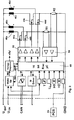
- Figure 2 is a block diagram of an electronic control circuit; and
- Figure 3 is a diagram of belt forces vs. withdrawn webbing length.
- The seat belt retractor in Figure 1 has a
frame 10 with two opposedwalls belt spool 12 is rotatably mounted.Wall 10b offrame 10 has anextension 10c whereon anelectric drive motor 14 is mounted. Theelectric motor 14 has astator 16 carried by abearing sleeve 18 that has an axial end fixed in an opening ofwall extension 10c. Theelectric motor 14 has anexternal rotor 20 connected to ashaft 22 rotatably mounted in and axially extending throughbearing sleeve 18.Shaft 22 has an output end projecting from thebearing sleeve 18 with apinion 24 attached thereto for joint rotation. An externallytoothed wheel 26 is attached to one axial end ofbelt spool 12 for joint rotation. Atoothed belt 28 is trained aboutpinion 24 andwheel 26.Wheel 26 has an outer diameter much greater than that ofpinion 24, thereby forming a reduction belt gear coupling theelectric motor 14 tobelt spool 12. -
Wheel 26 has an annular cavity to form a spring cage for accommodation of a helical windingspring 30. Windingspring 30 has an outer end connected towheel 26 and an inner end connected to acylindrical bushing 32 fixed in an opening ofwall 10b offrame 10.Bushing 32 includes a bearing forrotatably mounting spool 12 onframe 10. - On its axial side opposite
wheel 26,belt spool 12 has an axial end rigidly connected to alocking wheel 34 for co-operation with alocking pawl 36 controlled by asolenoid 38. - An electric control unit is mounted on a printed
circuit board 40 and includes a number of electronic components such as acapacitor 42,power FET transistors 44 and an integrated circuit incorporating a microprocessor. The printedcircuit board 40 extends parallel towall extension 10c and is slightly spaced therefrom. - An
elongate cover 50 is fitted overwheel 26,belt 28,pinion 24 and partially over the components of the electronic control circuit and is attached toframe 10. Ahood 52 is fitted over theelectric motor 14 and also attached toframe 10 so as to form a continuous enclosure withcover 50 to accommodate the electric motor, the electronic control unit and the reduction belt gear. Anothercover 54 is fitted over the locking mechanism formed bylocking wheel 34,pawl 36 andsolenoid 38. - The electronic control unit shown in Figure 2 includes a
microprocessor 60 with a number of inputs and outputs. Outputs ofmicroprocessor 60 are connected to adriver circuit 62 the outputs of which are in turn connected to control gates ofpower FETs stator 16. Current sense resistors R1, R2 are connected in series with the windings ofstator 16. Each of the current sense resistors R1, R2 provides a voltage drop indicative of current flowing through the windings ofelectric motor 14 and applied to a pair of inputs ofmicroprocessor 60 through aninput driver 64. A pair of HALL detectors H1, H2 are connected to corresponding inputs ofmicroprocessor 60. HALL detectors H1, H2 are associated withrotor 20 ofelectric motor 14 to detect rotational positions ofrotor 20. By detecting rotational positions ofrotor 20,microprocessor 60, on the one hand, controls commutation ofelectric motor 14 and, on the other hand, counts incremental steps of rotation so as to keep track of the absolute angle of rotation ofbelt spool 12 and, therefore, of webbing length withdrawn frombelt spool 12. Another input ofmicroprocessor 60 is connected to apre-crash sensor 66 mounted in the vehicle where the seat belt retractor is installed. - Operation of the seat belt retractor will now be explained with reference to Figure 3. In Figure 3, line S shows the force permanently developed by winding
spring 30 and appearing as a belt tension force. The belt tension force is a function of belt length withdrawn frombelt spool 12. This force rises from an initial value of 5 N (fully retracted belt) to a value of above 10 N (more than 1,000 mm of belt length withdrawn). Any force developed byelectric motor 14 is either added to or subtracted from the force developed by windingspring 30, depending on the sign of torque transmitted frommotor 14 tobelt spool 12 via the reduction belt gear. The resulting belt tension force is that experienced by the occupant wearing the seat belt, and is also that responsible for winding belt webbing onbelt spool 12. - In the preferred embodiment, a first, relatively high level of belt tension is substantially constant over the length of belt webbing withdrawn from
belt spool 12, as indicated by line (1) in Fig. 3. The first level (1) is used for retracting the belt webbing onspool 12. It results from the combined forces of windingspring 30 andmotor 14, the force developed bymotor 14 being indicated by line M(1) in Fig. 3. Force M(1) is initially on the order of 2N (fully retracted belt webbing), decreases to 0 after withdrawl of a small length of belt webbing (about 300 mm in Fig. 3) and changes sign to reach negative values compensating for the increasing forces developed by windingspring 30. A second, relatively low level of belt tension is also substantially constant over the length of belt webbing withdrawn frombelt spool 12, as indicated by line (2) in Fig. 3. The second level (2) is used after the occupant has buckled the seat belt and is dimensioned for comfort. It also results from the combined forces of windingspring 30 andmotor 14, the force developed bymotor 14 being indicated by line M(2) in Fig. 3. Force M(2) is initially negative on the order of - 1N (fully retracted belt webbing) and steadily increases to higher negative values to compensate for the increasing forces developed by windingspring 30. Switching between the first and second levels (1) and (2) is controlled bymicroprocessor 60 as a function of the length of belt webbing withdrawn frombelt spool 12, as determined by the count of incremental rotation steps ofmotor 14, and comparing the current length of belt webbing with predetermined thresholds. - A third, much higher level of belt tension forces (not shown in Fig. 3) is used in a pre-crash situation as signalled by
pre-crash sensor 66. - In the event of an electric power failure, the winding
spring 30 still provides a winding force according to line S in Fig. 3, only somewhat reduced by frictional losses in the reduction belt gear. Windingspring 30 is dimensioned to provide a sufficient winding force under all circumstances to safely retract the belt webbing onbelt spool 12.
Claims (9)
- A seat belt retractor comprising a retractor frame, a belt spool rotatably mounted in the frame, an electric drive motor, a reduction belt gear with a toothed belt connecting the electric motor permanently with the belt spool, and a winding spring functionally arranged between said frame and said belt spool and permanently biasing the belt spool with a winding moment, the electric motor being controlled to either counteract or assist the winding spring.
- The seat belt retractor of claim 1, wherein said winding spring is dimensioned to drive said belt spool and simultaneously entrain said electric motor through said belt gear when said electric motor is inoperative.
- The seat belt retractor of claim 1 or claim 2, wherein a length of belt webbing withdrawn from the belt spool is detected, the length of belt webbing withdrawn is compared to predetermined threshold values to discriminate between a belt wearing condition and a belt non-wearing condition, and the electric motor is driven in the wearing condition with current of a first polarity and adjusted to counteract the winding spring for appropriate belt wearing comfort, and is driven in a non-wearing condition with current of a second, opposite polarity adjusted for full retraction of belt webbing on the belt spool.
- The seat belt retractor of any of claims 1 to 3, wherein the electric motor is driven by an electronic control unit that has an input for a pre-crash sensor, and the electronic control unit drives said electric motor with a maximum winding moment for seat belt pre-tensioning.
- The seat belt retractor of any of claims 1 to 4, wherein said belt gear includes a gear wheel connected to the belt spool for joint rotation, said gear wheel forming a spring cage, and said winding spring is a helical spring accommodated in said spring cage.
- The seat belt retractor of claim 5, wherein said helical spring has a first, outer end connected to said gear wheel and a second, inner end connected to a bearing sleeve fixed to the retractor frame and rotatably mounting the gear wheel and the belt spool rigidly connected thereto on a first axial end of the belt spool.
- The seat belt retractor of claim 6, and comprising a locking mechanism for selectively locking the belt spool on the retractor frame, the locking mechanism being arranged on a second axial end of the belt spool.
- The seat belt retractor of claim 3, wherein a belt tension force resulting from combined forces of the winding spring and of the electric motor is substantially constant on a first, relatively low level over a range of belt webbing length withdrawn from the belt spool that corresponds to a belt-wearing condition.
- The seat belt retractor of claim 3, wherein a belt tension force resulting from combined forces of the winding spring and of the electric motor is substantially constant on a second, relatively high level over a range of belt webbing length withdrawn from the belt spool that corresponds to a belt-retraction condition.
Applications Claiming Priority (2)
| Application Number | Priority Date | Filing Date | Title |
|---|---|---|---|
| DE10111323A DE10111323A1 (en) | 2001-03-08 | 2001-03-08 | Reversible belt tensioner |
| DE10111323 | 2001-03-08 |
Publications (3)
| Publication Number | Publication Date |
|---|---|
| EP1238873A2 true EP1238873A2 (en) | 2002-09-11 |
| EP1238873A3 EP1238873A3 (en) | 2004-09-29 |
| EP1238873B1 EP1238873B1 (en) | 2005-12-28 |
Family
ID=7676834
Family Applications (1)
| Application Number | Title | Priority Date | Filing Date |
|---|---|---|---|
| EP02004206A Expired - Lifetime EP1238873B1 (en) | 2001-03-08 | 2002-02-25 | Seat belt retractor |
Country Status (5)
| Country | Link |
|---|---|
| US (1) | US6676056B2 (en) |
| EP (1) | EP1238873B1 (en) |
| JP (1) | JP3813518B2 (en) |
| DE (2) | DE10111323A1 (en) |
| ES (1) | ES2256346T3 (en) |
Cited By (7)
| Publication number | Priority date | Publication date | Assignee | Title |
|---|---|---|---|---|
| EP1738979A1 (en) * | 2005-06-30 | 2007-01-03 | Takata Corporation | Seat belt retractor and seat belt device having the same |
| WO2008049562A1 (en) * | 2006-10-24 | 2008-05-02 | Autoliv Development Ab | Seat belt retractor |
| DE102009010093A1 (en) * | 2009-02-24 | 2010-11-04 | Autoliv Development Ab | Reversible belt tensioner |
| DE102004054078B4 (en) * | 2004-11-09 | 2013-03-07 | Key Safety Systems, Inc. | Method for blocking a winding shaft of a seat belt retractor |
| CN103221269A (en) * | 2010-11-17 | 2013-07-24 | Trw汽车股份有限公司 | Seatbelt retractor for a seatbelt system and method for installing a seatbelt retractor |
| DE102008042892B4 (en) * | 2008-10-16 | 2020-12-10 | Brose Fahrzeugteile SE & Co. Kommanditgesellschaft, Würzburg | Belt tensioner drive and passenger restraint system |
| DE102019214892A1 (en) * | 2019-09-27 | 2021-04-01 | Joyson Safety Systems Germany Gmbh | Belt retractor |
Families Citing this family (21)
| Publication number | Priority date | Publication date | Assignee | Title |
|---|---|---|---|---|
| US6935590B2 (en) * | 2003-05-19 | 2005-08-30 | Autoliv Asp, Inc. | Sensor for a feedback control system |
| DE102004022134A1 (en) * | 2004-05-05 | 2005-12-01 | Trw Automotive Gmbh | Belt retractor for a vehicle seat belt |
| JP4458526B2 (en) * | 2004-07-21 | 2010-04-28 | タカタ株式会社 | Seat belt retractor and seat belt device |
| JP4714525B2 (en) * | 2005-08-05 | 2011-06-29 | タカタ株式会社 | Seat belt retractor, seat belt device, vehicle with seat belt device |
| JP4726727B2 (en) * | 2006-07-18 | 2011-07-20 | 本田技研工業株式会社 | Vehicle seat belt device |
| US8093731B2 (en) * | 2006-11-07 | 2012-01-10 | Potenco, Inc. | Gearless human power generation |
| US7747355B2 (en) * | 2006-11-07 | 2010-06-29 | Potenco, Inc. | Electrical power generator with adaptive coupling |
| US20080157536A1 (en) * | 2006-11-07 | 2008-07-03 | Potenco, Inc. | Anchor for a human power generator |
| JP4889579B2 (en) * | 2007-06-26 | 2012-03-07 | 本田技研工業株式会社 | Vehicle seat belt device |
| JP5038864B2 (en) * | 2007-11-20 | 2012-10-03 | 日立オートモティブシステムズ株式会社 | Seat belt retractor control device and seat belt retractor |
| JP5160355B2 (en) * | 2008-09-16 | 2013-03-13 | タカタ株式会社 | Seat belt retractor and seat belt device provided with the same |
| JP5261736B2 (en) * | 2008-09-16 | 2013-08-14 | タカタ株式会社 | Seat belt retractor and seat belt device provided with the same |
| EP2743142B1 (en) * | 2012-12-12 | 2020-03-25 | Volvo Car Corporation | Method for retracting a seat belt |
| DE102013203144B4 (en) * | 2013-02-26 | 2022-04-14 | Autoliv Development Ab | Belt retractor with an electromotive winding aid and method for controlling an electromotive winding aid for a belt retractor |
| DE102013014702A1 (en) * | 2013-09-05 | 2015-03-05 | GM Global Technology Operations LLC (n. d. Ges. d. Staates Delaware) | safety belt assembly |
| DE102014008547A1 (en) * | 2014-06-16 | 2015-12-17 | Trw Automotive Safety Systems Gmbh | Method for controlling the engine speed of an electric retractor motor of a belt retractor |
| CN111212767B (en) * | 2017-08-07 | 2022-12-09 | 关键安全体系股份有限公司 | Integrated electric motor retractor with motion profile (IMR) |
| DE102019206439B4 (en) * | 2019-05-06 | 2021-11-11 | Autoliv Development Ab | Belt retractor |
| US12017605B2 (en) * | 2022-09-15 | 2024-06-25 | Ford Global Technologies, Llc | Slidable seatbelt assembly for a wheelchair |
| EP4501715B1 (en) * | 2023-08-02 | 2026-01-21 | Autoliv Development AB | Retractor for a seatbelt device |
| EP4501716B1 (en) * | 2023-08-02 | 2026-01-28 | Autoliv Development AB | Retractor for a seatbelt device |
Family Cites Families (16)
| Publication number | Priority date | Publication date | Assignee | Title |
|---|---|---|---|---|
| DE2511442C3 (en) * | 1975-03-15 | 1978-11-02 | Robert Bosch Gmbh, 7000 Stuttgart | Seat belt device |
| US4478433A (en) * | 1981-11-04 | 1984-10-23 | Nippon Soken, Inc. | Safety seatbelt retractor |
| DE3149573A1 (en) * | 1981-12-15 | 1983-06-30 | Volkswagenwerk Ag, 3180 Wolfsburg | Safety-belt winding device |
| JPS602218B2 (en) * | 1982-02-16 | 1985-01-19 | 株式会社 高田工場 | safety belt retractor |
| JPS58185351A (en) * | 1982-04-26 | 1983-10-29 | Nissan Motor Co Ltd | Seat belt retractor |
| JPS6087754U (en) * | 1983-11-11 | 1985-06-17 | 株式会社東海理化電機製作所 | webbing retractor |
| JPH08522B2 (en) * | 1985-05-22 | 1996-01-10 | 日産自動車株式会社 | Seat belt retractor |
| JPH0452131Y2 (en) * | 1985-10-22 | 1992-12-08 | ||
| US4907757A (en) * | 1989-06-14 | 1990-03-13 | Trw Vehicle Safety Systems Inc. | Comfort mechanism with slack limit |
| US5244231A (en) * | 1990-11-27 | 1993-09-14 | Trw Vehicle Safety Systems Inc. | Seat belt system with comfort control |
| US5558370A (en) * | 1995-03-30 | 1996-09-24 | Automotive Systems Laboratory, Inc. | Electronic seat belt tensioning system |
| DE19731689C2 (en) * | 1997-07-23 | 1999-07-29 | Hs Tech & Design | Device for rolling up a seat belt |
| JP4467688B2 (en) * | 1999-01-19 | 2010-05-26 | タカタ株式会社 | Seat belt retractor |
| DE19957814C2 (en) * | 1999-12-01 | 2003-07-31 | Trw Automotive Electron & Comp | Gurtaufrollersystem |
| DE10013870B4 (en) * | 2000-03-21 | 2007-04-05 | Key Safety Systems, Inc., Sterling Heights | Belt retractor for a vehicle seat belt |
| DE10013869C2 (en) * | 2000-03-21 | 2002-06-20 | Breed Automotive Tech | Comfort take-up device for a seat belt with motor return |
-
2001
- 2001-03-08 DE DE10111323A patent/DE10111323A1/en not_active Ceased
-
2002
- 2002-02-25 EP EP02004206A patent/EP1238873B1/en not_active Expired - Lifetime
- 2002-02-25 DE DE60208253T patent/DE60208253T2/en not_active Expired - Lifetime
- 2002-02-25 ES ES02004206T patent/ES2256346T3/en not_active Expired - Lifetime
- 2002-02-27 US US10/085,271 patent/US6676056B2/en not_active Expired - Fee Related
- 2002-03-08 JP JP2002063288A patent/JP3813518B2/en not_active Expired - Fee Related
Non-Patent Citations (1)
| Title |
|---|
| None |
Cited By (8)
| Publication number | Priority date | Publication date | Assignee | Title |
|---|---|---|---|---|
| DE102004054078B4 (en) * | 2004-11-09 | 2013-03-07 | Key Safety Systems, Inc. | Method for blocking a winding shaft of a seat belt retractor |
| EP1738979A1 (en) * | 2005-06-30 | 2007-01-03 | Takata Corporation | Seat belt retractor and seat belt device having the same |
| WO2008049562A1 (en) * | 2006-10-24 | 2008-05-02 | Autoliv Development Ab | Seat belt retractor |
| DE102008042892B4 (en) * | 2008-10-16 | 2020-12-10 | Brose Fahrzeugteile SE & Co. Kommanditgesellschaft, Würzburg | Belt tensioner drive and passenger restraint system |
| DE102009010093A1 (en) * | 2009-02-24 | 2010-11-04 | Autoliv Development Ab | Reversible belt tensioner |
| CN103221269A (en) * | 2010-11-17 | 2013-07-24 | Trw汽车股份有限公司 | Seatbelt retractor for a seatbelt system and method for installing a seatbelt retractor |
| CN103221269B (en) * | 2010-11-17 | 2017-03-01 | Trw汽车股份有限公司 | Safety-belt expansion device for restraint system and the method for assembling safety-belt expansion device |
| DE102019214892A1 (en) * | 2019-09-27 | 2021-04-01 | Joyson Safety Systems Germany Gmbh | Belt retractor |
Also Published As
| Publication number | Publication date |
|---|---|
| US6676056B2 (en) | 2004-01-13 |
| JP2002321597A (en) | 2002-11-05 |
| US20020125360A1 (en) | 2002-09-12 |
| DE60208253D1 (en) | 2006-02-02 |
| ES2256346T3 (en) | 2006-07-16 |
| EP1238873B1 (en) | 2005-12-28 |
| DE10111323A1 (en) | 2002-09-12 |
| EP1238873A3 (en) | 2004-09-29 |
| DE60208253T2 (en) | 2006-08-17 |
| JP3813518B2 (en) | 2006-08-23 |
Similar Documents
| Publication | Publication Date | Title |
|---|---|---|
| EP1238873B1 (en) | Seat belt retractor | |
| CN1140431C (en) | Seat belt retractors for occupant restraint systems | |
| DE19927731C2 (en) | pretensioners | |
| EP1524159B1 (en) | Seat belt retractor | |
| US8075019B2 (en) | Device for restraining a vehicle occupant | |
| KR20070073892A (en) | Seat belt retractor | |
| CN102712292B (en) | Seatbelt retractor and seatbelt device provided with same | |
| JP2008504160A (en) | Seat belt retractor with electric motor | |
| US6691944B2 (en) | Seat belt retractor | |
| US8893998B2 (en) | Belt retractor for a seat belt system | |
| US7416149B2 (en) | Webbing take-up device | |
| US6595453B2 (en) | Method of controlling the torque developed at a belt shaft of a belt retractor coupled to an electric motor | |
| EP1293401B1 (en) | Seatbelt retractor | |
| US20050284976A1 (en) | Method for operating a belt retractor and a belt retractor for a safety belt | |
| JP2004518570A (en) | Safety belt winder with belt tensioning device | |
| JP2011183873A (en) | Webbing winding device | |
| EP1625055A1 (en) | Electric seat belt retractor system | |
| KR100534864B1 (en) | Automatically safety seatbelt for vehicle | |
| JP5557696B2 (en) | Seat belt device | |
| JP2011037299A (en) | Webbing winding device |
Legal Events
| Date | Code | Title | Description |
|---|---|---|---|
| PUAI | Public reference made under article 153(3) epc to a published international application that has entered the european phase |
Free format text: ORIGINAL CODE: 0009012 |
|
| AK | Designated contracting states |
Kind code of ref document: A2 Designated state(s): AT BE CH CY DE DK ES FI FR GB GR IE IT LI LU MC NL PT SE TR |
|
| AX | Request for extension of the european patent |
Free format text: AL;LT;LV;MK;RO;SI |
|
| PUAL | Search report despatched |
Free format text: ORIGINAL CODE: 0009013 |
|
| AK | Designated contracting states |
Kind code of ref document: A3 Designated state(s): AT BE CH CY DE DK ES FI FR GB GR IE IT LI LU MC NL PT SE TR |
|
| AX | Request for extension of the european patent |
Extension state: AL LT LV MK RO SI |
|
| GRAP | Despatch of communication of intention to grant a patent |
Free format text: ORIGINAL CODE: EPIDOSNIGR1 |
|
| 17P | Request for examination filed |
Effective date: 20041222 |
|
| AKX | Designation fees paid |
Designated state(s): DE ES FR GB IT PT |
|
| GRAS | Grant fee paid |
Free format text: ORIGINAL CODE: EPIDOSNIGR3 |
|
| GRAA | (expected) grant |
Free format text: ORIGINAL CODE: 0009210 |
|
| AK | Designated contracting states |
Kind code of ref document: B1 Designated state(s): DE ES FR GB IT PT |
|
| REG | Reference to a national code |
Ref country code: GB Ref legal event code: FG4D |
|
| REF | Corresponds to: |
Ref document number: 60208253 Country of ref document: DE Date of ref document: 20060202 Kind code of ref document: P |
|
| REG | Reference to a national code |
Ref country code: ES Ref legal event code: FG2A Ref document number: 2256346 Country of ref document: ES Kind code of ref document: T3 |
|
| ET | Fr: translation filed | ||
| PLBE | No opposition filed within time limit |
Free format text: ORIGINAL CODE: 0009261 |
|
| STAA | Information on the status of an ep patent application or granted ep patent |
Free format text: STATUS: NO OPPOSITION FILED WITHIN TIME LIMIT |
|
| 26N | No opposition filed |
Effective date: 20060929 |
|
| PGFP | Annual fee paid to national office [announced via postgrant information from national office to epo] |
Ref country code: PT Payment date: 20080103 Year of fee payment: 7 |
|
| PGFP | Annual fee paid to national office [announced via postgrant information from national office to epo] |
Ref country code: ES Payment date: 20090218 Year of fee payment: 8 |
|
| PGFP | Annual fee paid to national office [announced via postgrant information from national office to epo] |
Ref country code: GB Payment date: 20090106 Year of fee payment: 8 |
|
| PGFP | Annual fee paid to national office [announced via postgrant information from national office to epo] |
Ref country code: IT Payment date: 20090214 Year of fee payment: 8 |
|
| REG | Reference to a national code |
Ref country code: PT Ref legal event code: MM4A Free format text: LAPSE DUE TO NON-PAYMENT OF FEES Effective date: 20090825 |
|
| PG25 | Lapsed in a contracting state [announced via postgrant information from national office to epo] |
Ref country code: PT Free format text: LAPSE BECAUSE OF NON-PAYMENT OF DUE FEES Effective date: 20090825 |
|
| PGFP | Annual fee paid to national office [announced via postgrant information from national office to epo] |
Ref country code: FR Payment date: 20090206 Year of fee payment: 8 |
|
| GBPC | Gb: european patent ceased through non-payment of renewal fee |
Effective date: 20100225 |
|
| REG | Reference to a national code |
Ref country code: FR Ref legal event code: ST Effective date: 20101029 |
|
| PG25 | Lapsed in a contracting state [announced via postgrant information from national office to epo] |
Ref country code: FR Free format text: LAPSE BECAUSE OF NON-PAYMENT OF DUE FEES Effective date: 20100301 |
|
| REG | Reference to a national code |
Ref country code: ES Ref legal event code: FD2A Effective date: 20110308 |
|
| PG25 | Lapsed in a contracting state [announced via postgrant information from national office to epo] |
Ref country code: GB Free format text: LAPSE BECAUSE OF NON-PAYMENT OF DUE FEES Effective date: 20100225 Ref country code: IT Free format text: LAPSE BECAUSE OF NON-PAYMENT OF DUE FEES Effective date: 20100225 |
|
| PG25 | Lapsed in a contracting state [announced via postgrant information from national office to epo] |
Ref country code: ES Free format text: LAPSE BECAUSE OF NON-PAYMENT OF DUE FEES Effective date: 20110307 |
|
| PG25 | Lapsed in a contracting state [announced via postgrant information from national office to epo] |
Ref country code: ES Free format text: LAPSE BECAUSE OF NON-PAYMENT OF DUE FEES Effective date: 20100226 |
|
| REG | Reference to a national code |
Ref country code: DE Ref legal event code: R081 Ref document number: 60208253 Country of ref document: DE Owner name: TRW AUTOMOTIVE GMBH, DE Free format text: FORMER OWNER: TRW AUTOMOTIVE ELECTRONICS & COMPONENTS GMBH & CO. KG, 78315 RADOLFZELL, DE Ref country code: DE Ref legal event code: R082 Ref document number: 60208253 Country of ref document: DE Representative=s name: PRINZ & PARTNER MBB PATENTANWAELTE RECHTSANWAE, DE |
|
| PGFP | Annual fee paid to national office [announced via postgrant information from national office to epo] |
Ref country code: DE Payment date: 20210225 Year of fee payment: 20 |
|
| REG | Reference to a national code |
Ref country code: DE Ref legal event code: R071 Ref document number: 60208253 Country of ref document: DE |