EP1238839A1 - Transparent plate with molding, and method of removing transparent plate - Google Patents
Transparent plate with molding, and method of removing transparent plate Download PDFInfo
- Publication number
- EP1238839A1 EP1238839A1 EP00981688A EP00981688A EP1238839A1 EP 1238839 A1 EP1238839 A1 EP 1238839A1 EP 00981688 A EP00981688 A EP 00981688A EP 00981688 A EP00981688 A EP 00981688A EP 1238839 A1 EP1238839 A1 EP 1238839A1
- Authority
- EP
- European Patent Office
- Prior art keywords
- molding
- transparent plate
- electrically conductive
- conductive member
- glass plate
- Prior art date
- Legal status (The legal status is an assumption and is not a legal conclusion. Google has not performed a legal analysis and makes no representation as to the accuracy of the status listed.)
- Withdrawn
Links
Images





Classifications
-
- B—PERFORMING OPERATIONS; TRANSPORTING
- B60—VEHICLES IN GENERAL
- B60J—WINDOWS, WINDSCREENS, NON-FIXED ROOFS, DOORS, OR SIMILAR DEVICES FOR VEHICLES; REMOVABLE EXTERNAL PROTECTIVE COVERINGS SPECIALLY ADAPTED FOR VEHICLES
- B60J1/00—Windows; Windscreens; Accessories therefor
- B60J1/02—Windows; Windscreens; Accessories therefor arranged at the vehicle front, e.g. structure of the glazing, mounting of the glazing
-
- B—PERFORMING OPERATIONS; TRANSPORTING
- B29—WORKING OF PLASTICS; WORKING OF SUBSTANCES IN A PLASTIC STATE IN GENERAL
- B29C—SHAPING OR JOINING OF PLASTICS; SHAPING OF MATERIAL IN A PLASTIC STATE, NOT OTHERWISE PROVIDED FOR; AFTER-TREATMENT OF THE SHAPED PRODUCTS, e.g. REPAIRING
- B29C48/00—Extrusion moulding, i.e. expressing the moulding material through a die or nozzle which imparts the desired form; Apparatus therefor
- B29C48/15—Extrusion moulding, i.e. expressing the moulding material through a die or nozzle which imparts the desired form; Apparatus therefor incorporating preformed parts or layers, e.g. extrusion moulding around inserts
- B29C48/154—Coating solid articles, i.e. non-hollow articles
- B29C48/155—Partial coating thereof
-
- B—PERFORMING OPERATIONS; TRANSPORTING
- B29—WORKING OF PLASTICS; WORKING OF SUBSTANCES IN A PLASTIC STATE IN GENERAL
- B29C—SHAPING OR JOINING OF PLASTICS; SHAPING OF MATERIAL IN A PLASTIC STATE, NOT OTHERWISE PROVIDED FOR; AFTER-TREATMENT OF THE SHAPED PRODUCTS, e.g. REPAIRING
- B29C65/00—Joining or sealing of preformed parts, e.g. welding of plastics materials; Apparatus therefor
- B29C65/02—Joining or sealing of preformed parts, e.g. welding of plastics materials; Apparatus therefor by heating, with or without pressure
- B29C65/34—Joining or sealing of preformed parts, e.g. welding of plastics materials; Apparatus therefor by heating, with or without pressure using heated elements which remain in the joint, e.g. "verlorenes Schweisselement"
-
- B—PERFORMING OPERATIONS; TRANSPORTING
- B29—WORKING OF PLASTICS; WORKING OF SUBSTANCES IN A PLASTIC STATE IN GENERAL
- B29C—SHAPING OR JOINING OF PLASTICS; SHAPING OF MATERIAL IN A PLASTIC STATE, NOT OTHERWISE PROVIDED FOR; AFTER-TREATMENT OF THE SHAPED PRODUCTS, e.g. REPAIRING
- B29C65/00—Joining or sealing of preformed parts, e.g. welding of plastics materials; Apparatus therefor
- B29C65/02—Joining or sealing of preformed parts, e.g. welding of plastics materials; Apparatus therefor by heating, with or without pressure
- B29C65/34—Joining or sealing of preformed parts, e.g. welding of plastics materials; Apparatus therefor by heating, with or without pressure using heated elements which remain in the joint, e.g. "verlorenes Schweisselement"
- B29C65/36—Joining or sealing of preformed parts, e.g. welding of plastics materials; Apparatus therefor by heating, with or without pressure using heated elements which remain in the joint, e.g. "verlorenes Schweisselement" heated by induction
- B29C65/3604—Joining or sealing of preformed parts, e.g. welding of plastics materials; Apparatus therefor by heating, with or without pressure using heated elements which remain in the joint, e.g. "verlorenes Schweisselement" heated by induction characterised by the type of elements heated by induction which remain in the joint
- B29C65/3608—Joining or sealing of preformed parts, e.g. welding of plastics materials; Apparatus therefor by heating, with or without pressure using heated elements which remain in the joint, e.g. "verlorenes Schweisselement" heated by induction characterised by the type of elements heated by induction which remain in the joint comprising single particles, e.g. fillers or discontinuous fibre-reinforcements
- B29C65/3612—Joining or sealing of preformed parts, e.g. welding of plastics materials; Apparatus therefor by heating, with or without pressure using heated elements which remain in the joint, e.g. "verlorenes Schweisselement" heated by induction characterised by the type of elements heated by induction which remain in the joint comprising single particles, e.g. fillers or discontinuous fibre-reinforcements comprising fillers
-
- B—PERFORMING OPERATIONS; TRANSPORTING
- B29—WORKING OF PLASTICS; WORKING OF SUBSTANCES IN A PLASTIC STATE IN GENERAL
- B29C—SHAPING OR JOINING OF PLASTICS; SHAPING OF MATERIAL IN A PLASTIC STATE, NOT OTHERWISE PROVIDED FOR; AFTER-TREATMENT OF THE SHAPED PRODUCTS, e.g. REPAIRING
- B29C65/00—Joining or sealing of preformed parts, e.g. welding of plastics materials; Apparatus therefor
- B29C65/02—Joining or sealing of preformed parts, e.g. welding of plastics materials; Apparatus therefor by heating, with or without pressure
- B29C65/34—Joining or sealing of preformed parts, e.g. welding of plastics materials; Apparatus therefor by heating, with or without pressure using heated elements which remain in the joint, e.g. "verlorenes Schweisselement"
- B29C65/36—Joining or sealing of preformed parts, e.g. welding of plastics materials; Apparatus therefor by heating, with or without pressure using heated elements which remain in the joint, e.g. "verlorenes Schweisselement" heated by induction
- B29C65/3604—Joining or sealing of preformed parts, e.g. welding of plastics materials; Apparatus therefor by heating, with or without pressure using heated elements which remain in the joint, e.g. "verlorenes Schweisselement" heated by induction characterised by the type of elements heated by induction which remain in the joint
- B29C65/364—Joining or sealing of preformed parts, e.g. welding of plastics materials; Apparatus therefor by heating, with or without pressure using heated elements which remain in the joint, e.g. "verlorenes Schweisselement" heated by induction characterised by the type of elements heated by induction which remain in the joint being a woven or non-woven fabric or being a mesh
-
- B—PERFORMING OPERATIONS; TRANSPORTING
- B29—WORKING OF PLASTICS; WORKING OF SUBSTANCES IN A PLASTIC STATE IN GENERAL
- B29C—SHAPING OR JOINING OF PLASTICS; SHAPING OF MATERIAL IN A PLASTIC STATE, NOT OTHERWISE PROVIDED FOR; AFTER-TREATMENT OF THE SHAPED PRODUCTS, e.g. REPAIRING
- B29C65/00—Joining or sealing of preformed parts, e.g. welding of plastics materials; Apparatus therefor
- B29C65/02—Joining or sealing of preformed parts, e.g. welding of plastics materials; Apparatus therefor by heating, with or without pressure
- B29C65/34—Joining or sealing of preformed parts, e.g. welding of plastics materials; Apparatus therefor by heating, with or without pressure using heated elements which remain in the joint, e.g. "verlorenes Schweisselement"
- B29C65/36—Joining or sealing of preformed parts, e.g. welding of plastics materials; Apparatus therefor by heating, with or without pressure using heated elements which remain in the joint, e.g. "verlorenes Schweisselement" heated by induction
- B29C65/3604—Joining or sealing of preformed parts, e.g. welding of plastics materials; Apparatus therefor by heating, with or without pressure using heated elements which remain in the joint, e.g. "verlorenes Schweisselement" heated by induction characterised by the type of elements heated by induction which remain in the joint
- B29C65/3644—Joining or sealing of preformed parts, e.g. welding of plastics materials; Apparatus therefor by heating, with or without pressure using heated elements which remain in the joint, e.g. "verlorenes Schweisselement" heated by induction characterised by the type of elements heated by induction which remain in the joint being a ribbon, band or strip
-
- B—PERFORMING OPERATIONS; TRANSPORTING
- B29—WORKING OF PLASTICS; WORKING OF SUBSTANCES IN A PLASTIC STATE IN GENERAL
- B29C—SHAPING OR JOINING OF PLASTICS; SHAPING OF MATERIAL IN A PLASTIC STATE, NOT OTHERWISE PROVIDED FOR; AFTER-TREATMENT OF THE SHAPED PRODUCTS, e.g. REPAIRING
- B29C65/00—Joining or sealing of preformed parts, e.g. welding of plastics materials; Apparatus therefor
- B29C65/76—Making non-permanent or releasable joints
-
- B—PERFORMING OPERATIONS; TRANSPORTING
- B29—WORKING OF PLASTICS; WORKING OF SUBSTANCES IN A PLASTIC STATE IN GENERAL
- B29C—SHAPING OR JOINING OF PLASTICS; SHAPING OF MATERIAL IN A PLASTIC STATE, NOT OTHERWISE PROVIDED FOR; AFTER-TREATMENT OF THE SHAPED PRODUCTS, e.g. REPAIRING
- B29C66/00—General aspects of processes or apparatus for joining preformed parts
- B29C66/01—General aspects dealing with the joint area or with the area to be joined
- B29C66/05—Particular design of joint configurations
- B29C66/10—Particular design of joint configurations particular design of the joint cross-sections
- B29C66/11—Joint cross-sections comprising a single joint-segment, i.e. one of the parts to be joined comprising a single joint-segment in the joint cross-section
- B29C66/112—Single lapped joints
- B29C66/1122—Single lap to lap joints, i.e. overlap joints
-
- B—PERFORMING OPERATIONS; TRANSPORTING
- B29—WORKING OF PLASTICS; WORKING OF SUBSTANCES IN A PLASTIC STATE IN GENERAL
- B29C—SHAPING OR JOINING OF PLASTICS; SHAPING OF MATERIAL IN A PLASTIC STATE, NOT OTHERWISE PROVIDED FOR; AFTER-TREATMENT OF THE SHAPED PRODUCTS, e.g. REPAIRING
- B29C66/00—General aspects of processes or apparatus for joining preformed parts
- B29C66/01—General aspects dealing with the joint area or with the area to be joined
- B29C66/05—Particular design of joint configurations
- B29C66/10—Particular design of joint configurations particular design of the joint cross-sections
- B29C66/12—Joint cross-sections combining only two joint-segments; Tongue and groove joints; Tenon and mortise joints; Stepped joint cross-sections
- B29C66/122—Joint cross-sections combining only two joint-segments, i.e. one of the parts to be joined comprising only two joint-segments in the joint cross-section
- B29C66/1222—Joint cross-sections combining only two joint-segments, i.e. one of the parts to be joined comprising only two joint-segments in the joint cross-section comprising at least a lapped joint-segment
-
- B—PERFORMING OPERATIONS; TRANSPORTING
- B29—WORKING OF PLASTICS; WORKING OF SUBSTANCES IN A PLASTIC STATE IN GENERAL
- B29C—SHAPING OR JOINING OF PLASTICS; SHAPING OF MATERIAL IN A PLASTIC STATE, NOT OTHERWISE PROVIDED FOR; AFTER-TREATMENT OF THE SHAPED PRODUCTS, e.g. REPAIRING
- B29C66/00—General aspects of processes or apparatus for joining preformed parts
- B29C66/01—General aspects dealing with the joint area or with the area to be joined
- B29C66/05—Particular design of joint configurations
- B29C66/10—Particular design of joint configurations particular design of the joint cross-sections
- B29C66/12—Joint cross-sections combining only two joint-segments; Tongue and groove joints; Tenon and mortise joints; Stepped joint cross-sections
- B29C66/122—Joint cross-sections combining only two joint-segments, i.e. one of the parts to be joined comprising only two joint-segments in the joint cross-section
- B29C66/1224—Joint cross-sections combining only two joint-segments, i.e. one of the parts to be joined comprising only two joint-segments in the joint cross-section comprising at least a butt joint-segment
-
- B—PERFORMING OPERATIONS; TRANSPORTING
- B29—WORKING OF PLASTICS; WORKING OF SUBSTANCES IN A PLASTIC STATE IN GENERAL
- B29C—SHAPING OR JOINING OF PLASTICS; SHAPING OF MATERIAL IN A PLASTIC STATE, NOT OTHERWISE PROVIDED FOR; AFTER-TREATMENT OF THE SHAPED PRODUCTS, e.g. REPAIRING
- B29C66/00—General aspects of processes or apparatus for joining preformed parts
- B29C66/50—General aspects of joining tubular articles; General aspects of joining long products, i.e. bars or profiled elements; General aspects of joining single elements to tubular articles, hollow articles or bars; General aspects of joining several hollow-preforms to form hollow or tubular articles
- B29C66/51—Joining tubular articles, profiled elements or bars; Joining single elements to tubular articles, hollow articles or bars; Joining several hollow-preforms to form hollow or tubular articles
- B29C66/53—Joining single elements to tubular articles, hollow articles or bars
- B29C66/534—Joining single elements to open ends of tubular or hollow articles or to the ends of bars
- B29C66/5346—Joining single elements to open ends of tubular or hollow articles or to the ends of bars said single elements being substantially flat
-
- B—PERFORMING OPERATIONS; TRANSPORTING
- B29—WORKING OF PLASTICS; WORKING OF SUBSTANCES IN A PLASTIC STATE IN GENERAL
- B29C—SHAPING OR JOINING OF PLASTICS; SHAPING OF MATERIAL IN A PLASTIC STATE, NOT OTHERWISE PROVIDED FOR; AFTER-TREATMENT OF THE SHAPED PRODUCTS, e.g. REPAIRING
- B29C66/00—General aspects of processes or apparatus for joining preformed parts
- B29C66/50—General aspects of joining tubular articles; General aspects of joining long products, i.e. bars or profiled elements; General aspects of joining single elements to tubular articles, hollow articles or bars; General aspects of joining several hollow-preforms to form hollow or tubular articles
- B29C66/65—General aspects of joining tubular articles; General aspects of joining long products, i.e. bars or profiled elements; General aspects of joining single elements to tubular articles, hollow articles or bars; General aspects of joining several hollow-preforms to form hollow or tubular articles with a relative motion between the article and the welding tool
-
- B—PERFORMING OPERATIONS; TRANSPORTING
- B29—WORKING OF PLASTICS; WORKING OF SUBSTANCES IN A PLASTIC STATE IN GENERAL
- B29C—SHAPING OR JOINING OF PLASTICS; SHAPING OF MATERIAL IN A PLASTIC STATE, NOT OTHERWISE PROVIDED FOR; AFTER-TREATMENT OF THE SHAPED PRODUCTS, e.g. REPAIRING
- B29C66/00—General aspects of processes or apparatus for joining preformed parts
- B29C66/80—General aspects of machine operations or constructions and parts thereof
- B29C66/83—General aspects of machine operations or constructions and parts thereof characterised by the movement of the joining or pressing tools
- B29C66/836—Moving relative to and tangentially to the parts to be joined, e.g. transversely to the displacement of the parts to be joined, e.g. using a X-Y table
-
- B—PERFORMING OPERATIONS; TRANSPORTING
- B29—WORKING OF PLASTICS; WORKING OF SUBSTANCES IN A PLASTIC STATE IN GENERAL
- B29C—SHAPING OR JOINING OF PLASTICS; SHAPING OF MATERIAL IN A PLASTIC STATE, NOT OTHERWISE PROVIDED FOR; AFTER-TREATMENT OF THE SHAPED PRODUCTS, e.g. REPAIRING
- B29C48/00—Extrusion moulding, i.e. expressing the moulding material through a die or nozzle which imparts the desired form; Apparatus therefor
- B29C48/03—Extrusion moulding, i.e. expressing the moulding material through a die or nozzle which imparts the desired form; Apparatus therefor characterised by the shape of the extruded material at extrusion
- B29C48/12—Articles with an irregular circumference when viewed in cross-section, e.g. window profiles
-
- B—PERFORMING OPERATIONS; TRANSPORTING
- B29—WORKING OF PLASTICS; WORKING OF SUBSTANCES IN A PLASTIC STATE IN GENERAL
- B29C—SHAPING OR JOINING OF PLASTICS; SHAPING OF MATERIAL IN A PLASTIC STATE, NOT OTHERWISE PROVIDED FOR; AFTER-TREATMENT OF THE SHAPED PRODUCTS, e.g. REPAIRING
- B29C65/00—Joining or sealing of preformed parts, e.g. welding of plastics materials; Apparatus therefor
- B29C65/02—Joining or sealing of preformed parts, e.g. welding of plastics materials; Apparatus therefor by heating, with or without pressure
- B29C65/34—Joining or sealing of preformed parts, e.g. welding of plastics materials; Apparatus therefor by heating, with or without pressure using heated elements which remain in the joint, e.g. "verlorenes Schweisselement"
- B29C65/3472—Joining or sealing of preformed parts, e.g. welding of plastics materials; Apparatus therefor by heating, with or without pressure using heated elements which remain in the joint, e.g. "verlorenes Schweisselement" characterised by the composition of the heated elements which remain in the joint
- B29C65/3476—Joining or sealing of preformed parts, e.g. welding of plastics materials; Apparatus therefor by heating, with or without pressure using heated elements which remain in the joint, e.g. "verlorenes Schweisselement" characterised by the composition of the heated elements which remain in the joint being metallic
-
- B—PERFORMING OPERATIONS; TRANSPORTING
- B29—WORKING OF PLASTICS; WORKING OF SUBSTANCES IN A PLASTIC STATE IN GENERAL
- B29C—SHAPING OR JOINING OF PLASTICS; SHAPING OF MATERIAL IN A PLASTIC STATE, NOT OTHERWISE PROVIDED FOR; AFTER-TREATMENT OF THE SHAPED PRODUCTS, e.g. REPAIRING
- B29C65/00—Joining or sealing of preformed parts, e.g. welding of plastics materials; Apparatus therefor
- B29C65/02—Joining or sealing of preformed parts, e.g. welding of plastics materials; Apparatus therefor by heating, with or without pressure
- B29C65/34—Joining or sealing of preformed parts, e.g. welding of plastics materials; Apparatus therefor by heating, with or without pressure using heated elements which remain in the joint, e.g. "verlorenes Schweisselement"
- B29C65/36—Joining or sealing of preformed parts, e.g. welding of plastics materials; Apparatus therefor by heating, with or without pressure using heated elements which remain in the joint, e.g. "verlorenes Schweisselement" heated by induction
- B29C65/3672—Joining or sealing of preformed parts, e.g. welding of plastics materials; Apparatus therefor by heating, with or without pressure using heated elements which remain in the joint, e.g. "verlorenes Schweisselement" heated by induction characterised by the composition of the elements heated by induction which remain in the joint
- B29C65/3676—Joining or sealing of preformed parts, e.g. welding of plastics materials; Apparatus therefor by heating, with or without pressure using heated elements which remain in the joint, e.g. "verlorenes Schweisselement" heated by induction characterised by the composition of the elements heated by induction which remain in the joint being metallic
-
- B—PERFORMING OPERATIONS; TRANSPORTING
- B29—WORKING OF PLASTICS; WORKING OF SUBSTANCES IN A PLASTIC STATE IN GENERAL
- B29C—SHAPING OR JOINING OF PLASTICS; SHAPING OF MATERIAL IN A PLASTIC STATE, NOT OTHERWISE PROVIDED FOR; AFTER-TREATMENT OF THE SHAPED PRODUCTS, e.g. REPAIRING
- B29C65/00—Joining or sealing of preformed parts, e.g. welding of plastics materials; Apparatus therefor
- B29C65/78—Means for handling the parts to be joined, e.g. for making containers or hollow articles, e.g. means for handling sheets, plates, web-like materials, tubular articles, hollow articles or elements to be joined therewith; Means for discharging the joined articles from the joining apparatus
- B29C65/7841—Holding or clamping means for handling purposes
- B29C65/7847—Holding or clamping means for handling purposes using vacuum to hold at least one of the parts to be joined
-
- B—PERFORMING OPERATIONS; TRANSPORTING
- B29—WORKING OF PLASTICS; WORKING OF SUBSTANCES IN A PLASTIC STATE IN GENERAL
- B29C—SHAPING OR JOINING OF PLASTICS; SHAPING OF MATERIAL IN A PLASTIC STATE, NOT OTHERWISE PROVIDED FOR; AFTER-TREATMENT OF THE SHAPED PRODUCTS, e.g. REPAIRING
- B29C66/00—General aspects of processes or apparatus for joining preformed parts
- B29C66/70—General aspects of processes or apparatus for joining preformed parts characterised by the composition, physical properties or the structure of the material of the parts to be joined; Joining with non-plastics material
- B29C66/71—General aspects of processes or apparatus for joining preformed parts characterised by the composition, physical properties or the structure of the material of the parts to be joined; Joining with non-plastics material characterised by the composition of the plastics material of the parts to be joined
-
- B—PERFORMING OPERATIONS; TRANSPORTING
- B29—WORKING OF PLASTICS; WORKING OF SUBSTANCES IN A PLASTIC STATE IN GENERAL
- B29C—SHAPING OR JOINING OF PLASTICS; SHAPING OF MATERIAL IN A PLASTIC STATE, NOT OTHERWISE PROVIDED FOR; AFTER-TREATMENT OF THE SHAPED PRODUCTS, e.g. REPAIRING
- B29C66/00—General aspects of processes or apparatus for joining preformed parts
- B29C66/80—General aspects of machine operations or constructions and parts thereof
-
- B—PERFORMING OPERATIONS; TRANSPORTING
- B29—WORKING OF PLASTICS; WORKING OF SUBSTANCES IN A PLASTIC STATE IN GENERAL
- B29K—INDEXING SCHEME ASSOCIATED WITH SUBCLASSES B29B, B29C OR B29D, RELATING TO MOULDING MATERIALS OR TO MATERIALS FOR MOULDS, REINFORCEMENTS, FILLERS OR PREFORMED PARTS, e.g. INSERTS
- B29K2709/00—Use of inorganic materials not provided for in groups B29K2703/00 - B29K2707/00, for preformed parts, e.g. for inserts
- B29K2709/08—Glass
-
- B—PERFORMING OPERATIONS; TRANSPORTING
- B29—WORKING OF PLASTICS; WORKING OF SUBSTANCES IN A PLASTIC STATE IN GENERAL
- B29L—INDEXING SCHEME ASSOCIATED WITH SUBCLASS B29C, RELATING TO PARTICULAR ARTICLES
- B29L2031/00—Other particular articles
- B29L2031/001—Profiled members, e.g. beams, sections
- B29L2031/003—Profiled members, e.g. beams, sections having a profiled transverse cross-section
-
- B—PERFORMING OPERATIONS; TRANSPORTING
- B29—WORKING OF PLASTICS; WORKING OF SUBSTANCES IN A PLASTIC STATE IN GENERAL
- B29L—INDEXING SCHEME ASSOCIATED WITH SUBCLASS B29C, RELATING TO PARTICULAR ARTICLES
- B29L2031/00—Other particular articles
- B29L2031/26—Sealing devices, e.g. packaging for pistons or pipe joints
-
- Y—GENERAL TAGGING OF NEW TECHNOLOGICAL DEVELOPMENTS; GENERAL TAGGING OF CROSS-SECTIONAL TECHNOLOGIES SPANNING OVER SEVERAL SECTIONS OF THE IPC; TECHNICAL SUBJECTS COVERED BY FORMER USPC CROSS-REFERENCE ART COLLECTIONS [XRACs] AND DIGESTS
- Y10—TECHNICAL SUBJECTS COVERED BY FORMER USPC
- Y10T—TECHNICAL SUBJECTS COVERED BY FORMER US CLASSIFICATION
- Y10T29/00—Metal working
- Y10T29/49—Method of mechanical manufacture
- Y10T29/49815—Disassembling
-
- Y—GENERAL TAGGING OF NEW TECHNOLOGICAL DEVELOPMENTS; GENERAL TAGGING OF CROSS-SECTIONAL TECHNOLOGIES SPANNING OVER SEVERAL SECTIONS OF THE IPC; TECHNICAL SUBJECTS COVERED BY FORMER USPC CROSS-REFERENCE ART COLLECTIONS [XRACs] AND DIGESTS
- Y10—TECHNICAL SUBJECTS COVERED BY FORMER USPC
- Y10T—TECHNICAL SUBJECTS COVERED BY FORMER US CLASSIFICATION
- Y10T428/00—Stock material or miscellaneous articles
- Y10T428/28—Web or sheet containing structurally defined element or component and having an adhesive outermost layer
Definitions
- the present invention relates to a transparent plate with a molding and a method for disassembling a transparent plate, in particular a transparent plate with a molding for an automobile window and a method for disassembling a transparent plate for an automobile window.
- a transparent plate with a molding 71 which is used for the windshield of an automobile 70, includes a glass plate 72 having a substantially trapezoidal shape as viewed in a plan view (when viewed in a plan view) and curved in a two dimensional direction or a three dimensional direction, and a resin molding 80 extending along an upper side 73 and both lateral sides 74, 74 forming a peripheral edge of the glass plate 72.
- the transparent plate with a molding 71 is fitted into an opening (window opening) 75 formed in a body panel 70A.
- the molding 80 is also called a frame, a gasket or the like. This specification uses the word "molding”.
- the upper side 73 of the glass plate 72 means a side extending along a roof 76 of the automobile 70, and the lateral sides of the glass plate 72 mean sides extending along pillars 77 or other members of the automobile 70.
- Fig. 11 shows the transparent plate with a molding 71, wherein the molding 80 is bonded only to an interior side 72A of the glass plate 72 (This structure will be, hereinbelow, referred to as "one-side molding").
- the molding 80 includes an upper attaching portion 81 and lateral attaching portions 82 to be bonded to the interior side 72A along the upper side 73 and the lateral sides 74 of the glass plate 72, and a lip portion 83 extending in directions away from the upper attaching portion 81 and the lateral attaching portions 82 with respect to the glass plate 72.
- the transparent plate with a molding 71 is fitted into and fixed to the opening 75 by a proper adhesive 86 interposed between a surface (on an exterior side) of a attaching flange 76 of the opening 75 and the molding 80.
- the lip portion 83 is elastically deformed to be in close contact with a sidewall 75A of the opening, providing a water proofing property between the opening 75 and the upper and lateral sides 73 and 74 of the glass plate 72.
- the transparent plate with a molding 71 can be produced by, e.g., an encapsulation method wherein melted resin is injected into a cavity space of a mold with the glass plate 72 provided therein to form the molding 80 along the upper side 73 and the lateral sides 74, 74 of the glass plate 72.
- the glass plate for an automobile 72 has been demanded to be capable of being easily disassembled from the body panel 70A mainly from the viewpoint of the recycling of industrial products.
- the present invention provides a transparent plate with a molding, which comprises at least a transparent plate to be assembled to a window opening of an automobile and a thermoplastic resin molding unified to a peripheral edge of the transparent plate; the molding including an attaching portion to be bonded to at least an interior side of the peripheral edge of the transparent plate and an elastic portion connected to the attaching portion so as to be capable of being in close contact with the window opening; and which is characterized in that the molding has an electrically conductive member insert-molded therein, the electrically conductive member extending substantially parallel to a transparent plate surface.
- the transparent plate surface means an interior side of the transparent plate in the case of one-side molding, and an interior side and end faces of the transparent plate in the case of bonding the molding to the interior side and the end faces of the transparent plate.
- the electrically conductive member is provided to extend parallel to each of the interior side and the end faces of the transparent plate.
- the electrically conductive member of the interior side and the electrically conductive member of the end faces may be embedded in the molding independently of each other or be embedded in the molding as an integral part wherein both electrically conductive members are formed in continuous fashion to have a substantially L-character shape in section.
- Examples of the electrically conductive member are a band plate shape of electrically conductive member and an electrically conductive member having granular shape or bar shape of portions distributed along a single surface.
- the molding is made of thermoplastic resin, and the molding has the electrically conductive member insert-molded therein, the electrically conductive member extending substantially parallel to the transparent plate surface.
- an eddy current generator such as a coil, can be brought near a surface of the transparent plate and heat the electrically conductive member by an eddy current generated therein to soften or melt the molding. In this manner, the transparent plate can be easily disassembled since the molding can be broken, the electrically conductive member serving as a boundary.
- the electrically conductive member is a substantially strip shape of electrically conductive member.
- the molding can be softened or melted more efficiently since an eddy current generator, such as a coil, can be brought near a surface of the transparent plate to form a strip shape of heated region in the electrically conductive member.
- the electrically conductive member is provided so as not to project from a surface of the molding.
- the transparent plate can be prevented from having a poor appearance since the electrically conductive member is fully embedded in the molding in such fashion to be invisible from outside.
- generated heat can be transferred to another member in touch with the molding in some cases.
- the generated heat can be effectively utilized for softening or melting the molding.
- the present invention also provides a method for disassembling a transparent plate with a thermoplastic resin molding unified to a peripheral edge thereof from a window opening of an automobile with the transparent plate assembled thereto by heating the molding, which is characterized in that the method comprises preliminarily providing the transparent plate with an electrically conductive member so as to cover at least one portion of the electrically conductive member with the molding, the electrically conductive member extending substantially parallel to a transparent plate surface; bringing an eddy current generator near a surface of the transparent plate to generate heat in the electrically conductive member, thereby softening or melting the molding; and applying an external force to the transparent plate to disassemble the transparent plate from the window opening of the automobile.
- the transparent plate with a molding 10 has a molding 11 provided thereto so as to extend an upper side 73 and lateral sides 74 as a peripheral edge of a glass plate 72.
- the transparent plate with a molding 10 is utilized as the windshield of an automobile.
- the molding 11 includes an upper attaching portion 12 and lateral attaching portions 13 to be continuously bonded to an interior side 72A along the upper side 73 and the lateral sides 74 of the glass plate 72, and a lip portion 14 continuously extending from the attaching portions 12, 13 to be in close contact with a sidewall 75A of an opening.
- the molding 11 is molded from thermoplastic resin, and the upper attaching portion 12 and the lateral attaching portions 13 have an electrically conductive member 15 insert-molded therein in continuous fashion, the electrically conductive member extending substantially parallel to the interior side 72A of the glass plate 72 and along a longitudinal direction of the molding 11.
- the electrically conductive member 15 comprises a substantially band plate shape of electrically conductive member or a strip shape of electrically conductive member, and the electrically conductive member is provided so as not to project from a surface of the molding 11.
- a sheet of silver foil is most suited to form the electrically conductive member, a sheet of copper or aluminum foil, a band plate or the like may be utilized.
- the electrically conductive member 15, which is insert-molded in the molding has a thickness of, e.g., 1-2 mm in order to prevent the flexibility of the molding from degrading.
- the transparent plate with a molding 10 is engaged into and fixed to an opening 75 of a body panel 70A by using an adhesive 86 to bond the upper attaching portion 12 and the lateral attaching portions 13 of the molding 11 to a surface of an attaching flange 76 extending substantially parallel to the interior side 72A of the glass plate 72.
- the molding 11 can be produced by continuously extruding an upper side molding portion and lateral side molding portions from, e.g., an extrusion molding die 30 shown in Fig. 3.
- the extrusion molding die 30 includes a die main body 31 and a forming space 32 provided in the die main body 31.
- the extrusion molding die 30 extrudes a resin material so as to pass the material through the forming space 32 from a rear end toward a front end in this figure, producing the molding 11 in a desired cross-sectional shape.
- the molding 11 can be formed so as to have the electrically conductive member 15 insert-molded therein.
- the resin used for the molding 11 is thermoplastic resin, such as polyvinyl chloride, a copolymer of vinyl chloride and ethylene, a styrene type elastomer, an olefin type elastomer, urethane resin, silicone resin, or vinyl chloride resin in a sol state.
- thermoplastic resin such as polyvinyl chloride, a copolymer of vinyl chloride and ethylene, a styrene type elastomer, an olefin type elastomer, urethane resin, silicone resin, or vinyl chloride resin in a sol state.
- the transparent plate with a molding 10 may be produced by a method wherein the molding 11 extruded from the extrusion molding die 30 is directly fitted to the upper side 73 and the lateral sides 74 of the glass plate 72 by moving or rotating the glass plate 72.
- the glass plate 72 which has preliminarily had a primer (not shown) applied on the upper side 73 and the lateral sides 74, is supported by a supporting arm 40, and the molding 11, which has been extruded from an extruder 41 through the extrusion molding die 30, is supported by a pressing member 42.
- the supporting arm 40 can move in a three dimensional direction, support the glass plate 72 at an arbitrary angle through suckers 43 provided on a leading edge of the supporting arm 40, and rotate the glass plate 72 about a line extending in the thickness direction of the glass plate 72.
- the upper attaching portion 12 and the lateral attaching portions 13 of the molding 11, which have been extruded from the extrusion molding die 30, are pressed against the interior side of the glass plate 72 to be bonded thereto by the pressing member 42.
- the molding 11 is sequentially fitted to the upper side 73 and the lateral sides 74 of the glass plate 73 by rotating the glass plate 72 while providing the supporting arm 40 and the respective suckers 43 with cooperative movement so as to relatively move the pressing member 42 with respect to the upper side 73 and the lateral sides 74 of the glass plate 72.
- the provision of the primer which has been preliminarily applied on the upper side 73 and the lateral sides 74 of the glass plate 72, ensures that the molding 11 is fitted.
- the molding 11 thus fitted to the glass plate 72 may be quenched by jets of air 45 emitted from a nozzle 44.
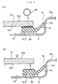
- an eddy current generator 90 such as a coil, is brought near a surface of the glass plate 72 as shown in Fig. 5 (A). This action generates an eddy current in the electrically conductive member 15 to heat the electrically conductive member 15 since the electrically conductive member 15 is embedded in the molding 11 so as to extend parallel to the interior side of the glass plate 72.
- the molding 11 is softened or melted by the heat generation of the electrically conductive member 15 since the molding is molded from thermoplastic resin. It is possible to easily pull only the glass plate 72 off the body panel 70A by lifting the glass plate 72 as shown in Fig. 5 (B) on a phase wherein the molding 11 has been properly softened or melted.
- the eddy current generator 90 there may be used one which extends along the peripheral edge of the glass plate 72 to generate an eddy current in the entire area of the electrically conductive member 15. There may be used a short length of eddy current generator which generates an eddy current only in a portion of the electrically conductive member 15. In that case, the heat that has been generated from that portion of the electrically conductive member 15 by the eddy current can be rapidly transferred to the entire area of the electrically conductive member 15.
- Figs. 6(A) - 6(F) As to the electrically conductive member 15, there are examples shown in Figs. 6(A) - 6(F) as cross-sectional views taken along line VI-VI of Fig. 1.
- the electrically conductive member 15 is formed from a band plate shape of electrically conductive member 15A.
- the electrically conductive member 15 in a strip shape is formed by providing a plurality of filiform electrically conductive members 15B in parallel to each other along a longitudinal direction of the molding 11.
- the electrically conductive member 15 in a strip shape is formed by providing a plurality of short and filiform electrically conductive members 15C in parallel to each other along a width direction of the molding 11.
- the electrically conductive member 15 in a strip shape is formed by providing a plurality of filiform electrically conductive members 15D in parallel to each other so as to extend slantwise with respect to the longitudinal direction of the molding 11.
- the electrically conductive member 15 in a strip shape is formed by providing electrically conductive member 15E having a network shape.
- the electrically conductive member 15 in a strip shape is provided by distributing electrically conductive members 15E having a granular shape in strip fashion.
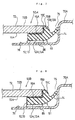
- the transparent plate 50A shown in Fig. 7 comprises the glass plate 72 and a molding 51 fitted to a peripheral portion thereof.
- the molding 51 has an upper attaching portion 12 and lateral attaching portion 13 formed with interior side bonding portions 12A and 13A to be bonded the interior side 72A of the peripheral portion of the glass plate 72 and end face bonding portions 12B and 13B to be bonded the end face 72C of the peripheral portion of the glass plate 72, and the interior side bonding portions 12A and 13A and the end face bonding portions 12B and 13B have different electrically conductive members 15A and 15B embedded therein.
- an eddy current generator such as a coil
- the electrically conductive members 15A on the interior side and the electrically conductive members 15B on the end face side can generate heat therein to soften or melt the molding 51, allowing only the transparent plate 72 to be easily disassembled.
- the electrically conductive member 15A on the interior side and the electrically conductive member 15B of the end face side of the glass plate 72 may be formed by a single electrically conductive member 15C, which has an L-character shape in section and is insert-molded in the molding.
- the electrically conductive member or the electrically conductive members may be also provided as follows. Specifically, the electrically conductive member or the electrically conductive members are provided on the glass plate. Specific examples are one wherein electrically conductive ceramic paste, which contains, e.g., silver, is fired on the glass plate to form a fired member of electrically conductive print thereon, and one wherein an electrically conductive tape is affixed on the glass plate.
- the electrically conductive member or the electrically conductive members are insert-molded in the molding.
- the eddy current generator it is preferable to bring the eddy current generator near the glass plate from an exterior side of the glass plate.
- Table 1 shows data with respect to the case wherein the same coil for generating an eddy current in a portion of each of electrically conductive members was brought near under different conditions in examples (Examples 1 - 7) where a fired member of electrically conductive print (hereinbelow, referred to as "the Ag print") containing silver was provided as the electrically conductive member on the interior side of the peripheral edge of a glass plate (300 mm ⁇ 300 mm), and examples (Examples 8 - 10) where the Ag print was provided as the electrically conductive member on the interior side of the peripheral edge of a glass plate (300 mm ⁇ 300 mm) and was covered. by a molding.
- the Ag print containing silver
- Table 1 also shows data with respect to the case wherein the same coil for generating an eddy current in a portion of each of electrically conductive members was brought near under different conditions in examples (Examples 11 - 13) where the Ag print and the molding for covering the Ag print were provided on the interior side of the peripheral edge of a glass plate (300 mm ⁇ 300 mm), and the combination of the Ag print and the molding was bonded to an iron sheet through an urethane adhesive; and an example (Example 14) where the Ag print and the molding for covering the Ag print were provided on the interior side of the peripheral edge of a glass plate (700 mm ⁇ 400 mm, the actual dimensions of a sidelight), and the combination of the Ag print and the molding was bonded to an iron sheet through an urethane adhesive.
- Example 1 the heating time was set at 5 sec, and the coil position (the distance from the glass plate) was set at 0 mm. The result was that the glass plate was fractured.
- Example 2 the heating time was set at 5 sec, and the coil position was set at 5 mm. The result was that the glass plate was fractured.
- Example 3 the heating time was set at 5 sec, and the coil position was set at 10 mm. The result was that the glass plate was fractured.
- Example 4 the heating time was set at 5 sec, and the coil position was set at 15 mm. The result was that the glass plate had a temperature of 78°C.
- Example 5 the heating time was set at 10 sec, and the coil position was set at 20 mm. The result was that the glass plate had a temperature of 124°C.
- Example 6 the heating time was set at 15 sec, and the coil position was set at 20 mm. The result was that the glass plate had a temperature of 178°C.
- Example 7 the heating time was set at 20 sec, and the coil position was set at 20 mm. The result was that the glass plate had a temperature of 206°C.
- Example 8 the heating time was set at 20 sec, and the coil position was set at 20 mm. The result was that the molding was unstuck from the glass plate.
- Example 9 the heating time was set at 25 sec, and the coil position was set at 20 mm. The result was that the molding was unstuck from the glass plate.
- Example 10 the heating time was set at 30 sec, and the coil position was set at 20 mm. The result was that the molding was unstuck from the glass plate.
- Example 8 the removing force, which was required to unstick each of the moldings, varies from Example to Example. Specifically, the molding in Example 9 was unstuck by a smaller pulling force than that in Example 8, and the molding in Example 10 was unstuck by a smaller pulling force than that in Example 9.
- Example 11 the heating time was set at 30 sec, and the coil position was set at 20 mm. The result was that the glass plate was not disassembled from the iron sheet.
- Example 12 the heating time was set at 30 sec, and the coil position was set at 10 mm. The result was that the glass plate was fractured.
- Example 13 the heating time was set at 30 sec, and the coil position was set at 15 mm. The result was that the glass plate was disassembled from the iron sheet. At that case, the glass plate removing force was 49N.
- Example 14 the heating time was set at 30 sec, and the coil position was set at 15 mm. The result was that the glass plate was disassembled from the iron sheet. At that case, the glass plate removing force was 90N.
- the data reveal that the glass plate can be reliably disassembled by a small force by properly setting the coil position and the heating time.
- the glass plate can be prevented from being fractured due to heat by keeping the coil away from the glass plate by a distance of not less than 15 mm.
- the glass plate can be easily disassembled by setting the heating time at a value of not less than 30 sec.
- the electrically conductive member is required to be heated in sufficient fashion in consideration of heat release to the iron sheet.
- a sealing member made of Butyl-rubber in place of the lip portion 14 as the elastic portion may be interposed between the molding and the window opening.
- the transparent plate are a plate for a backlight and a plate for a sidelight besides a plate for a windshield.
- the molding is unified to the transparent plate when the molding is formed by injection molding.
- the molding may be formed in such a shape that the molding is bonded to the interior and exterior sides and the end face of the transparent plate. In that case, the molding is required to be softened or melted in sufficient fashion in order to disassemble the transparent plate since the molding has the attaching portions formed in a substantially U-character shape in section. It is preferable from the following viewpoint that the molding is formed in such a shape to be bonded only to the interior side and the end face of the transparent plate as in the first to the third embodiments or only to the end face. In other words, when the molding is formed in any one of the shapes in the first to the third embodiments, the molding and the transparent plate are bonded together without being mechanically engaged together. The transparent plate can be easily disassembled when the molding has been softened or melted to some extent. From this viewpoint, it is preferable that the molding is formed in such a shape to be bonded only to the interior side and the end face of the transparent plate or only to the end face.
- the transparent plate examples are a glass plate and a transparent resin plate, such as a polycarbonate plate. From the viewpoint that the transparent plate is also heated, the present invention is in particular effective to a transparent plate made of glass.
- the electrically conductive member is provided on the transparent plate, it is preferable from the viewpoint of production that a fired member of electrically conductive print with silver contained therein is utilized as the electrically conductive member for instance.
- the electrically conductive member is insert-molded in the molding, it is preferable from the viewpoint of handling that the electrically conductive member is made of iron for instance.
- Other examples of the electrically conductive member are copper, aluminum or others.
- the present invention has the electrically conductive member insert-molded in the thermoplastic resin molding to extend substantially parallel to the transparent plate surface.
- the molding which has been bonded and fixed to a window opening of an automobile, can be easily disassembled from the window -opening later. Since bringing the eddy current generator, such as a coil, near a surface of the transparent plate can cause the electrically conductive member to be heated so as to soften or melt the molding, the molding can be broken to easily disassemble the transparent plate, the electrically conductive member serving as a boundary. As a result, it becomes possible to facilitate recycling.
- the molding can be disassembled in much easier fashion since a strip shape of heated region can be formed in the electrically conductive member.
- the electrically conductive member is provided so as not to project from a surface of the molding, the transparent plate can be prevented from having a poor appearance.
Landscapes
- Engineering & Computer Science (AREA)
- Mechanical Engineering (AREA)
- Textile Engineering (AREA)
- Injection Moulding Of Plastics Or The Like (AREA)
- Vehicle Interior And Exterior Ornaments, Soundproofing, And Insulation (AREA)
- Lining Or Joining Of Plastics Or The Like (AREA)
Abstract
A molding includes an attaching portion to be bonded
to an interior side of a peripheral edge of a glass plate
and an elastic portion capable of being in close contact
with a window opening. The molding 11 is made of
thermoplastic resin and has an electrically conductive
member insert-molded therein, the electrically conductive
member extending substantially parallel to a surface of
the glass plate and generating heat by bringing an eddy
current generator near thereto. The eddy current
generator is brought near a surface of the transparent
plate to generate heat in the electrically conductive
member, thereby softening or melting the molding, and an
external force is applied to the transparent plate to
disassemble the transparent plate from the window opening
of an automobile.
Description
The present invention relates to a transparent plate
with a molding and a method for disassembling a
transparent plate, in particular a transparent plate with
a molding for an automobile window and a method for
disassembling a transparent plate for an automobile
window.
As shown in Fig. 9 and 10, a transparent plate with
a molding 71, which is used for the windshield of an
automobile 70, includes a glass plate 72 having a
substantially trapezoidal shape as viewed in a plan view
(when viewed in a plan view) and curved in a two
dimensional direction or a three dimensional direction,
and a resin molding 80 extending along an upper side 73
and both lateral sides 74, 74 forming a peripheral edge
of the glass plate 72. The transparent plate with a
molding 71 is fitted into an opening (window opening) 75
formed in a body panel 70A.
The molding 80 is also called a frame, a gasket or
the like. This specification uses the word "molding".
The upper side 73 of the glass plate 72 means a side
extending along a roof 76 of the automobile 70, and the
lateral sides of the glass plate 72 mean sides extending
along pillars 77 or other members of the automobile 70.
Fig. 11 shows the transparent plate with a molding
71, wherein the molding 80 is bonded only to an interior
side 72A of the glass plate 72 (This structure will be,
hereinbelow, referred to as "one-side molding"). The
molding 80 includes an upper attaching portion 81 and
lateral attaching portions 82 to be bonded to the
interior side 72A along the upper side 73 and the lateral
sides 74 of the glass plate 72, and a lip portion 83
extending in directions away from the upper attaching
portion 81 and the lateral attaching portions 82 with
respect to the glass plate 72.
The transparent plate with a molding 71 is fitted
into and fixed to the opening 75 by a proper adhesive 86
interposed between a surface (on an exterior side) of a
attaching flange 76 of the opening 75 and the molding 80.
In that case, the lip portion 83 is elastically deformed
to be in close contact with a sidewall 75A of the opening,
providing a water proofing property between the opening
75 and the upper and lateral sides 73 and 74 of the glass
plate 72.
The transparent plate with a molding 71 can be
produced by, e.g., an encapsulation method wherein melted
resin is injected into a cavity space of a mold with the
glass plate 72 provided therein to form the molding 80
along the upper side 73 and the lateral sides 74, 74 of
the glass plate 72.
In late years, the glass plate for an automobile 72
has been demanded to be capable of being easily
disassembled from the body panel 70A mainly from the
viewpoint of the recycling of industrial products.
However, it has been impossible to easily disassemble
only the glass plane 72 since the transparent plate with
a molding 71 is assembled to the body panel 70A by an
adhesive in prior art.
It is an object of the present invention to provide
a transparent plate with a molding and a method for
disassembling a transparent plate, which can easily
disassemble a transparent plate for the body panel of an
automobile to facilitate recycling.
The present invention provides a transparent plate
with a molding, which comprises at least a transparent
plate to be assembled to a window opening of an
automobile and a thermoplastic resin molding unified to a
peripheral edge of the transparent plate; the molding
including an attaching portion to be bonded to at least
an interior side of the peripheral edge of the
transparent plate and an elastic portion connected to the
attaching portion so as to be capable of being in close
contact with the window opening; and which is
characterized in that the molding has an electrically
conductive member insert-molded therein, the electrically
conductive member extending substantially parallel to a
transparent plate surface.
The transparent plate surface means an interior side
of the transparent plate in the case of one-side molding,
and an interior side and end faces of the transparent
plate in the case of bonding the molding to the interior
side and the end faces of the transparent plate. In the
case of bonding the molding to the interior side and the
end faces of the transparent plate, the electrically
conductive member is provided to extend parallel to each
of the interior side and the end faces of the transparent
plate. In that case, the electrically conductive member
of the interior side and the electrically conductive
member of the end faces may be embedded in the molding
independently of each other or be embedded in the molding
as an integral part wherein both electrically conductive
members are formed in continuous fashion to have a
substantially L-character shape in section.
Examples of the electrically conductive member are a
band plate shape of electrically conductive member and an
electrically conductive member having granular shape or
bar shape of portions distributed along a single surface.
In accordance with the present invention stated
earlier, the molding is made of thermoplastic resin, and
the molding has the electrically conductive member
insert-molded therein, the electrically conductive member
extending substantially parallel to the transparent plate
surface. When the transparent plate is required to be
disassembled from the window opening, an eddy current
generator, such as a coil, can be brought near a surface
of the transparent plate and heat the electrically
conductive member by an eddy current generated therein to
soften or melt the molding. In this manner, the
transparent plate can be easily disassembled since the
molding can be broken, the electrically conductive member
serving as a boundary.
It is preferable that the electrically conductive
member is a substantially strip shape of electrically
conductive member. In this mode of the present invention,
the molding can be softened or melted more efficiently
since an eddy current generator, such as a coil, can be
brought near a surface of the transparent plate to form a
strip shape of heated region in the electrically
conductive member.
It is preferable that the electrically conductive
member is provided so as not to project from a surface of
the molding. In this mode of the present invention, the
transparent plate can be prevented from having a poor
appearance since the electrically conductive member is
fully embedded in the molding in such fashion to be
invisible from outside. When the electrically conductive
portion is provided to project from a surface of the
molding, generated heat can be transferred to another
member in touch with the molding in some cases. When the
electrically conductive member is fully embedded in the
molding, the generated heat can be effectively utilized
for softening or melting the molding.
The present invention also provides a method for
disassembling a transparent plate with a thermoplastic
resin molding unified to a peripheral edge thereof
from a window opening of an automobile with the
transparent plate assembled thereto by heating the
molding, which is characterized in that the method
comprises preliminarily providing the transparent plate
with an electrically conductive member so as to cover at
least one portion of the electrically conductive member
with the molding, the electrically conductive member
extending substantially parallel to a transparent plate
surface; bringing an eddy current generator near a
surface of the transparent plate to generate heat in the
electrically conductive member, thereby softening or
melting the molding; and applying an external force to
the transparent plate to disassemble the transparent
plate from the window opening of the automobile.
In accordance with the present invention, in order
to disassemble the transparent plate from the window
opening, it is sufficient only to bring the eddy current
generator near a surface of the transparent plate and
generate heat in the electrically conductive member to
soften or melt the molding. As a result, it is possible
to easily disassemble the transparent plate from the
window opening of the automobile.
Now, embodiments of the present invention will be
described in detail in reference to the accompanying
drawings. In the explanation of the embodiments, parts
similar to the parts explained with respect to Fig. 10 or
Fig. 11 are indicated by identical or corresponding
reference numerals in the drawings, and explanation of
these parts will be simplified or omitted.
As shown in Fig. 1 and Fig. 2, the transparent plate
with a molding 10 according to a first embodiment has a
molding 11 provided thereto so as to extend an upper side
73 and lateral sides 74 as a peripheral edge of a glass
plate 72. The transparent plate with a molding 10 is
utilized as the windshield of an automobile.
The molding 11 includes an upper attaching portion
12 and lateral attaching portions 13 to be continuously
bonded to an interior side 72A along the upper side 73
and the lateral sides 74 of the glass plate 72, and a lip
portion 14 continuously extending from the attaching
portions 12, 13 to be in close contact with a sidewall
75A of an opening.
The molding 11 is molded from thermoplastic resin,
and the upper attaching portion 12 and the lateral
attaching portions 13 have an electrically conductive
member 15 insert-molded therein in continuous fashion,
the electrically conductive member extending
substantially parallel to the interior side 72A of the
glass plate 72 and along a longitudinal direction of the
molding 11. The electrically conductive member 15
comprises a substantially band plate shape of
electrically conductive member or a strip shape of
electrically conductive member, and the electrically
conductive member is provided so as not to project from a
surface of the molding 11. Although a sheet of silver
foil is most suited to form the electrically conductive
member, a sheet of copper or aluminum foil, a band plate
or the like may be utilized.
The electrically conductive member 15, which is
insert-molded in the molding, has a thickness of, e.g.,
1-2 mm in order to prevent the flexibility of the molding
from degrading.
The transparent plate with a molding 10 is engaged
into and fixed to an opening 75 of a body panel 70A by
using an adhesive 86 to bond the upper attaching portion
12 and the lateral attaching portions 13 of the molding
11 to a surface of an attaching flange 76 extending
substantially parallel to the interior side 72A of the
glass plate 72.
The molding 11 can be produced by continuously
extruding an upper side molding portion and lateral side
molding portions from, e.g., an extrusion molding die 30
shown in Fig. 3.
The extrusion molding die 30 includes a die main
body 31 and a forming space 32 provided in the die main
body 31. The extrusion molding die 30 extrudes a resin
material so as to pass the material through the forming
space 32 from a rear end toward a front end in this
figure, producing the molding 11 in a desired cross-sectional
shape. By supplying the electrically
conductive member to the extrusion molding die
concurrently with extrusion of the resin material, the
molding 11 can be formed so as to have the electrically
conductive member 15 insert-molded therein.
The resin used for the molding 11 is thermoplastic
resin, such as polyvinyl chloride, a copolymer of vinyl
chloride and ethylene, a styrene type elastomer, an
olefin type elastomer, urethane resin, silicone resin, or
vinyl chloride resin in a sol state.
The transparent plate with a molding 10 may be
produced by a method wherein the molding 11 extruded from
the extrusion molding die 30 is directly fitted to the
upper side 73 and the lateral sides 74 of the glass plate
72 by moving or rotating the glass plate 72.
As specifically shown in Fig. 4, the glass plate 72,
which has preliminarily had a primer (not shown) applied
on the upper side 73 and the lateral sides 74, is
supported by a supporting arm 40, and the molding 11,
which has been extruded from an extruder 41 through the
extrusion molding die 30, is supported by a pressing
member 42.
The supporting arm 40 can move in a three
dimensional direction, support the glass plate 72 at an
arbitrary angle through suckers 43 provided on a leading
edge of the supporting arm 40, and rotate the glass plate
72 about a line extending in the thickness direction of
the glass plate 72. The upper attaching portion 12 and
the lateral attaching portions 13 of the molding 11,
which have been extruded from the extrusion molding die
30, are pressed against the interior side of the glass
plate 72 to be bonded thereto by the pressing member 42.
The molding 11 is sequentially fitted to the upper
side 73 and the lateral sides 74 of the glass plate 73 by
rotating the glass plate 72 while providing the
supporting arm 40 and the respective suckers 43 with
cooperative movement so as to relatively move the
pressing member 42 with respect to the upper side 73 and
the lateral sides 74 of the glass plate 72.
At that time, the provision of the primer, which has
been preliminarily applied on the upper side 73 and the
lateral sides 74 of the glass plate 72, ensures that the
molding 11 is fitted. The molding 11 thus fitted to the
glass plate 72 may be quenched by jets of air 45 emitted
from a nozzle 44.
Now, a method for disassembling the transparent
plate with a molding 10 from the body panel 70A will be
explained.
When the transparent plate with a molding 10 is
disassembled from-the body panel 70A for recycling or
another purpose, an eddy current generator 90, such as a
coil, is brought near a surface of the glass plate 72 as
shown in Fig. 5 (A). This action generates an eddy
current in the electrically conductive member 15 to heat
the electrically conductive member 15 since the
electrically conductive member 15 is embedded in the
molding 11 so as to extend parallel to the interior side
of the glass plate 72. The molding 11 is softened or
melted by the heat generation of the electrically
conductive member 15 since the molding is molded from
thermoplastic resin. It is possible to easily pull only
the glass plate 72 off the body panel 70A by lifting the
glass plate 72 as shown in Fig. 5 (B) on a phase wherein
the molding 11 has been properly softened or melted.
As explained, it is possible to easily disassemble
the transparent plate with a molding 10 by only the
provision of the eddy current generator 90, such as a
coil, without using a special tool or device. It is
possible to quickly forward only the glass plate 72 to a
recycling process.
As the eddy current generator 90, there may be used
one which extends along the peripheral edge of the glass
plate 72 to generate an eddy current in the entire area
of the electrically conductive member 15. There may be
used a short length of eddy current generator which
generates an eddy current only in a portion of the
electrically conductive member 15. In that case, the
heat that has been generated from that portion of the
electrically conductive member 15 by the eddy current can
be rapidly transferred to the entire area of the
electrically conductive member 15.
As to the electrically conductive member 15, there
are examples shown in Figs. 6(A) - 6(F) as cross-sectional
views taken along line VI-VI of Fig. 1.
In the one shown in (A), the electrically conductive
member 15 is formed from a band plate shape of
electrically conductive member 15A.
In the one shown in (B), the electrically conductive
member 15 in a strip shape is formed by providing a
plurality of filiform electrically conductive members 15B
in parallel to each other along a longitudinal direction
of the molding 11.
In the one shown in (C), the electrically conductive
member 15 in a strip shape is formed by providing a
plurality of short and filiform electrically conductive
members 15C in parallel to each other along a width
direction of the molding 11.
In the one shown in (D), the electrically conductive
member 15 in a strip shape is formed by providing a
plurality of filiform electrically conductive members 15D
in parallel to each other so as to extend slantwise with
respect to the longitudinal direction of the molding 11.
In the one shown in (E), the electrically conductive
member 15 in a strip shape is formed by providing
electrically conductive member 15E having a network shape.
In the one shown in (F), the electrically conductive
member 15 in a strip shape is provided by distributing
electrically conductive members 15E having a granular
shape in strip fashion.
Although explanation of the first embodiment has
been made with respect to the case of one-side molding,
the present invention is also applicable to a case
wherein the molding is bonded to the interior side and
end face of the peripheral edge of the glass plate. This
example is shown as a second embodiment in Fig. 7. In
the explanation of the embodiments stated below, parts
similar to the parts explained with respect to Fig. 1 or
Fig. 2 are indicated by identical or corresponding
reference numerals in the drawings, and explanation of
these parts will be simplified or omitted.
The transparent plate 50A shown in Fig. 7 comprises
the glass plate 72 and a molding 51 fitted to a
peripheral portion thereof.
The molding 51 has an upper attaching portion 12 and
lateral attaching portion 13 formed with interior side
bonding portions 12A and 13A to be bonded the interior
side 72A of the peripheral portion of the glass plate 72
and end face bonding portions 12B and 13B to be bonded
the end face 72C of the peripheral portion of the glass
plate 72, and the interior side bonding portions 12A and
13A and the end face bonding portions 12B and 13B have
different electrically conductive members 15A and 15B
embedded therein.
When the transparent plate 50A is disassembled from
the body panel 70A, an eddy current generator, such as a
coil, is brought near a surface of the transparent plate
72A as well. Thus, the electrically conductive members
15A on the interior side and the electrically conductive
members 15B on the end face side can generate heat
therein to soften or melt the molding 51, allowing only
the transparent plate 72 to be easily disassembled.
As the transparent plate 50B according to a third
embodiment shown in Fig. 8, the electrically conductive
member 15A on the interior side and the electrically
conductive member 15B of the end face side of the glass
plate 72 may be formed by a single electrically
conductive member 15C, which has an L-character shape in
section and is insert-molded in the molding.
In the three embodiments, illustration has been made
with respect to the case wherein the electrically
conductive member or the electrically conductive members
are embedded in the molding. Since the method for
disassembling a transparent plate according to the
present invention provides a simple disassembling method
to utilize the generation of eddy currents to heat the
electrically conductive member or the electrically
conductive members, the electrically conductive member or
the electrically conductive members may be also provided
as follows. Specifically, the electrically conductive
member or the electrically conductive members are
provided on the glass plate. Specific examples are one
wherein electrically conductive ceramic paste, which
contains, e.g., silver, is fired on the glass plate to
form a fired member of electrically conductive print
thereon, and one wherein an electrically conductive tape
is affixed on the glass plate.
From the viewpoint that the generation of heat in
the electrically conductive member or the electrically
conductive members can be effectively utilized for
softening or melting of the molding, it is preferable
that the electrically conductive member or the
electrically conductive members are insert-molded in the
molding.
In the present invention, it is preferable to bring
the eddy current generator near the glass plate from an
exterior side of the glass plate. In order to
effectively generate the eddy current in the electrically
conductive member, it is preferable to locate the eddy
current generator so as to confront a portion of the
glass plate where the molding is fitted. The reason is
that it is difficult to bring the eddy current generator
near the glass plate from the interior side of the
portion of the glass plate where the molding is fitted.
The effectiveness of the method for disassembling a
transparent plate according to the present invention will
be described by examples in the case of provision of an
electrically conductive member on a glass plate. Table 1
shows data with respect to the case wherein the same coil
for generating an eddy current in a portion of each of
electrically conductive members was brought near under
different conditions in examples (Examples 1 - 7) where a
fired member of electrically conductive print
(hereinbelow, referred to as "the Ag print") containing
silver was provided as the electrically conductive member
on the interior side of the peripheral edge of a glass
plate (300 mm × 300 mm), and examples (Examples 8 - 10)
where the Ag print was provided as the electrically
conductive member on the interior side of the peripheral
edge of a glass plate (300 mm × 300 mm) and was covered.
by a molding.
Table 1 also shows data with respect to the case
wherein the same coil for generating an eddy current in a
portion of each of electrically conductive members was
brought near under different conditions in examples
(Examples 11 - 13) where the Ag print and the molding for
covering the Ag print were provided on the interior side
of the peripheral edge of a glass plate (300 mm × 300 mm),
and the combination of the Ag print and the molding was
bonded to an iron sheet through an urethane adhesive; and
an example (Example 14) where the Ag print and the
molding for covering the Ag print were provided on the
interior side of the peripheral edge of a glass plate
(700 mm × 400 mm, the actual dimensions of a sidelight),
and the combination of the Ag print and the molding was
bonded to an iron sheet through an urethane adhesive.
| Heating time in sec. | Coil position | Glass temperature | Removing force | Remark | |
| Ex. 1 | 5 seconds | 0 | - | - | Glass fractured |
| Ex. 2 | 5 seconds | 5 mm | - | - | Glass fractured |
| Ex. 3 | 5 | 10 mm | - | - | Glass fractured |
| Ex. 4 | 5 | 15 mm | 78°C | - | |
| Ex. 5 | 10 seconds | 20 mm | 124°C | - | |
| Ex. 6 | 15 seconds | 20 mm | 178°C | - | |
| Ex. 7 | 20 seconds | 20 mm | 206°C | - | |
| Ex. 8 | 20 seconds | 20 mm | - | - | Unstuck |
| Ex. 9 | 25 seconds | 20 mm | - | - | Unstuck |
| Ex. 10 | 30 seconds | 20 mm | - | - | Unstuck |
| Ex. 11 | 30 seconds | 20 mm | - | - | |
| Ex. 12 | 30 | 10 mm | - | - | Glass fractured |
| Ex. 13 | 30 | 15 mm | - | 49N | Disassembled |
| Ex. 14 | 30 | 15 mm | - | 90N | Disassembled |
In Example 1, the heating time was set at 5 sec, and
the coil position (the distance from the glass plate) was
set at 0 mm. The result was that the glass plate was
fractured.
In Example 2, the heating time was set at 5 sec, and
the coil position was set at 5 mm. The result was that
the glass plate was fractured.
In Example 3, the heating time was set at 5 sec, and
the coil position was set at 10 mm. The result was that
the glass plate was fractured.
In Example 4, the heating time was set at 5 sec, and
the coil position was set at 15 mm. The result was that
the glass plate had a temperature of 78°C.
In Example 5, the heating time was set at 10 sec,
and the coil position was set at 20 mm. The result was
that the glass plate had a temperature of 124°C.
In Example 6, the heating time was set at 15 sec,
and the coil position was set at 20 mm. The result was
that the glass plate had a temperature of 178°C.
In Example 7, the heating time was set at 20 sec,
and the coil position was set at 20 mm. The result was
that the glass plate had a temperature of 206°C.
In Example 8, the heating time was set at 20 sec,
and the coil position was set at 20 mm. The result was
that the molding was unstuck from the glass plate.
In Example 9, the heating time was set at 25 sec,
and the coil position was set at 20 mm. The result was
that the molding was unstuck from the glass plate.
In Example 10, the heating time was set at 30 sec,
and the coil position was set at 20 mm. The result was
that the molding was unstuck from the glass plate.
In Examples 8 - 10, the removing force, which was
required to unstick each of the moldings, varies from
Example to Example. Specifically, the molding in Example
9 was unstuck by a smaller pulling force than that in
Example 8, and the molding in Example 10 was unstuck by a
smaller pulling force than that in Example 9.
In Example 11, the heating time was set at 30 sec,
and the coil position was set at 20 mm. The result was
that the glass plate was not disassembled from the iron
sheet.
In Example 12, the heating time was set at 30 sec,
and the coil position was set at 10 mm. The result was
that the glass plate was fractured.
In Example 13, the heating time was set at 30 sec,
and the coil position was set at 15 mm. The result was
that the glass plate was disassembled from the iron sheet.
At that case, the glass plate removing force was 49N.
In Example 14, the heating time was set at 30 sec,
and the coil position was set at 15 mm. The result was
that the glass plate was disassembled from the iron sheet.
At that case, the glass plate removing force was 90N.
The data reveal that the glass plate can be reliably
disassembled by a small force by properly setting the
coil position and the heating time. In particular, the
glass plate can be prevented from being fractured due to
heat by keeping the coil away from the glass plate by a
distance of not less than 15 mm. The glass plate can be
easily disassembled by setting the heating time at a
value of not less than 30 sec.
In the cases of fitting the molding to the iron sheet
by the adhesive, it is revealed that the electrically
conductive member is required to be heated in sufficient
fashion in consideration of heat release to the iron
sheet.
The present invention is not limited to the
respective embodiments stated earlier, and proper
modification or improvement can be made in the present
invention.
For example, a sealing member made of Butyl-rubber
in place of the lip portion 14 as the elastic portion may
be interposed between the molding and the window opening.
Examples of the transparent plate are a plate for a
backlight and a plate for a sidelight besides a plate for
a windshield. As another method for unifying the molding
to the transparent plate, there is a method wherein the
molding is unified to the transparent plate when the
molding is formed by injection molding.
The molding may be formed in such a shape that the
molding is bonded to the interior and exterior sides and
the end face of the transparent plate. In that case, the
molding is required to be softened or melted in
sufficient fashion in order to disassemble the
transparent plate since the molding has the attaching
portions formed in a substantially U-character shape in
section. It is preferable from the following viewpoint
that the molding is formed in such a shape to be bonded
only to the interior side and the end face of the
transparent plate as in the first to the third
embodiments or only to the end face. In other words,
when the molding is formed in any one of the shapes in
the first to the third embodiments, the molding and the
transparent plate are bonded together without being
mechanically engaged together. The transparent plate can
be easily disassembled when the molding has been softened
or melted to some extent. From this viewpoint, it is
preferable that the molding is formed in such a shape to
be bonded only to the interior side and the end face of
the transparent plate or only to the end face.
Examples of the transparent plate are a glass plate
and a transparent resin plate, such as a polycarbonate
plate. From the viewpoint that the transparent plate is
also heated, the present invention is in particular
effective to a transparent plate made of glass. When the
electrically conductive member is provided on the
transparent plate, it is preferable from the viewpoint of
production that a fired member of electrically conductive
print with silver contained therein is utilized as the
electrically conductive member for instance. When the
electrically conductive member is insert-molded in the
molding, it is preferable from the viewpoint of handling
that the electrically conductive member is made of iron
for instance. Other examples of the electrically
conductive member are copper, aluminum or others.
As explained, the present invention has the
electrically conductive member insert-molded in the
thermoplastic resin molding to extend substantially
parallel to the transparent plate surface. As a result,
the molding, which has been bonded and fixed to a window
opening of an automobile, can be easily disassembled from
the window -opening later. Since bringing the eddy
current generator, such as a coil, near a surface of the
transparent plate can cause the electrically conductive
member to be heated so as to soften or melt the molding,
the molding can be broken to easily disassemble the
transparent plate, the electrically conductive member
serving as a boundary. As a result, it becomes possible
to facilitate recycling.
When the electrically conductive member is a
substantially strip shape of electrically conductive
member in the present invention, the molding can be
disassembled in much easier fashion since a strip shape
of heated region can be formed in the electrically
conductive member. When the electrically conductive
member is provided so as not to project from a surface of
the molding, the transparent plate can be prevented from
having a poor appearance.
In order to disassemble the transparent plate from
the window opening, it is sufficient only to bring the
eddy current generator near a surface of the transparent
plate and generate heat in the electrically conductive
member to soften or melt the molding. It is possible to
facilitate recycling since it is possible to easily
disassemble only the transparent plate as stated earlier.
Claims (11)
- A transparent plate with a molding, which comprises at least a transparent plate to be assembled to a window opening of an automobile and a thermoplastic resin molding unified to a peripheral edge of the transparent plate; and
the molding including an attaching portion to be bonded to at least an interior side of the peripheral edge of the transparent plate and an elastic portion connected to the attaching portion so as to be capable of being in close contact with the window opening;
characterized in that the molding has an electrically conductive member insert-molded therein, the electrically conductive member extending substantially parallel to a transparent plate surface. - The transparent plate according to Claim 1, wherein the electrically conductive member is a substantially strip shape of electrically conductive member.
- The transparent plate according to Claim 1 or 2, wherein the electrically conductive portion is provided so as not to project from a surface of the molding.
- The transparent plate according to Claim 1 or 2, wherein the attaching portion of the molding is bonded only to an interior side of the peripheral portion of the transparent plate or only to an interior side and an end face of the peripheral portion of the transparent plate.
- A method for disassembling a transparent plate with a thermoplastic resin molding unified to a peripheral edge thereof from a window opening of an automobile with the transparent plate assembled thereto by heating the molding, characterized in that the method comprises:preliminarily providing the transparent plate with an electrically conductive member so as to cover at least one portion of the electrically conductive member with the molding, the electrically conductive member extending substantially parallel to a transparent plate surface; andbringing an eddy current generator near a surface of the transparent plate to generate heat in the electrically conductive member, thereby softening or melting the molding, and applying an external force to the transparent plate to disassemble the transparent plate from the window opening of the automobile.
- The method according to Claim 4 or 5, further comprising bringing the eddy current generator near from an exterior side of the transparent plate.
- The method according to Claim 4, 5 or 6, further comprising insert-molding the electrically conductive member in the molding.
- The method according to Claim 4, 5, 6 or 7, further comprising providing the electrically conductive member so as not to project from a surface of the molding.
- The method according to Claim 4, 5, 6, 7 or 8, wherein the electrically conductive member is a substantially strip shape of electrically conductive member.
- The method according to Claim 4, 5, 6, 7, 8 or 9, further comprising bringing the eddy current generator near the transparent plate with a distance of not less than 15 mm kept therebetween.
- The method according to Claim 4, 5, 6, 7, 8, 9 or 10, further comprising energizing the eddy current generator for less than 30 sec to generate heat in the electrically conductive member.
Applications Claiming Priority (3)
| Application Number | Priority Date | Filing Date | Title |
|---|---|---|---|
| JP35466699 | 1999-12-14 | ||
| JP35466699 | 1999-12-14 | ||
| PCT/JP2000/008818 WO2001044004A1 (en) | 1999-12-14 | 2000-12-13 | Transparent plate with molding, and method of removing transparent plate |
Publications (2)
| Publication Number | Publication Date |
|---|---|
| EP1238839A1 true EP1238839A1 (en) | 2002-09-11 |
| EP1238839A4 EP1238839A4 (en) | 2005-04-27 |
Family
ID=18439099
Family Applications (1)
| Application Number | Title | Priority Date | Filing Date |
|---|---|---|---|
| EP00981688A Withdrawn EP1238839A4 (en) | 1999-12-14 | 2000-12-13 | TRANSPARENT DISC WITH A MOLDING STRIP AND METHOD FOR REMOVING THE TRANSPARENT DISC |
Country Status (3)
| Country | Link |
|---|---|
| US (1) | US7000356B2 (en) |
| EP (1) | EP1238839A4 (en) |
| WO (1) | WO2001044004A1 (en) |
Families Citing this family (18)
| Publication number | Priority date | Publication date | Assignee | Title |
|---|---|---|---|---|
| US7273135B2 (en) * | 2001-02-15 | 2007-09-25 | Integral Technologies, Inc. | Low cost magnetic brakes and motion control devices manufactured from conductive loaded resin-based materials |
| GB2397609B (en) * | 2003-01-23 | 2006-05-17 | Gdx Automotive Rehburg Gmbh & | Panel-shaped members with strips joined to them, and associated methods |
| DE10355896B4 (en) * | 2003-11-29 | 2006-03-16 | Daimlerchrysler Ag | Attaching a film-coated vehicle glass pane to an opening edge of a vehicle body |
| DE102004059959A1 (en) * | 2004-12-13 | 2006-06-29 | Webasto Ag | Component for the glazing of a building |
| JP5199661B2 (en) * | 2005-02-24 | 2013-05-15 | 日本板硝子株式会社 | Window plate |
| US7950716B2 (en) * | 2008-02-27 | 2011-05-31 | Creative Extruded Products, Inc. | Trim molding for a motor vehicle window panel |
| US8790771B2 (en) * | 2012-10-12 | 2014-07-29 | Agc Automotive Americas R&D, Inc. | Encapsulants for window assemblies |
| JP5913080B2 (en) * | 2012-12-25 | 2016-04-27 | 川崎重工業株式会社 | Separation mechanism of space structure |
| US10883303B2 (en) * | 2013-01-07 | 2021-01-05 | WexEnergy LLC | Frameless supplemental window for fenestration |
| US10196850B2 (en) * | 2013-01-07 | 2019-02-05 | WexEnergy LLC | Frameless supplemental window for fenestration |
| US9663983B2 (en) | 2013-01-07 | 2017-05-30 | WexEnergy LLC | Frameless supplemental window for fenestration incorporating infiltration blockers |
| US9845636B2 (en) * | 2013-01-07 | 2017-12-19 | WexEnergy LLC | Frameless supplemental window for fenestration |
| US9691163B2 (en) | 2013-01-07 | 2017-06-27 | Wexenergy Innovations Llc | System and method of measuring distances related to an object utilizing ancillary objects |
| EP3078642B1 (en) * | 2013-12-03 | 2020-08-19 | Nippon Sheet Glass Company, Limited | Glass plate and method for producing glass plate |
| US10562274B1 (en) * | 2016-02-22 | 2020-02-18 | Apple Inc. | Glass fastening and sealing systems |
| CA3071106A1 (en) | 2017-05-30 | 2018-12-06 | WexEnergy LLC | Frameless supplemental window for fenestration |
| US10369774B2 (en) * | 2017-06-30 | 2019-08-06 | Microsoft Technology Licensing, Llc | Thermally conductive de-bonding aid |
| US11084955B2 (en) | 2018-07-23 | 2021-08-10 | Microsoft Technology Licensing, Llc | Pressure sensitive adhesive with thermally conductive release tab |
Family Cites Families (26)
| Publication number | Priority date | Publication date | Assignee | Title |
|---|---|---|---|---|
| US3514916A (en) * | 1969-05-29 | 1970-06-02 | Goodyear Tire & Rubber | Sealing strip |
| JPS58173619A (en) * | 1982-04-07 | 1983-10-12 | Nissan Shatai Co Ltd | Bonding method for joining parts of vehicle |
| US4551372A (en) * | 1983-03-31 | 1985-11-05 | Saint-Gobain Vitrage | Laminated safety glass |
| FR2547345B1 (en) * | 1983-06-10 | 1986-11-14 | Boussois Sa | GLAZING READY FOR INSTALLATION IN PARTICULAR FOR AUTOMOTIVE |
| DE3501490A1 (en) | 1985-01-18 | 1986-07-24 | Daimler-Benz Ag, 7000 Stuttgart | GLASS DISC GLUED IN THE FRAME OF A CAR BODY BY MEANS OF AN ELASTOMER NETWORKED ADHESIVE |
| US4833847A (en) * | 1987-03-12 | 1989-05-30 | Toyoda Gosei Co., Ltd. | Flush mounting molding |
| DE3818930A1 (en) * | 1988-06-03 | 1989-12-14 | Ver Glaswerke Gmbh | METHOD FOR PREPARING A PRE-ASSEMBLED AUTO GLASS DISC FOR INSTALLATION |
| US5384995A (en) * | 1989-09-12 | 1995-01-31 | St. Gobain Vitrage International | Spacer for windshield bracket |
| ES2018089B3 (en) * | 1987-10-14 | 1991-03-16 | Gurit-Essex Ag | VEHICLE DISC FOR DIRECT GLAZING, PROCEDURE FOR ITS MANUFACTURE AND USE OF THE VEHICLE DISC AS A PREFABRICATED ASSEMBLY PART. |
| CH676345A5 (en) * | 1988-07-15 | 1991-01-15 | Gurit Essex Ag | |
| JP2993974B2 (en) * | 1989-08-10 | 1999-12-27 | 旭硝子株式会社 | How to attach gasket or molding to glass plate |
| US5095669A (en) * | 1989-12-13 | 1992-03-17 | Saint Gobain Vitrage International | Spacer for windshield bracket |
| DE4100631A1 (en) * | 1991-01-11 | 1992-07-16 | Ver Glaswerke Gmbh | CAR GLASS DISC PREPARED FOR ASSEMBLY BY GLUE |
| US5620794A (en) * | 1992-07-01 | 1997-04-15 | Gurit-Essex Ag | Releasable adhesive joint, a method for establishing a releasable adhesive joint and an apparatus for releasing such adhesive joints |
| JP3260559B2 (en) * | 1993-07-23 | 2002-02-25 | 旭硝子株式会社 | How to remove the window plate from the frame |
| JP3310126B2 (en) * | 1994-02-28 | 2002-07-29 | 東海興業株式会社 | Manufacturing method of panel with frame |
| GB9424659D0 (en) * | 1994-12-07 | 1995-02-01 | Belron Int Nv | Releasing of bonded screens |
| DE4445095A1 (en) * | 1994-12-16 | 1996-06-20 | Thaelmann Schwermaschbau Veb | Method for non-destructive parting of adhesive joints |
| DE19511657A1 (en) * | 1995-03-30 | 1996-10-02 | Thaelmann Schwermaschbau Veb | Induction assembly to separate parts from vehicle chassis for recycling |
| DE19537436C2 (en) * | 1995-10-07 | 2002-01-31 | Sekurit Saint Gobain Deutsch | Glass pane pre-equipped for adhesive attachment, especially for vehicles |
| JP3654385B2 (en) * | 1996-06-17 | 2005-06-02 | 旭硝子株式会社 | Method for manufacturing plate-like body with resin frame |
| ES2152060T3 (en) * | 1996-08-22 | 2001-01-16 | Volkswagen Ag | FIXING A WINDOW MOON IN A MOTOR VEHICLE. |
| JPH10166855A (en) * | 1996-12-09 | 1998-06-23 | Honda Motor Co Ltd | Vehicle glass adhesive |
| DE19822044A1 (en) * | 1998-05-16 | 2000-01-13 | Daimler Chrysler Ag | Adhesive connection |
| DE19843843C2 (en) * | 1998-09-24 | 2001-08-30 | Saint Gobain Sekurit D Gmbh | Window pane with a profile strand comprising a gap cover |
| US6513854B2 (en) * | 2001-02-15 | 2003-02-04 | Centre Luxembourgeois De Recherches Pour Le Verre Et La Ceramique S.A. (C.R.V.C.) | Method of applying extruded profile to corners of a window glazing |
-
2000
- 2000-12-13 WO PCT/JP2000/008818 patent/WO2001044004A1/en not_active Ceased
- 2000-12-13 EP EP00981688A patent/EP1238839A4/en not_active Withdrawn
-
2002
- 2002-06-14 US US10/170,383 patent/US7000356B2/en not_active Expired - Fee Related
Also Published As
| Publication number | Publication date |
|---|---|
| US20030005563A1 (en) | 2003-01-09 |
| EP1238839A4 (en) | 2005-04-27 |
| US7000356B2 (en) | 2006-02-21 |
| WO2001044004A1 (en) | 2001-06-21 |
Similar Documents
| Publication | Publication Date | Title |
|---|---|---|
| US7000356B2 (en) | Transparent plate with a molding and method for disassembling transparent plate | |
| RU2299808C2 (en) | Method of production of the plastic window glass with the electroconductive structure and the plastic window glass with the built-in wires | |
| US4555607A (en) | Process for installation and removal of glass pane from a frame | |
| EP0576180B1 (en) | Vehicular panel assembly | |
| EP0371810B1 (en) | Window for automobiles or the like, and method of manufacturing the same | |
| JPH0367487B2 (en) | ||
| JP3043684B2 (en) | Injection molding simultaneous painting equipment | |
| US5786047A (en) | Bodyside molding with bright insert and method of making same | |
| CN111554191A (en) | Laminating device and laminating method | |
| CN102234486B (en) | Hot melt adhesive unit of adhesive bonding structure | |
| EP1238786B1 (en) | Method for producing a plate-like body attached with a resin frame | |
| US6607622B2 (en) | Method of applying an extruded profile to a window glazing | |
| US5846465A (en) | Method for preparing a plate member for a window with a resinous frame | |
| WO2023274410A1 (en) | Dimming component and manufacturing method therefor, light-transmitting assembly, and vehicle | |
| JPS6038250B2 (en) | Injection molding method for laminated molded products | |
| JP2010115926A (en) | Method of manufacturing plastic window glass having electric conductor structure and plastic window glass having embedded wire | |
| JP2009012219A (en) | Manufacturing method of synthetic resin molded products | |
| CZ216594A3 (en) | Laminated glazing system and process and apparatus for making thereof | |
| JPWO2001044004A1 (en) | How to remove the clear panel with molding and the clear panel | |
| JP4408602B2 (en) | Decorative film | |
| US20020076527A1 (en) | Panel units having in situ formed moldings | |
| JP3540601B2 (en) | Method for manufacturing panel with frame | |
| JP3212011B2 (en) | Panel with frame and manufacturing method thereof | |
| JPH10180798A (en) | Injection molding simultaneous painting apparatus and method | |
| JPH08309818A (en) | Method for manufacturing plate material for window with resin frame |
Legal Events
| Date | Code | Title | Description |
|---|---|---|---|
| PUAI | Public reference made under article 153(3) epc to a published international application that has entered the european phase |
Free format text: ORIGINAL CODE: 0009012 |
|
| 17P | Request for examination filed |
Effective date: 20020613 |
|
| AK | Designated contracting states |
Kind code of ref document: A1 Designated state(s): AT BE CH CY DE DK ES FI FR GB GR IE IT LI LU MC NL PT SE TR |
|
| A4 | Supplementary search report drawn up and despatched |
Effective date: 20050311 |
|
| STAA | Information on the status of an ep patent application or granted ep patent |
Free format text: STATUS: THE APPLICATION IS DEEMED TO BE WITHDRAWN |
|
| 18D | Application deemed to be withdrawn |
Effective date: 20050518 |