EP1238624A2 - Intra-oral camera with integral display - Google Patents
Intra-oral camera with integral display Download PDFInfo
- Publication number
- EP1238624A2 EP1238624A2 EP02075645A EP02075645A EP1238624A2 EP 1238624 A2 EP1238624 A2 EP 1238624A2 EP 02075645 A EP02075645 A EP 02075645A EP 02075645 A EP02075645 A EP 02075645A EP 1238624 A2 EP1238624 A2 EP 1238624A2
- Authority
- EP
- European Patent Office
- Prior art keywords
- image
- base
- handpiece
- intra
- oral
- Prior art date
- Legal status (The legal status is an assumption and is not a legal conclusion. Google has not performed a legal analysis and makes no representation as to the accuracy of the status listed.)
- Granted
Links
- 230000002093 peripheral effect Effects 0.000 claims abstract description 22
- 210000000214 mouth Anatomy 0.000 claims abstract description 12
- 238000012545 processing Methods 0.000 claims abstract description 10
- 230000003287 optical effect Effects 0.000 claims abstract description 7
- 238000003780 insertion Methods 0.000 claims abstract description 5
- 230000037431 insertion Effects 0.000 claims abstract description 5
- 238000012552 review Methods 0.000 claims abstract description 4
- 238000003032 molecular docking Methods 0.000 claims description 20
- 238000012546 transfer Methods 0.000 claims description 6
- 230000000977 initiatory effect Effects 0.000 claims description 5
- 230000015654 memory Effects 0.000 description 10
- 238000005286 illumination Methods 0.000 description 8
- 238000005516 engineering process Methods 0.000 description 7
- 238000000034 method Methods 0.000 description 6
- 230000008901 benefit Effects 0.000 description 5
- 238000004891 communication Methods 0.000 description 5
- 238000013500 data storage Methods 0.000 description 5
- 239000000835 fiber Substances 0.000 description 4
- 238000003384 imaging method Methods 0.000 description 4
- 230000005540 biological transmission Effects 0.000 description 3
- 238000003745 diagnosis Methods 0.000 description 3
- 230000010354 integration Effects 0.000 description 3
- 239000011159 matrix material Substances 0.000 description 3
- 238000007639 printing Methods 0.000 description 3
- 239000013077 target material Substances 0.000 description 3
- 208000018035 Dental disease Diseases 0.000 description 2
- 208000025157 Oral disease Diseases 0.000 description 2
- 208000014151 Stomatognathic disease Diseases 0.000 description 2
- 229910052736 halogen Inorganic materials 0.000 description 2
- 150000002367 halogens Chemical class 0.000 description 2
- 238000010348 incorporation Methods 0.000 description 2
- 238000004519 manufacturing process Methods 0.000 description 2
- 230000013011 mating Effects 0.000 description 2
- 208000030194 mouth disease Diseases 0.000 description 2
- 230000004044 response Effects 0.000 description 2
- 230000003595 spectral effect Effects 0.000 description 2
- 230000000007 visual effect Effects 0.000 description 2
- 238000004737 colorimetric analysis Methods 0.000 description 1
- 239000004020 conductor Substances 0.000 description 1
- 238000012937 correction Methods 0.000 description 1
- 238000013461 design Methods 0.000 description 1
- 238000010586 diagram Methods 0.000 description 1
- 238000009434 installation Methods 0.000 description 1
- 238000007726 management method Methods 0.000 description 1
- 239000000463 material Substances 0.000 description 1
- 238000005259 measurement Methods 0.000 description 1
- 238000001228 spectrum Methods 0.000 description 1
- 230000006641 stabilisation Effects 0.000 description 1
- 238000011105 stabilization Methods 0.000 description 1
- 239000010409 thin film Substances 0.000 description 1
- 230000009466 transformation Effects 0.000 description 1
- WFKWXMTUELFFGS-UHFFFAOYSA-N tungsten Chemical compound [W] WFKWXMTUELFFGS-UHFFFAOYSA-N 0.000 description 1
- 229910052721 tungsten Inorganic materials 0.000 description 1
- 239000010937 tungsten Substances 0.000 description 1
Images



Classifications
-
- A—HUMAN NECESSITIES
- A61—MEDICAL OR VETERINARY SCIENCE; HYGIENE
- A61B—DIAGNOSIS; SURGERY; IDENTIFICATION
- A61B1/00—Instruments for performing medical examinations of the interior of cavities or tubes of the body by visual or photographical inspection, e.g. endoscopes; Illuminating arrangements therefor
- A61B1/24—Instruments for performing medical examinations of the interior of cavities or tubes of the body by visual or photographical inspection, e.g. endoscopes; Illuminating arrangements therefor for the mouth, i.e. stomatoscopes, e.g. with tongue depressors; Instruments for opening or keeping open the mouth
-
- A—HUMAN NECESSITIES
- A61—MEDICAL OR VETERINARY SCIENCE; HYGIENE
- A61B—DIAGNOSIS; SURGERY; IDENTIFICATION
- A61B1/00—Instruments for performing medical examinations of the interior of cavities or tubes of the body by visual or photographical inspection, e.g. endoscopes; Illuminating arrangements therefor
- A61B1/00002—Operational features of endoscopes
- A61B1/00011—Operational features of endoscopes characterised by signal transmission
- A61B1/00016—Operational features of endoscopes characterised by signal transmission using wireless means
-
- A—HUMAN NECESSITIES
- A61—MEDICAL OR VETERINARY SCIENCE; HYGIENE
- A61B—DIAGNOSIS; SURGERY; IDENTIFICATION
- A61B1/00—Instruments for performing medical examinations of the interior of cavities or tubes of the body by visual or photographical inspection, e.g. endoscopes; Illuminating arrangements therefor
- A61B1/00002—Operational features of endoscopes
- A61B1/00043—Operational features of endoscopes provided with output arrangements
- A61B1/00045—Display arrangement
- A61B1/00048—Constructional features of the display
-
- A—HUMAN NECESSITIES
- A61—MEDICAL OR VETERINARY SCIENCE; HYGIENE
- A61B—DIAGNOSIS; SURGERY; IDENTIFICATION
- A61B1/00—Instruments for performing medical examinations of the interior of cavities or tubes of the body by visual or photographical inspection, e.g. endoscopes; Illuminating arrangements therefor
- A61B1/00002—Operational features of endoscopes
- A61B1/00043—Operational features of endoscopes provided with output arrangements
- A61B1/00045—Display arrangement
- A61B1/00052—Display arrangement positioned at proximal end of the endoscope body
-
- A—HUMAN NECESSITIES
- A61—MEDICAL OR VETERINARY SCIENCE; HYGIENE
- A61B—DIAGNOSIS; SURGERY; IDENTIFICATION
- A61B1/00—Instruments for performing medical examinations of the interior of cavities or tubes of the body by visual or photographical inspection, e.g. endoscopes; Illuminating arrangements therefor
- A61B1/04—Instruments for performing medical examinations of the interior of cavities or tubes of the body by visual or photographical inspection, e.g. endoscopes; Illuminating arrangements therefor combined with photographic or television appliances
- A61B1/042—Instruments for performing medical examinations of the interior of cavities or tubes of the body by visual or photographical inspection, e.g. endoscopes; Illuminating arrangements therefor combined with photographic or television appliances characterised by a proximal camera, e.g. a CCD camera
-
- A—HUMAN NECESSITIES
- A61—MEDICAL OR VETERINARY SCIENCE; HYGIENE
- A61B—DIAGNOSIS; SURGERY; IDENTIFICATION
- A61B2560/00—Constructional details of operational features of apparatus; Accessories for medical measuring apparatus
- A61B2560/04—Constructional details of apparatus
- A61B2560/0456—Apparatus provided with a docking unit
Definitions
- the present invention relates to intra-oral imaging systems for dental applications, and particularly to an intra-oral camera system that is used by a dental practitioner to display images of objects in the mouth.
- Electronic handheld cameras configured with intra-oral imaging optics are used for capturing images of the inside of a patient's mouth.
- the camera typically has an elongated body that contains an image sensor and optics.
- the optics and sensor are designed for capturing images of the inside of the mouth when the distal or viewing end of the camera is inserted into the patient's mouth.
- Wires carrying electronic signals typically connect the image sensor to the proximal end of the camera where a communication interface is provided to an image processing system or display monitor that allows manipulation and display of the images. By viewing the displayed images, a diagnosis can be made and appropriate treatment prescribed.
- a fiber optic cable typically is used to transmit light to the viewing end of the camera.
- the light is generated by a high intensity light source such as a lamp or bulb typically held in a light box.
- the fiber optic cable terminates in a connector that plugs into a power source housing that also includes the light source.
- the housing for the power supply and the light source is supported on a countertop or on a post in the dental operatory room.
- the housing is basically immovable and portability is provided by having the portable handpiece removable from the housing. According to the '211 patent, this design is chosen so that any number of operatories having a power source base and display may be serviced by a single handpiece system.
- the housing containing the power supply and the light box includes a communications interface to an external image processing system or display monitor.
- an external image processing system or display monitor This leads to various placements of the processor and monitor.
- the monitor is mounted on top of the housing, which makes the whole assembly virtually unmovable. Consequently, similar to what was described above in connection with the '211 patent, in the Reveal® Imaging Platform the handpiece is plugged into a receptacle on the housing.
- a dentist desires to produce images of the interior of a patient's mouth in order to provide both a diagnosis of dental and oral disease as well as to provide a visual record of the condition of the patient.
- This process becomes cumbersome, costly, and inconvenient, as current camera systems are not designed for portability.
- What is needed is a truly portable camera system that would incorporate an integral display and provide advantages over the current state-of-the-art.
- Such a camera could incorporate wireless or other means to transmit the image data to a centrally located data storage and printing system.
- the invention resides in a portable intra-oral capture and display system comprising: (a) a handpiece elongated for insertion into an oral cavity, wherein the handpiece includes a light emitter on a distal end thereof for illuminating an object in the cavity and an image sensor for capturing an image of the object and generating an image signal therefrom; (b) a portable, hand-cradled base tethered to the handpiece, wherein the base contains in a single integral enclosure a light source for generating light, electronics for processing the image for display, a display monitor for displaying the image, a storage for storing the image, thereby providing a stored image for subsequent review and access, and an interface for transferring the stored image to a peripheral device; and (c) an optical connection for transmitting the light from the base to the light emitter in the camera, and an electrical connection for communicating the image signal from the image sensor in the
- the capture and display system includes both a high quality image display along with means to transfer image data to a physically separate and distinct data storage in a peripheral device, such as a larger monitor, a printer or a computer.
- the means to transfer image data may comprise, for example: (a) wireless RF or microwave transceiver technology, (b) wireless IR technology, or (c) a physically small memory device, such as a flash RAM card, that is easily removed from the camera part of the system and subsequently plugged into the peripheral device.
- the advantage of the present invention lies in the integration of the display into the camera system.
- This integration enables the practitioner to view the results of image recording in close proximity to the capture location, and conveniently display the captured image(s) either for the practitioner's or patient's benefit. Such viewing occurs without the requirement of producing a physical print of the image.
- Integration of the display removes the requirement on the dentist to move a large bulky system (a video monitor and/or attached computer) from one operating room to the next. Alternatively, the requirement that the dentist purchase multiple such systems is eliminated.
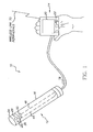
- FIG. 1 shows an intra-oral camera and display system according to the invention.
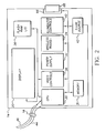
- FIG. 2 shows a block diagram of the electronics in the integral base.
- FIG. 3 shows the integral base for the light source and hand held monitor of the system shown in Figure 1, particularly as it would be used for wireless communication to a group of peripherals.
- FIG. 4 shows a flow chart for a process for correcting the color of the system shown in Figure 1.
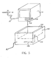
- FIG. 5 shows a second embodiment of an intra-oral camera and display system according to the invention.
- FIG. 6 shows a third embodiment of an intra-oral camera and display system according to the invention.
- an intra-oral dental camera system 10 includes a portable dental camera 12 and a power source, illumination source and a display unit integrally located in a portable enclosure (hereinafter referred to as the integral base 14) tethered to the camera 12.
- the camera 12 and the integral base 14 thus constitute, in the terms of this invention, an intra-oral camera with integral display.
- the dental camera 12 includes a handpiece 16 and a cable 18 connecting the dental camera 12 to the integral base 14.
- the integral base 14 can be easily cradled in a hand, and includes a display monitor 20 that can be easily hand positioned relative to the dentist's and/or patient's line of sight.
- a set of user controls 22 are provided on the integral base 14 that can be easily hand-navigated for controlling the illumination and the images displayed on the monitor, as well as communicating with peripheral devices.
- the handpiece 16 supports a removable lens unit 24 that includes a lens 26 and light emitting apertures 28.
- the handpiece 16 is generally elongated and cylindrical with a central axis.
- the lens 26 is positioned to receive light impinging on the handpiece in a direction substantially perpendicular and normal to the central axis of the handpiece.
- the integral base 14 further includes a central processing unit (CPU) 30, a CPU memory 31, a power supply 32, a wireless transceiver 34, and flash memory (RAM) 36.
- the user controls 22 interface with a video control unit 38 and an illuminator control unit 40.
- the illuminator control unit 40 connects with an illumination source 42, which provides illumination to the handpiece 16 through a fiber optic 44 that is part of the cable 18.
- the illumination source may take a variety of forms known to those of skill in this art, such as a halogen arc lamp lighting system or a tungsten/halogen lamp.
- the power supply 32 is connected by a power cable (not shown) to a power source, such as a wall socket.
- the image signal communication between the handpiece 16 and the CPU 30 is maintained through an electrical connection 46, which is also in the cable 18. While not shown in detail, the handpiece 16 also supports a connection of the fiber optic 44 with the light emitting apertures 28 and a connection of the electrical conductor 46 to an image sensor 50, such as a conventional charge coupled device (CCD).
- image sensor 50 is arranged in a conventional optical path, with mirrors and other optical components as might be necessary, such that the lens 26 can form an image of an intra-oral object on the image sensor 50.
- the high quality image display may be provided by a number of well-known technologies; for example, it is well-known in the art of hand-held televisions (e.g., the Casio EV660 Color Active Matrix Handheld TV) to use a small (e.g., 3 inch) screen with thin-film transistor active matrix (TFT) technology.
- hand-held televisions e.g., the Casio EV660 Color Active Matrix Handheld TV
- TFT thin-film transistor active matrix
- the means to accommodate a transfer of image data may include (a) wireless RF or microwave transceiver technology, (b) wireless infra-red transmission technology, and/or (c) removable memory technology embodied in physically small elements, such as flash RAM cards or small hard drives, that are easily removed from the camera part of the system and subsequently plugged into either the image data storage or printer parts of the system.
- the dental camera system 10 can, through the transceiver 34 in its integral base 14, initiate communication via wireless links 58 with a variety of peripheral units as shown in Figure 3.
- peripheral units include a larger monitor or television receiver 60, a printer 62, and a computer system 64, such as any conventional desktop PC, where the images may be stored.
- a dental practitioner may view an image on the integral base 14 and immediately initiate its transfer to any one of the peripheral units 60, 62 or 64 by means of the user controls 22.
- the incorporation of the transceiver 34 and the display monitor 20 into the dental camera system 10 further enables the practitioner to view the results of an image recording, and conveniently display the captured image(s) either for the practitioner's or patient's benefit.
- the transceiver 34 would receive images from a storage peripheral, such as the computer system 64, and display the stored images on the display monitor 20. Importantly, such viewing occurs without the requirement of producing a physical print of the image.
- the practitioner can separate the movable, but clumsy and sometimes bulky, printing and processing operation from the dental operatory, and devote a particular room to these peripherals.
- incorporation of the display as a tethered adjunct to the camera system removes the requirement on the dentist to move a large bulky system (a video monitor and/or attached computer) from one operating room to the next.
- the requirement that the dentist purchase multiple such systems for multiple operatories is eliminated.
- the image sensor 50 provides an image signal that the CPU 30 processes (as a video signal) for display on the display monitor 20.
- the video control unit 38 interacts through the CPU 30 and the user controls 22 to provide functionality for several modes, including a video/still mode, a mode for initiating a recording of a still or video sequence, a mode for stopping the imagery at any point (freeze-frame), a mode for initiating transmission to any of the peripherals shown in Figure 3 and a mode for initiating retrieval of a stored image from an external memory, e.g., from the computer system 64.
- the images are transmitted and/or received via an antenna or light beam emitter (not shown) to/from any of the peripherals 60, 62 or 64.
- the images may be stored in a removable memory and the removable memory is then transported to the peripheral units.
- the integral base 14 may also include a receptacle 66 for a physically small RAM card 68, which may be easily removed from the integral base 14 and subsequently plugged into a corresponding receptacle (not shown) in any one of the peripheral units 60, 62 and 64.
- Figure 4 shows the process for correcting the color of a system designed for the collection of intra-oral images. It is desirable to have a broadband match (broadband spectrum) because of the need to match teeth under a variety of illumination conditions.
- the camera is first initialized in a stage 70 to clear previous color correction factors from the CPU memory 31. These can be in the form of look up table elements, matrix elements, and the like.
- these digital data are used in a mathematical transformation process to modify the color characteristics of components of the system to allow for a true color rendition to occur throughout the system.
- the illuminator is allowed to stabilize for a period of time so that the spectral output of the illumination source 42 remains the same for a period of time that allows multiple images to be captured, without the need for adjustment of the illuminator color temperature (or spectral output characteristics).
- the display monitor 20 may also require a period of stabilization before use.
- target materials are illuminated with the illumination source 42 so as to characterize the image recording response.
- target materials can include, but are not limited to, color matching charts for the fabrication of color-matched prostheses.
- the target materials would include the white(s) that dental practitioners use to match teeth for prosthetic purposes, such as the fabrication of a crown. (Note that calibration would ordinarily not be done with the intra-oral camera in a patient's mouth; the camera would typically be hooked up to the computer 64 for this calibration process.) Calibration of the system includes measurements of such targets to establish the characteristic input color response for the intra-oral camera system.
- the characteristic is stored digitally in stage 74 in the CPU memory 31 and used to transform the unknown color of the teeth (which are imaged in a separate image recording event or events resulting from stage 76) to a color representation within the system that can be used to produce a "true-color" output.
- the calibration of each output device is also performed and stored in stage 78 in the respective memories (not shown) of each output device.
- the dental image is output to a selected output device(s) in stage 80, e.g., to the display monitor 20 or any of the output devices 60, 62 and 64 shown in Figure 3. In this manner, the system can correct for color imbalance in any of the components in the system and render color corrected output regardless of the output channel.
- the intra-oral camera and display system includes a docking unit 100 with a recessed area 102 for mating with the integral base 14.
- the power supply 32 in the integral base 14 includes rechargeable batteries 104 connected to externally accessible charging electrodes 106.
- the docking unit 100 is provided with a battery charger 108 connected to externally accessible charging electrodes 110.
- the handpiece 16 of the intra-oral camera and display system includes electronics and an interface for communicating with the integral base 14 across a wireless transmission linkage 116 or by means of a removable memory 118. More specifically, the handpiece 16 includes its own light source 120, processor 122, transceiver 124 and power supply 126.
- the power supply 126 may include rechargeable batteries 128, and the intra-oral camera and display system can further include a docking unit 130 with a battery charger 132. Both the handpiece 16 and the docking unit include mating electrodes 134 and 136 such that when the handpiece 16 is inserted into the docking unit 130, the electrodes 134 and 136 are electrically connected and the batteries 128 are recharged.
- the integral base may have its own docking unit; moreover, the two docking units could be combined in one component.
Landscapes
- Health & Medical Sciences (AREA)
- Life Sciences & Earth Sciences (AREA)
- Surgery (AREA)
- Engineering & Computer Science (AREA)
- Medical Informatics (AREA)
- General Health & Medical Sciences (AREA)
- Pathology (AREA)
- Radiology & Medical Imaging (AREA)
- Nuclear Medicine, Radiotherapy & Molecular Imaging (AREA)
- Biophysics (AREA)
- Biomedical Technology (AREA)
- Heart & Thoracic Surgery (AREA)
- Physics & Mathematics (AREA)
- Molecular Biology (AREA)
- Animal Behavior & Ethology (AREA)
- Optics & Photonics (AREA)
- Public Health (AREA)
- Veterinary Medicine (AREA)
- Computer Networks & Wireless Communication (AREA)
- Dentistry (AREA)
- Oral & Maxillofacial Surgery (AREA)
- Endoscopes (AREA)
- Dental Tools And Instruments Or Auxiliary Dental Instruments (AREA)
- Studio Devices (AREA)
- Instruments For Viewing The Inside Of Hollow Bodies (AREA)
- Transforming Light Signals Into Electric Signals (AREA)
- Closed-Circuit Television Systems (AREA)
Abstract
Description
- The present invention relates to intra-oral imaging systems for dental applications, and particularly to an intra-oral camera system that is used by a dental practitioner to display images of objects in the mouth.
- Electronic handheld cameras configured with intra-oral imaging optics are used for capturing images of the inside of a patient's mouth. The camera typically has an elongated body that contains an image sensor and optics. The optics and sensor are designed for capturing images of the inside of the mouth when the distal or viewing end of the camera is inserted into the patient's mouth. Wires carrying electronic signals typically connect the image sensor to the proximal end of the camera where a communication interface is provided to an image processing system or display monitor that allows manipulation and display of the images. By viewing the displayed images, a diagnosis can be made and appropriate treatment prescribed.
- For illuminating the inside of the mouth, a fiber optic cable typically is used to transmit light to the viewing end of the camera. The light is generated by a high intensity light source such as a lamp or bulb typically held in a light box. In a typical embodiment, such as shown in U.S. Patent No. 6,132,211, the fiber optic cable terminates in a connector that plugs into a power source housing that also includes the light source. Preferably, the housing for the power supply and the light source is supported on a countertop or on a post in the dental operatory room. In other words, the housing is basically immovable and portability is provided by having the portable handpiece removable from the housing. According to the '211 patent, this design is chosen so that any number of operatories having a power source base and display may be serviced by a single handpiece system.
- In a typical installation, the housing containing the power supply and the light box includes a communications interface to an external image processing system or display monitor. This leads to various placements of the processor and monitor. For instance, in the Reveal® Imaging Platform sold by Welch Allyn® the monitor is mounted on top of the housing, which makes the whole assembly virtually unmovable. Consequently, similar to what was described above in connection with the '211 patent, in the Reveal® Imaging Platform the handpiece is plugged into a receptacle on the housing.
- The use of intra-oral cameras among dental practitioners is well known. Besides their use in the diagnosis of dental and oral disease, they are used as well in providing a visual record of the condition of the patient. It is frequently the case that a dentist, orthodontist, or the like, may have multiple operatories where the use of such a camera is desirable. Current camera systems require either the use of an attached computer system and video monitor, or a separate monitor for the display of images. Thus the practitioner is required to either purchase multiple camera systems or display capabilities for each operatory, as such display systems are rather large and bulky.
- In many cases, a dentist desires to produce images of the interior of a patient's mouth in order to provide both a diagnosis of dental and oral disease as well as to provide a visual record of the condition of the patient. This process becomes cumbersome, costly, and inconvenient, as current camera systems are not designed for portability. What is needed is a truly portable camera system that would incorporate an integral display and provide advantages over the current state-of-the-art. Such a camera could incorporate wireless or other means to transmit the image data to a centrally located data storage and printing system.
- It is an object of the present invention to provide an intra-oral camera system with improved portability.
- It is a further object of the invention to provide an improved ability of the camera system to communicate with peripherals while preserving its portability.
- The present invention is directed to overcoming one or more of the problems set forth above. Briefly summarized, according to one aspect of the present invention, the invention resides in a portable intra-oral capture and display system comprising: (a) a handpiece elongated for insertion into an oral cavity, wherein the handpiece includes a light emitter on a distal end thereof for illuminating an object in the cavity and an image sensor for capturing an image of the object and generating an image signal therefrom; (b) a portable, hand-cradled base tethered to the handpiece, wherein the base contains in a single integral enclosure a light source for generating light, electronics for processing the image for display, a display monitor for displaying the image, a storage for storing the image, thereby providing a stored image for subsequent review and access, and an interface for transferring the stored image to a peripheral device; and (c) an optical connection for transmitting the light from the base to the light emitter in the camera, and an electrical connection for communicating the image signal from the image sensor in the camera to the processor in the base.
- In a further aspect of the invention, the capture and display system includes both a high quality image display along with means to transfer image data to a physically separate and distinct data storage in a peripheral device, such as a larger monitor, a printer or a computer. The means to transfer image data may comprise, for example: (a) wireless RF or microwave transceiver technology, (b) wireless IR technology, or (c) a physically small memory device, such as a flash RAM card, that is easily removed from the camera part of the system and subsequently plugged into the peripheral device.
- The advantage of the present invention lies in the integration of the display into the camera system. This integration enables the practitioner to view the results of image recording in close proximity to the capture location, and conveniently display the captured image(s) either for the practitioner's or patient's benefit. Such viewing occurs without the requirement of producing a physical print of the image. Integration of the display removes the requirement on the dentist to move a large bulky system (a video monitor and/or attached computer) from one operating room to the next. Alternatively, the requirement that the dentist purchase multiple such systems is eliminated.
- These and other aspects, objects, features and advantages of the present invention will be more clearly understood and appreciated from a review of the following detailed description of the preferred embodiments and appended claims, and by reference to the accompanying drawings.
- FIG. 1 shows an intra-oral camera and display system according to the invention.
- FIG. 2 shows a block diagram of the electronics in the integral base.
- FIG. 3 shows the integral base for the light source and hand held monitor of the system shown in Figure 1, particularly as it would be used for wireless communication to a group of peripherals.
- FIG. 4 shows a flow chart for a process for correcting the color of the system shown in Figure 1.
- FIG. 5 shows a second embodiment of an intra-oral camera and display system according to the invention.
- FIG. 6 shows a third embodiment of an intra-oral camera and display system according to the invention.
- Because intra-oral cameras employing electronic sensors are well known, the present description will be directed in particular to elements forming part of, or cooperating more directly with, apparatus in accordance with the present invention. Elements not specifically shown or described herein may be selected from those known in the art. Certain aspects of the embodiments to be described may be provided in software. Given the system as shown and described according to the invention in the following materials, software not specifically shown, described or suggested herein that is useful for implementation of the invention is conventional and within the ordinary skill in such arts.
- Referring first to Figure 1, an intra-oral
dental camera system 10 includes a portabledental camera 12 and a power source, illumination source and a display unit integrally located in a portable enclosure (hereinafter referred to as the integral base 14) tethered to thecamera 12. Thecamera 12 and theintegral base 14 thus constitute, in the terms of this invention, an intra-oral camera with integral display. Thedental camera 12 includes ahandpiece 16 and acable 18 connecting thedental camera 12 to theintegral base 14. As shown for illustrative purposes in Figure 1, theintegral base 14 can be easily cradled in a hand, and includes adisplay monitor 20 that can be easily hand positioned relative to the dentist's and/or patient's line of sight. A set ofuser controls 22 are provided on theintegral base 14 that can be easily hand-navigated for controlling the illumination and the images displayed on the monitor, as well as communicating with peripheral devices. Thehandpiece 16 supports aremovable lens unit 24 that includes alens 26 andlight emitting apertures 28. Thehandpiece 16 is generally elongated and cylindrical with a central axis. Thelens 26 is positioned to receive light impinging on the handpiece in a direction substantially perpendicular and normal to the central axis of the handpiece. - Referring to Figure 2, the
integral base 14 further includes a central processing unit (CPU) 30, aCPU memory 31, apower supply 32, awireless transceiver 34, and flash memory (RAM) 36. The user controls 22 interface with avideo control unit 38 and anilluminator control unit 40. Theilluminator control unit 40 connects with anillumination source 42, which provides illumination to thehandpiece 16 through a fiber optic 44 that is part of thecable 18. The illumination source may take a variety of forms known to those of skill in this art, such as a halogen arc lamp lighting system or a tungsten/halogen lamp. Thepower supply 32 is connected by a power cable (not shown) to a power source, such as a wall socket. The image signal communication between thehandpiece 16 and theCPU 30 is maintained through anelectrical connection 46, which is also in thecable 18. While not shown in detail, thehandpiece 16 also supports a connection of thefiber optic 44 with thelight emitting apertures 28 and a connection of theelectrical conductor 46 to animage sensor 50, such as a conventional charge coupled device (CCD). Theimage sensor 50 is arranged in a conventional optical path, with mirrors and other optical components as might be necessary, such that thelens 26 can form an image of an intra-oral object on theimage sensor 50. - It should be noted that portability is facilitated by incorporating into the
dental camera system 10 both a highquality image display 20 along with means to transfer image data to a physically separate and distinct data storage associated with an image printing capability. The high quality image display may be provided by a number of well-known technologies; for example, it is well-known in the art of hand-held televisions (e.g., the Casio EV660 Color Active Matrix Handheld TV) to use a small (e.g., 3 inch) screen with thin-film transistor active matrix (TFT) technology. The means to accommodate a transfer of image data may include (a) wireless RF or microwave transceiver technology, (b) wireless infra-red transmission technology, and/or (c) removable memory technology embodied in physically small elements, such as flash RAM cards or small hard drives, that are easily removed from the camera part of the system and subsequently plugged into either the image data storage or printer parts of the system. - Accordingly, the
dental camera system 10 can, through thetransceiver 34 in itsintegral base 14, initiate communication via wireless links 58 with a variety of peripheral units as shown in Figure 3. Each of these units would have its own data storage for receiving the transmitted images. Without intending to be exhaustive as to type of peripheral unit that may be accessed, such peripheral units include a larger monitor ortelevision receiver 60, aprinter 62, and acomputer system 64, such as any conventional desktop PC, where the images may be stored. With this arrangement, a dental practitioner may view an image on theintegral base 14 and immediately initiate its transfer to any one of theperipheral units transceiver 34 and the display monitor 20 into thedental camera system 10 further enables the practitioner to view the results of an image recording, and conveniently display the captured image(s) either for the practitioner's or patient's benefit. For this purpose, thetransceiver 34 would receive images from a storage peripheral, such as thecomputer system 64, and display the stored images on thedisplay monitor 20. Importantly, such viewing occurs without the requirement of producing a physical print of the image. - Just as importantly, with this arrangement the practitioner can separate the movable, but clumsy and sometimes bulky, printing and processing operation from the dental operatory, and devote a particular room to these peripherals. Moreover, incorporation of the display as a tethered adjunct to the camera system removes the requirement on the dentist to move a large bulky system (a video monitor and/or attached computer) from one operating room to the next. Alternatively, the requirement that the dentist purchase multiple such systems for multiple operatories is eliminated.
- In a preferred embodiment, the
image sensor 50 provides an image signal that theCPU 30 processes (as a video signal) for display on thedisplay monitor 20. Thevideo control unit 38 interacts through theCPU 30 and the user controls 22 to provide functionality for several modes, including a video/still mode, a mode for initiating a recording of a still or video sequence, a mode for stopping the imagery at any point (freeze-frame), a mode for initiating transmission to any of the peripherals shown in Figure 3 and a mode for initiating retrieval of a stored image from an external memory, e.g., from thecomputer system 64. In the latter two modes, the images are transmitted and/or received via an antenna or light beam emitter (not shown) to/from any of theperipherals integral base 14 may also include areceptacle 66 for a physicallysmall RAM card 68, which may be easily removed from theintegral base 14 and subsequently plugged into a corresponding receptacle (not shown) in any one of theperipheral units - In order to adjust the colorimetry of the
dental camera system 10 to match the color of intra-oral objects, e.g., to match a natural tooth color, it is desirable to provide an optimum color calibration for an intra-oral camera application. Figure 4 shows the process for correcting the color of a system designed for the collection of intra-oral images. It is desirable to have a broadband match (broadband spectrum) because of the need to match teeth under a variety of illumination conditions. The camera is first initialized in astage 70 to clear previous color correction factors from theCPU memory 31. These can be in the form of look up table elements, matrix elements, and the like. As is well-known in the color management arts, these digital data are used in a mathematical transformation process to modify the color characteristics of components of the system to allow for a true color rendition to occur throughout the system. The illuminator is allowed to stabilize for a period of time so that the spectral output of theillumination source 42 remains the same for a period of time that allows multiple images to be captured, without the need for adjustment of the illuminator color temperature (or spectral output characteristics). The display monitor 20 may also require a period of stabilization before use. - In
stage 72, target materials are illuminated with theillumination source 42 so as to characterize the image recording response. Such target materials can include, but are not limited to, color matching charts for the fabrication of color-matched prostheses. For example, the target materials would include the white(s) that dental practitioners use to match teeth for prosthetic purposes, such as the fabrication of a crown. (Note that calibration would ordinarily not be done with the intra-oral camera in a patient's mouth; the camera would typically be hooked up to thecomputer 64 for this calibration process.) Calibration of the system includes measurements of such targets to establish the characteristic input color response for the intra-oral camera system. The characteristic is stored digitally instage 74 in theCPU memory 31 and used to transform the unknown color of the teeth (which are imaged in a separate image recording event or events resulting from stage 76) to a color representation within the system that can be used to produce a "true-color" output. The calibration of each output device is also performed and stored instage 78 in the respective memories (not shown) of each output device. Then, the dental image is output to a selected output device(s) instage 80, e.g., to the display monitor 20 or any of theoutput devices - In a second embodiment of the invention shown in Figure 5, the intra-oral camera and display system includes a docking unit 100 with a recessed
area 102 for mating with theintegral base 14. Thepower supply 32 in theintegral base 14 includesrechargeable batteries 104 connected to externally accessible charging electrodes 106. The docking unit 100 is provided with abattery charger 108 connected to externallyaccessible charging electrodes 110. When theintegral base 14 is inserted into the recessedarea 102 on the docking unit 100, theelectrodes 106 and 110 are electrically connected and thebatteries 104 are recharged. - In a third embodiment of the invention shown in Figure 6, the
handpiece 16 of the intra-oral camera and display system includes electronics and an interface for communicating with theintegral base 14 across awireless transmission linkage 116 or by means of aremovable memory 118. More specifically, thehandpiece 16 includes its ownlight source 120,processor 122,transceiver 124 andpower supply 126. In addition, thepower supply 126 may includerechargeable batteries 128, and the intra-oral camera and display system can further include adocking unit 130 with abattery charger 132. Both thehandpiece 16 and the docking unit includemating electrodes handpiece 16 is inserted into thedocking unit 130, theelectrodes batteries 128 are recharged. In addition, as shown in Figure 5, the integral base may have its own docking unit; moreover, the two docking units could be combined in one component.
Claims (18)
- A portable intra-oral capture and display system, said system comprising:a handpiece elongated for insertion into an oral cavity, said handpiece including a light emitter on a distal end thereof for illuminating an object in the cavity and an image sensor for capturing an image of the object and generating an image signal therefrom;a portable, hand-cradled base tethered to the handpiece, said base containing in a single integral enclosure a light source for generating light, electronics for processing the image for display, a display monitor for displaying the image, a storage for storing the image, thereby providing a stored image for subsequent review and access, and an interface for transferring the stored image to a peripheral device; andan optical connection for transmitting the light from the base to the light emitter in the camera, and an electrical connection for communicating the image signal from the image sensor in the camera to the electronics in the base.
- The intra-oral capture and display system as claimed in claim 1 wherein the optical and electrical connections are bundled in a single cable that tethers the base to the handpiece.
- The intra-oral capture and display system as claimed in claim 1 wherein the image displayed is a motion image.
- The intra-oral capture and display system as claimed in claim 1 wherein the image displayed is a still image.
- The intra-oral capture and display system as claimed in claim 1 wherein the electronics includes user controls for manipulating the image on the display.
- The intra-oral capture and display system as claimed in claim 1 wherein the electronics allows the user to initiate transfer of the image to the peripheral device across the interface.
- The intra-oral capture and display system as claimed in claim 1 wherein the electronics allows the user to retrieve an image from the peripheral device across the interface.
- The intra-oral capture and display system as claimed in claim 1 wherein the storage is a flash RAM.
- The intra-oral capture and display system as claimed in claim 1 wherein the interface includes an electrical receptacle connected to the electronics for receiving a removable storage device on which the image may be stored.
- The intra-oral capture and display system as claimed in claim 1 wherein the interface includes a transceiver for initiating a wireless connection with the peripheral.
- The intra-oral capture and display system as claimed in claim 1 wherein the peripheral includes at least one of a printer, a monitor and a computer.
- A portable intra-oral capture and display system, said system comprising:a handpiece elongated for insertion into an oral cavity, said handpiece including a light emitter on a distal end thereof for illuminating an object in the cavity and an image sensor for capturing an image of the object and generating an image signal therefrom;a portable, hand-cradled base tethered to the handpiece, said base containing in a single integral enclosure a light source for generating light, electronics for processing the image for display, a display monitor for displaying the image, and a power supply including rechargeable batteries for powering the base;a docking unit for receiving the base, said docking unit having a battery recharger for recharging the batteries in the base when the base is received into the docking unit; andan optical connection for transmitting the light from the base to the light emitter in the camera, and an electrical connection for communicating the image signal from the image sensor in the camera to the electronics in the base.
- A portable intra-oral capture and display system, said system comprising:a handpiece elongated for insertion into an oral cavity, said handpiece including a light emitter on a distal end thereof for illuminating an object in the cavity and an image sensor for capturing an image of the object and generating an image signal therefrom, said handpiece including a light source for generating light for the light emitter, electronics for processing the image signal, an interface for transferring the image signal from the handpiece and a power supply for powering the handpiece; anda portable, hand-cradled base containing in a single integral enclosure an interface for receiving the image signal from the handpiece, electronics for processing the image signal for display, a display monitor for displaying the image signal, and a power supply for powering the base.
- The intra-oral capture and display system as claimed in claim 13 wherein the interface includes a removable storage device on which the image may be stored.
- The intra-oral capture and display system as claimed in claim 13 wherein the interface includes a transceiver for initiating a wireless connection with the base.
- The intra-oral capture and display system as claimed in claim 13 wherein the power supply in the handpiece further includes a rechargeable battery and the system further includes a docking unit for receiving the handpiece, said docking unit having a battery recharger for recharging the batteries in the handpiece when the handpiece is received into the docking unit.
- The intra-oral capture and display system as claimed in claim 13 wherein the power supply in the base further includes a rechargeable battery and the system further includes a docking unit for receiving the base, said docking unit having a battery recharger for recharging the batteries in the base when the base is received into the docking unit.
- The intra-oral capture and display system as claimed in claim 13 wherein the power supplies in the handpiece and base includes respective rechargeable batteries, and the system further includes a docking unit for receiving both the handpiece and the base, said docking unit having a battery recharger for recharging the batteries in the handpiece and base when the handpiece and base are received into the docking unit.
Applications Claiming Priority (2)
| Application Number | Priority Date | Filing Date | Title |
|---|---|---|---|
| US09/796,239 US7057639B2 (en) | 2001-02-28 | 2001-02-28 | Intra-oral camera with integral display |
| US796239 | 2001-02-28 |
Publications (3)
| Publication Number | Publication Date |
|---|---|
| EP1238624A2 true EP1238624A2 (en) | 2002-09-11 |
| EP1238624A3 EP1238624A3 (en) | 2003-12-10 |
| EP1238624B1 EP1238624B1 (en) | 2006-04-26 |
Family
ID=25167685
Family Applications (1)
| Application Number | Title | Priority Date | Filing Date |
|---|---|---|---|
| EP02075645A Expired - Lifetime EP1238624B1 (en) | 2001-02-28 | 2002-02-18 | Intra-oral camera with integral display |
Country Status (4)
| Country | Link |
|---|---|
| US (2) | US7057639B2 (en) |
| EP (1) | EP1238624B1 (en) |
| JP (1) | JP4240892B2 (en) |
| DE (1) | DE60210850T2 (en) |
Cited By (4)
| Publication number | Priority date | Publication date | Assignee | Title |
|---|---|---|---|---|
| WO2004112638A1 (en) * | 2003-06-21 | 2004-12-29 | Hideyo Uji | Hand piece for dental cutting with video camera and visualizer |
| WO2005039402A1 (en) * | 2003-10-06 | 2005-05-06 | Eastman Kodak Company | Diagnostic alignment of in vivo images |
| WO2011029530A1 (en) * | 2009-09-14 | 2011-03-17 | DüRR DENTAL AG | Handpiece camera |
| WO2016162552A1 (en) * | 2015-04-09 | 2016-10-13 | Sirona Dental Systems Gmbh | Method and measurement system for optically measuring an object |
Families Citing this family (71)
| Publication number | Priority date | Publication date | Assignee | Title |
|---|---|---|---|---|
| US7728845B2 (en) * | 1996-02-26 | 2010-06-01 | Rah Color Technologies Llc | Color calibration of color image rendering devices |
| WO1999010866A1 (en) * | 1997-08-25 | 1999-03-04 | Imagicolor Corp | A system for distributing and controlling color reproduction at multiple sites |
| US7139016B2 (en) * | 2001-02-28 | 2006-11-21 | Eastman Kodak Company | Intra-oral camera system with chair-mounted display |
| US8038602B2 (en) * | 2001-10-19 | 2011-10-18 | Visionscope Llc | Portable imaging system employing a miniature endoscope |
| US20070167681A1 (en) | 2001-10-19 | 2007-07-19 | Gill Thomas J | Portable imaging system employing a miniature endoscope |
| US10595710B2 (en) | 2001-10-19 | 2020-03-24 | Visionscope Technologies Llc | Portable imaging system employing a miniature endoscope |
| US7129986B2 (en) * | 2002-01-23 | 2006-10-31 | Guan-Wu Wang | Wireless camera system |
| AU2003274984A1 (en) * | 2002-09-13 | 2004-04-30 | Karl Storz Imaging, Inc. | Video recording and image capture device |
| US20040056961A1 (en) * | 2002-09-24 | 2004-03-25 | Kenzo Ito | Single-hand held camera usable in narrow space |
| EP1551277B1 (en) * | 2002-10-03 | 2007-08-08 | Etview Ltd. | Endotracheal tube with an imaging sensor |
| JP4475923B2 (en) * | 2003-01-14 | 2010-06-09 | 株式会社モリタ製作所 | Diagnostic camera |
| DE102004001856B4 (en) | 2003-01-14 | 2019-05-23 | J. Morita Mfg. Corp. | Imaging device for diagnostic purposes |
| JP4521180B2 (en) * | 2003-12-05 | 2010-08-11 | 株式会社モリタ製作所 | Diagnostic camera |
| US20040252188A1 (en) * | 2003-03-21 | 2004-12-16 | Stantchev Gueorgui H. | Methods and apparatus for imaging |
| JP2004321344A (en) * | 2003-04-23 | 2004-11-18 | Pentax Corp | Monitor integrated processor for electronic endoscope |
| US7245753B2 (en) | 2003-06-26 | 2007-07-17 | Carestream Health, Inc. | Method for determining dental alignment using radiographs |
| KR100539934B1 (en) * | 2003-07-16 | 2005-12-28 | 삼성전자주식회사 | Portable communication apparatus |
| US7713058B2 (en) * | 2003-07-28 | 2010-05-11 | Atsushi Takahashi | Dental mirror, and an intraoral camera system using the same |
| JP2005080752A (en) * | 2003-09-05 | 2005-03-31 | Pentax Corp | Endoscope system |
| US20050196039A1 (en) * | 2004-03-02 | 2005-09-08 | Wolfgang Bengel | Method for color determination using a digital camera |
| US8725525B2 (en) * | 2004-04-13 | 2014-05-13 | Olympus Corporation | Endoscope system |
| EP1937179A2 (en) * | 2005-05-03 | 2008-07-02 | Randall W. Donahoo | Camera system |
| JP4813898B2 (en) * | 2005-12-26 | 2011-11-09 | 株式会社カナガワファニチュア | Digital camera for intraoral photography |
| US20100145146A1 (en) * | 2005-12-28 | 2010-06-10 | Envisionier Medical Technologies, Inc. | Endoscopic digital recording system with removable screen and storage device |
| US8194132B2 (en) | 2006-01-20 | 2012-06-05 | Old World Industries, Llc | System for monitoring an area adjacent a vehicle |
| CN101484066B (en) * | 2006-07-25 | 2012-01-04 | 宝洁公司 | Methods and products for analyzing gingival tissue |
| US8360771B2 (en) * | 2006-12-28 | 2013-01-29 | Therametric Technologies, Inc. | Handpiece for detection of dental demineralization |
| JP5145587B2 (en) * | 2007-12-27 | 2013-02-20 | 晃一 角田 | Oral insert and oropharyngeal mirror device |
| CA2717776C (en) | 2008-03-07 | 2018-05-22 | Milwaukee Electric Tool Corporation | Visual inspection device |
| EP2276392A4 (en) * | 2008-04-14 | 2013-03-27 | Univ Carnegie Mellon | ARTICULATED DEVICE WITH VISUALIZATION SYSTEM |
| US9095298B2 (en) * | 2008-06-23 | 2015-08-04 | Intubrite, Llc | Adjustable display mechanism and method |
| CL2008003661A1 (en) * | 2008-12-10 | 2010-12-10 | Aplik S A | Method and device for quantitatively determining the surface optical characteristics of a reference object composed of a plurality of optically differentiable layers. |
| US20100275122A1 (en) * | 2009-04-27 | 2010-10-28 | Microsoft Corporation | Click-through controller for mobile interaction |
| FR2965369B1 (en) * | 2010-09-29 | 2013-04-12 | Tokendo | VIDEOENDOSCOPE WITH CONFIGURABLE TOUCH COMMANDS |
| US20120178991A1 (en) * | 2011-01-10 | 2012-07-12 | QuickLook, Inc. | Camera, camera system, and methods of using the same |
| AU2012206109B2 (en) | 2011-01-11 | 2015-02-19 | Kabushiki Kaisya Advance | Oral imaging and display system |
| TWM411744U (en) * | 2011-04-12 | 2011-09-11 | Digilife Technologies Co Ltd | Wireless image-capturing device |
| JP5875258B2 (en) * | 2011-06-20 | 2016-03-02 | キヤノン株式会社 | Imaging device |
| PL2611356T3 (en) | 2011-07-11 | 2015-08-31 | Etview Ltd | Endobronchial tube |
| US20130183633A1 (en) * | 2012-01-13 | 2013-07-18 | Ormco Corporation | System and method for three-dimensional intra-oral imaging |
| US8712228B2 (en) * | 2012-02-07 | 2014-04-29 | Carestream Health, Inc. | Intraoral camera for dental chairs |
| EP2868096B1 (en) * | 2012-06-27 | 2020-08-05 | Zipline Health, Inc. | Devices, methods and systems for acquiring medical diagnostic information and provision of telehealth services |
| US9060674B2 (en) | 2012-10-11 | 2015-06-23 | Karl Storz Imaging, Inc. | Auto zoom for video camera |
| EP2754384B1 (en) | 2013-01-10 | 2018-07-11 | Ambu A/S | Endobronchial tube with integrated image sensor and cleaning nozzle arrangement |
| CN103142204A (en) * | 2013-01-23 | 2013-06-12 | 杭州好克光电仪器有限公司 | Electronic endoscope |
| US9017069B2 (en) * | 2013-05-13 | 2015-04-28 | Elwha Llc | Oral illumination systems and methods |
| DE102013106556A1 (en) * | 2013-06-24 | 2014-12-24 | Qioptiq Photonics Gmbh & Co. Kg | Method of operating a dental camera |
| CN103784106A (en) * | 2014-02-17 | 2014-05-14 | 深圳市古安泰自动化技术有限公司 | Wireless body surface checking device |
| US9842551B2 (en) | 2014-06-10 | 2017-12-12 | Apple Inc. | Display driver circuitry with balanced stress |
| CN104127164B (en) * | 2014-07-24 | 2015-10-21 | 电子科技大学 | A kind of portable intelligent medical endoscope |
| US10178946B2 (en) * | 2014-09-08 | 2019-01-15 | Location Labs, Inc. | Oral monitor |
| CN104323757A (en) * | 2014-11-13 | 2015-02-04 | 王卫东 | Endoscope with flash lamp and camera for portable intelligent equipment |
| EP3220848B1 (en) * | 2014-11-20 | 2021-01-13 | Stayclear Dental Mirror, LLC | Multi-purpose dental instrument |
| US10074178B2 (en) * | 2015-01-30 | 2018-09-11 | Dental Imaging Technologies Corporation | Intra-oral image acquisition alignment |
| WO2016137838A1 (en) * | 2015-02-23 | 2016-09-01 | Xiaolong Ouyang | Handheld surgical endoscope |
| US10869592B2 (en) | 2015-02-23 | 2020-12-22 | Uroviu Corp. | Handheld surgical endoscope |
| US11558538B2 (en) | 2016-03-18 | 2023-01-17 | Opkix, Inc. | Portable camera system |
| DE102016111960A1 (en) * | 2016-06-30 | 2018-01-04 | Karl Storz Gmbh & Co. Kg | Device for videoendoscopy |
| US11832797B2 (en) | 2016-09-25 | 2023-12-05 | Micronvision Corp. | Endoscopic fluorescence imaging |
| US11684248B2 (en) | 2017-09-25 | 2023-06-27 | Micronvision Corp. | Endoscopy/stereo colposcopy medical instrument |
| US20180249094A1 (en) * | 2017-02-27 | 2018-08-30 | Opkix, Inc | Wireless Camera System |
| US10376149B2 (en) | 2017-07-11 | 2019-08-13 | Colgate-Palmolive Company | Oral care evaluation system and process |
| US11980342B2 (en) | 2020-11-12 | 2024-05-14 | Micronvision Corp. | Minimally invasive endoscope |
| US12268358B2 (en) | 2019-12-05 | 2025-04-08 | Uroviu Corp. | Portable endoscope with side-mountable disposable portion |
| US11771304B1 (en) | 2020-11-12 | 2023-10-03 | Micronvision Corp. | Minimally invasive endoscope |
| WO2020102237A1 (en) | 2018-11-13 | 2020-05-22 | Opkix, Inc. | Wearable mounts for portable camera |
| HU5078U (en) * | 2019-05-10 | 2019-10-28 | Dental Scanner Solutions Kft | Dental scanner device |
| WO2021016626A1 (en) | 2019-07-25 | 2021-01-28 | Uroviu Corp. | Disposable endoscopy cannula with integrated grasper |
| US11426055B2 (en) * | 2020-02-21 | 2022-08-30 | Ambu A/S | Medical visualisation system including a monitor and a graphical user interface therefore |
| US11382727B1 (en) | 2021-05-19 | 2022-07-12 | Thamer Marghalani | Three-dimensional oral imaging system and method |
| US12257114B1 (en) | 2023-04-03 | 2025-03-25 | Forte Creates, LLC | Vacuum light apparatus |
Citations (1)
| Publication number | Priority date | Publication date | Assignee | Title |
|---|---|---|---|---|
| US6132211A (en) | 1993-10-08 | 2000-10-17 | Dentsply International Inc. | Portable dental camera, system and method |
Family Cites Families (20)
| Publication number | Priority date | Publication date | Assignee | Title |
|---|---|---|---|---|
| US4742819A (en) | 1987-03-23 | 1988-05-10 | George Gordon P | Intubating scope with camera and screen |
| US5134469A (en) | 1989-11-16 | 1992-07-28 | Olympus Optical Co., Ltd. | Endoscope light source apparatus with detachable flash unit |
| US5363838B1 (en) | 1992-12-09 | 2000-03-28 | Gordon P George | Fiberoptic intubating scope with camera and lightweight portable screen and method of using same |
| WO1994023375A1 (en) * | 1993-03-31 | 1994-10-13 | Luma Corporation | Managing information in an endoscopy system |
| US5527261A (en) * | 1994-08-18 | 1996-06-18 | Welch Allyn, Inc. | Remote hand-held diagnostic instrument with video imaging |
| US5882206A (en) * | 1995-03-29 | 1999-03-16 | Gillio; Robert G. | Virtual surgery system |
| US5766006A (en) | 1995-06-26 | 1998-06-16 | Murljacic; Maryann Lehmann | Tooth shade analyzer system and methods |
| US5880826A (en) * | 1997-07-01 | 1999-03-09 | L J Laboratories, L.L.C. | Apparatus and method for measuring optical characteristics of teeth |
| US5820606A (en) * | 1996-06-11 | 1998-10-13 | Origin Medsystems, Inc. | Reusable cannula with disposable seal |
| US6554765B1 (en) * | 1996-07-15 | 2003-04-29 | East Giant Limited | Hand held, portable camera with adaptable lens system |
| US5827178A (en) | 1997-01-02 | 1998-10-27 | Berall; Jonathan | Laryngoscope for use in trachea intubation |
| US6106457A (en) | 1997-04-04 | 2000-08-22 | Welch Allyn, Inc. | Compact imaging instrument system |
| US6452626B1 (en) * | 1997-10-06 | 2002-09-17 | Edwin L. Adair | Communication devices incorporating reduced area imaging devices |
| US6982742B2 (en) | 1997-10-06 | 2006-01-03 | Adair Edwin L | Hand-held computers incorporating reduced area imaging devices |
| JPH11192207A (en) | 1997-11-07 | 1999-07-21 | Matsushita Electric Ind Co Ltd | Videoscope and mobile storage case |
| US6123437A (en) * | 1998-06-03 | 2000-09-26 | Integra Medical | Easy access light box |
| EP0992843A3 (en) | 1998-10-09 | 2000-07-19 | Nix Company Ltd. | Film image display system |
| US6224542B1 (en) * | 1999-01-04 | 2001-05-01 | Stryker Corporation | Endoscopic camera system with non-mechanical zoom |
| US20020067407A1 (en) | 2000-04-06 | 2002-06-06 | Cooper David H. | Universal docking station for imaging systems in a dental operatory |
| US6761561B2 (en) | 2002-06-07 | 2004-07-13 | Schick Technologies | Wireless dental camera |
-
2001
- 2001-02-28 US US09/796,239 patent/US7057639B2/en not_active Expired - Lifetime
-
2002
- 2002-02-18 DE DE60210850T patent/DE60210850T2/en not_active Expired - Lifetime
- 2002-02-18 EP EP02075645A patent/EP1238624B1/en not_active Expired - Lifetime
- 2002-02-28 JP JP2002055088A patent/JP4240892B2/en not_active Expired - Fee Related
- 2002-09-10 US US10/238,174 patent/US6956601B2/en not_active Expired - Lifetime
Patent Citations (1)
| Publication number | Priority date | Publication date | Assignee | Title |
|---|---|---|---|---|
| US6132211A (en) | 1993-10-08 | 2000-10-17 | Dentsply International Inc. | Portable dental camera, system and method |
Cited By (8)
| Publication number | Priority date | Publication date | Assignee | Title |
|---|---|---|---|---|
| WO2004112638A1 (en) * | 2003-06-21 | 2004-12-29 | Hideyo Uji | Hand piece for dental cutting with video camera and visualizer |
| WO2005039402A1 (en) * | 2003-10-06 | 2005-05-06 | Eastman Kodak Company | Diagnostic alignment of in vivo images |
| US7319781B2 (en) | 2003-10-06 | 2008-01-15 | Carestream Health, Inc. | Method and system for multiple passes diagnostic alignment for in vivo images |
| WO2011029530A1 (en) * | 2009-09-14 | 2011-03-17 | DüRR DENTAL AG | Handpiece camera |
| DE102009041151B4 (en) | 2009-09-14 | 2019-06-13 | Dürr Dental SE | Handpiece camera |
| EA035239B1 (en) * | 2009-09-14 | 2020-05-20 | Дюрр Денталь Аг | Intraoral camera |
| WO2016162552A1 (en) * | 2015-04-09 | 2016-10-13 | Sirona Dental Systems Gmbh | Method and measurement system for optically measuring an object |
| US10390693B2 (en) | 2015-04-09 | 2019-08-27 | Dentsply Sirona Inc. | Method and measurement system for optically measuring an object |
Also Published As
| Publication number | Publication date |
|---|---|
| JP4240892B2 (en) | 2009-03-18 |
| US6956601B2 (en) | 2005-10-18 |
| DE60210850D1 (en) | 2006-06-01 |
| US20030016284A1 (en) | 2003-01-23 |
| US20020118279A1 (en) | 2002-08-29 |
| JP2002355262A (en) | 2002-12-10 |
| EP1238624B1 (en) | 2006-04-26 |
| DE60210850T2 (en) | 2006-11-23 |
| US7057639B2 (en) | 2006-06-06 |
| EP1238624A3 (en) | 2003-12-10 |
Similar Documents
| Publication | Publication Date | Title |
|---|---|---|
| EP1238624B1 (en) | Intra-oral camera with integral display | |
| US7139016B2 (en) | Intra-oral camera system with chair-mounted display | |
| US6908307B2 (en) | Dental camera utilizing multiple lenses | |
| US6626825B2 (en) | Medical inspection device | |
| US6186944B1 (en) | Medical inspection device | |
| US6361489B1 (en) | Medical inspection device | |
| US7137948B2 (en) | Medical inspection device | |
| US5311859A (en) | Add-on video camera arrangement for optical laparoscope | |
| US7419467B2 (en) | Medical inspection device | |
| US4639772A (en) | Focusable video camera for use with endoscopes | |
| WO2003103528A2 (en) | Wireless dental camera | |
| EP0941691A1 (en) | Compact video imaging assembly | |
| US20060161048A1 (en) | Flexible video scope extension and methods | |
| US20030107652A1 (en) | Dental video camera | |
| US20020135694A1 (en) | Dental video camera | |
| JPH119548A (en) | Portable electronic endoscope | |
| JP4503734B2 (en) | Electronic endoscope | |
| US6404984B1 (en) | Lighted camera for dental examinations and method of using the same | |
| US20040252188A1 (en) | Methods and apparatus for imaging | |
| AU2002250553B2 (en) | Dental video imaging system | |
| US4600938A (en) | Focusable video camera for use with endoscopes | |
| AU2002250553A1 (en) | Dental video imaging system | |
| JPH08117184A (en) | Endoscope device | |
| EP0813795A1 (en) | Imaging device | |
| KR20000053868A (en) | vision system for diagnosis |
Legal Events
| Date | Code | Title | Description |
|---|---|---|---|
| PUAI | Public reference made under article 153(3) epc to a published international application that has entered the european phase |
Free format text: ORIGINAL CODE: 0009012 |
|
| AK | Designated contracting states |
Kind code of ref document: A2 Designated state(s): AT BE CH CY DE DK ES FI FR GB GR IE IT LI LU MC NL PT SE TR |
|
| AX | Request for extension of the european patent |
Free format text: AL;LT;LV;MK;RO;SI |
|
| PUAL | Search report despatched |
Free format text: ORIGINAL CODE: 0009013 |
|
| AK | Designated contracting states |
Kind code of ref document: A3 Designated state(s): AT BE CH CY DE DK ES FI FR GB GR IE IT LI LU MC NL PT SE TR |
|
| AX | Request for extension of the european patent |
Extension state: AL LT LV MK RO SI |
|
| 17P | Request for examination filed |
Effective date: 20040518 |
|
| 17Q | First examination report despatched |
Effective date: 20040618 |
|
| AKX | Designation fees paid |
Designated state(s): DE FR GB |
|
| GRAP | Despatch of communication of intention to grant a patent |
Free format text: ORIGINAL CODE: EPIDOSNIGR1 |
|
| GRAS | Grant fee paid |
Free format text: ORIGINAL CODE: EPIDOSNIGR3 |
|
| GRAA | (expected) grant |
Free format text: ORIGINAL CODE: 0009210 |
|
| AK | Designated contracting states |
Kind code of ref document: B1 Designated state(s): DE FR GB |
|
| REG | Reference to a national code |
Ref country code: GB Ref legal event code: FG4D |
|
| REF | Corresponds to: |
Ref document number: 60210850 Country of ref document: DE Date of ref document: 20060601 Kind code of ref document: P |
|
| ET | Fr: translation filed | ||
| PLBE | No opposition filed within time limit |
Free format text: ORIGINAL CODE: 0009261 |
|
| STAA | Information on the status of an ep patent application or granted ep patent |
Free format text: STATUS: NO OPPOSITION FILED WITHIN TIME LIMIT |
|
| 26N | No opposition filed |
Effective date: 20070129 |
|
| REG | Reference to a national code |
Ref country code: GB Ref legal event code: 732E |
|
| REG | Reference to a national code |
Ref country code: FR Ref legal event code: TP |
|
| REG | Reference to a national code |
Ref country code: FR Ref legal event code: TP |
|
| PGFP | Annual fee paid to national office [announced via postgrant information from national office to epo] |
Ref country code: GB Payment date: 20130125 Year of fee payment: 12 Ref country code: DE Payment date: 20130228 Year of fee payment: 12 Ref country code: FR Payment date: 20130218 Year of fee payment: 12 |
|
| REG | Reference to a national code |
Ref country code: DE Ref legal event code: R119 Ref document number: 60210850 Country of ref document: DE |
|
| GBPC | Gb: european patent ceased through non-payment of renewal fee |
Effective date: 20140218 |
|
| REG | Reference to a national code |
Ref country code: FR Ref legal event code: ST Effective date: 20141031 |
|
| REG | Reference to a national code |
Ref country code: DE Ref legal event code: R119 Ref document number: 60210850 Country of ref document: DE Effective date: 20140902 |
|
| PG25 | Lapsed in a contracting state [announced via postgrant information from national office to epo] |
Ref country code: FR Free format text: LAPSE BECAUSE OF NON-PAYMENT OF DUE FEES Effective date: 20140228 Ref country code: GB Free format text: LAPSE BECAUSE OF NON-PAYMENT OF DUE FEES Effective date: 20140218 Ref country code: DE Free format text: LAPSE BECAUSE OF NON-PAYMENT OF DUE FEES Effective date: 20140902 |