EP1237067B1 - Reducing power consumption by estimating load and reducing clock speed - Google Patents
Reducing power consumption by estimating load and reducing clock speed Download PDFInfo
- Publication number
- EP1237067B1 EP1237067B1 EP02250339.5A EP02250339A EP1237067B1 EP 1237067 B1 EP1237067 B1 EP 1237067B1 EP 02250339 A EP02250339 A EP 02250339A EP 1237067 B1 EP1237067 B1 EP 1237067B1
- Authority
- EP
- European Patent Office
- Prior art keywords
- instructions
- processor
- queued
- estimation device
- clock
- Prior art date
- Legal status (The legal status is an assumption and is not a legal conclusion. Google has not performed a legal analysis and makes no representation as to the accuracy of the status listed.)
- Expired - Lifetime
Links
Images


Classifications
-
- G—PHYSICS
- G06—COMPUTING OR CALCULATING; COUNTING
- G06F—ELECTRIC DIGITAL DATA PROCESSING
- G06F9/00—Arrangements for program control, e.g. control units
- G06F9/06—Arrangements for program control, e.g. control units using stored programs, i.e. using an internal store of processing equipment to receive or retain programs
- G06F9/30—Arrangements for executing machine instructions, e.g. instruction decode
- G06F9/38—Concurrent instruction execution, e.g. pipeline or look ahead
- G06F9/3867—Concurrent instruction execution, e.g. pipeline or look ahead using instruction pipelines
- G06F9/3869—Implementation aspects, e.g. pipeline latches; pipeline synchronisation and clocking
-
- G—PHYSICS
- G06—COMPUTING OR CALCULATING; COUNTING
- G06F—ELECTRIC DIGITAL DATA PROCESSING
- G06F1/00—Details not covered by groups G06F3/00 - G06F13/00 and G06F21/00
- G06F1/26—Power supply means, e.g. regulation thereof
- G06F1/32—Means for saving power
- G06F1/3203—Power management, i.e. event-based initiation of a power-saving mode
-
- G—PHYSICS
- G06—COMPUTING OR CALCULATING; COUNTING
- G06F—ELECTRIC DIGITAL DATA PROCESSING
- G06F1/00—Details not covered by groups G06F3/00 - G06F13/00 and G06F21/00
- G06F1/26—Power supply means, e.g. regulation thereof
- G06F1/32—Means for saving power
- G06F1/3203—Power management, i.e. event-based initiation of a power-saving mode
- G06F1/3234—Power saving characterised by the action undertaken
- G06F1/324—Power saving characterised by the action undertaken by lowering clock frequency
-
- Y—GENERAL TAGGING OF NEW TECHNOLOGICAL DEVELOPMENTS; GENERAL TAGGING OF CROSS-SECTIONAL TECHNOLOGIES SPANNING OVER SEVERAL SECTIONS OF THE IPC; TECHNICAL SUBJECTS COVERED BY FORMER USPC CROSS-REFERENCE ART COLLECTIONS [XRACs] AND DIGESTS
- Y02—TECHNOLOGIES OR APPLICATIONS FOR MITIGATION OR ADAPTATION AGAINST CLIMATE CHANGE
- Y02D—CLIMATE CHANGE MITIGATION TECHNOLOGIES IN INFORMATION AND COMMUNICATION TECHNOLOGIES [ICT], I.E. INFORMATION AND COMMUNICATION TECHNOLOGIES AIMING AT THE REDUCTION OF THEIR OWN ENERGY USE
- Y02D10/00—Energy efficient computing, e.g. low power processors, power management or thermal management
Definitions
- the invention relates to power management in a computer system. More particularly, the invention relates to reducing power consumption of microprocessors in a computer system.
- Reducing power consumption in computer systems is highly desirable. Reduced power consumption decreases the heat generated by the system. As the packaging of computer systems becomes more compact, the dissipation of heat generated by the system is difficult. Accordingly, it is desirable to reduce the generated heat by reducing power consumption. Additionally, portable or handheld computer systems usually rely on portable power supplies or batteries. Lower power consumption prolongs the usage of a single battery or power supply without a recharge.
- the clock frequency of a microprocessor has a highly correlated relationship with the power consumption.
- the same microprocessor running with a higher clock frequency consumes more power and produces more heat than the same microprocessor running with a lower clock frequency.
- a typical computer system fixes the clock frequency of its microprocessor at initialization. Therefore, instead of running at the initialized clock frequency in both busy or idle modes, it is better to switch the system to a lower clock frequency if the computer is in an idle mode.
- One approach to triggering a reduction in clock frequency is to monitor inputs from input devices, such as a keyboard, mouse, or trackball. If there is no input from any of the input devices, for a predetermined period of time, the system will automatically switch from a normal system clock frequency to a slower one.
- the clock frequency returns to normal when the system receives an input from an input device, such as a keystroke or mouse movement.
- the input monitoring approach has drawbacks. Although the computer is not receiving an input, it may be engaged in heavy data processing, which a reduced clock frequency hinders this heavy processing.
- Another approach for triggering a reduction in clock frequency is to analyze the number of instructions executed by the microprocess for a predetermined period of time. If the number of executed instructions is low, the clock frequency is reduced. If the number of executed instructions increases, the clock frequency is increased to normal.
- One drawback to analyzing past instruction execution is that the past number of instructions may not accurately reflect future processing requirements. Accordingly, it is desirable to have alternative approaches to reduce power consumption.
- US Patent No. 4670837 describes a clocked electrical system under the control of a processor.
- the processor controls the clock frequency based on the required processor activity and thus reduces the energy dissipated by the processor by using a lower clock frequency when the processor activity is low.
- EP-A-0789292 describes apparatus for estimating the power consumption of a microprocessor.
- the apparatus calculates power consumption values when an instruction to be executed is read from the main memory and from cache memories, and has means for distinguishing the memory from which instructions are read so that the total power consumption of the microprocessor can be calculated on the basis of the pre-calculated power consumption values for the various memories.
- EP-A-0785498 describes an apparatus for adjusting a CPU clock rate based on the dynamic operating characteristics of the CPU.
- the apparatus senses whether a setpoint interrupt condition exists by virtue of at least one such dynamic operating characteristic, when the CPU is operating at a first clock rate. If the interrupt condition exists, the clock rate is controlled relative to the first clock rate; if the interrupt condition does not exist, the process is repeated.
- the clock 55 provides a clocking signal for a microprocessor 50.
- the microprocessor 50 may be a central processing unit (CPU), a graphics processor, such as a D3D engine, or any other processor.
- the microprocessor 50 has an associated instruction cache 65.
- the cache 65 stores instructions for execution by the microprocessor 50.
- the cache 65 may be on the same chip as the microprocessor 50 or off chip.
- the system also has a memory buffer 66 storing instructions to be input to the instruction cache 65.
- a load and estimation clock device 75 is used to control the clocking rate of the system.
- the estimation device 75 controls the frequency of the clock signal being input into the microprocessor 50.
- the clock 55 Based on a control signal from the estimation device 75, the clock 55 outputs the selected clocking frequency for the microprocessor among a plurality of available clock frequencies.
- One approach to selecting the clock frequency is to analyze the queued instructions. Initially, the microprocessor 50 is set to run at an initialization clock frequency. All instructions waiting to be executed by the microprocessor 50 will be first queued at the memory buffer 66. The instructions queued in the memory buffer 66 are fed to the instruction cache 65 to be queued for execution by the microprocessor 50. Subsequent clock frequencies are estimated based on the number of queued instructions.
- the estimation device 75 analyzes the types of instructions queued. Certain instructions require more intense processing than others. To compensate for the varying intensities, each instruction is weighted based on its intensity.
- the estimation device 75 may use the measured microprocessor temperature, as determined by the temperature monitor 70, to maintain the computer system at an acceptable range of operating temperature. If the temperature of the microprocessor 50 is approaching an unacceptable level, the power consumption may need to be reduced to prevent circuit damage regardless of the backlog of instructions. To compensate for temperature, the clock estimation device 75 factors in the measured temperature.
- FIG. 2 illustrates a computer system having separate monitoring mechanisms for a microprocessor 90 and a graphics processor 115.
- the microprocessor 90 and the graphics processor 118 have its own clock estimation device 100, 105.
- Each estimation device 100, 105 controls the clocking frequency of its processor 90, 115.
- One advantage to the individual monitoring of the two processors 90, 115 is that synchronization between the two estimation devices 100, 105 can be achieved.
- One estimation device 100, 105 can use the other devices 105, 100 information to determine its clocking frequency.
- One situation where this synchronization may be desirable is when one processor 90, 115 has a larger backlog of instructions than the other 115, 90.
- the estimation device 105 for the smaller backlog processor 110, 115 indicates a higher clocking speed, the clocking speed may be reduced to equalize the backlog between the microprocessors 90, 115. The equalization may improve the system's performance.
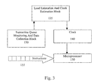
- FIG. 3 Another approach to estimating the clock frequency is to analyze the complexity of a set of n instructions 055, as shown in Figure 3 .
- an instruction queue monitoring and data collection block 130 collects information concerning the n instructions 155 which are queued in either queues 65 or 66.
- the set of n instructions may not be the next n instructions for execution by the microprocessor 150 in the queues 65, 66. To illustrate the following instructions are queued for execution. ..., I k +n+1, I k +n, I k +n-1, ..., I k +n, I k , ..., I;
- I is the instruction ready for execution.
- I k is the first queued instruction selected for analysis.
- the last instruction selected for analysis is I k +n.
- the resulting latency in the queue is k-i.
- a load estimation and clock estimation block 135 takes the collected data and estimates the required microprocessor performance. Based on the load estimation, a clock frequency is selected. To reduce processing, instead of analyzing the entire instruction set, a moving average of the instruction's intensity can be taken. The moving average allows for a new load estimate every instruction cycle.
- fuzzy logic controller uses fuzzy logic to group into fuzzy sets, such as five sets. To illustrate, five fuzzy sets based on estimated engine load are very high load, high load, medium load, low load and very low load.
- the fuzzy controller outputs a fuzzy variable. After defuzzication of the fuzzy variable, the clock frequency is determined. Additional inputs may be added to the fuzzy controller, such as the current clock frequency, the processor's draw of current and the temperature.
- a neural network controller is used. The control algorithm is learned by the neural network controller.
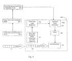
- a short term and a long term estimate may be used, as shown in Figure 4 .
- a short term estimation load estimation blocks 165, 170 Built onto the microprocessor chip 160 is a short term estimation load estimation blocks 165, 170.
- the short term blocks analyze a set of instructions 190 stored in a cache on the chip. Since the analysis is performed on a silicon level, the analysis is performed frequently.
- a long term load estimation blocks 200, 205, 210 analyze a set of instructions 195 queued off-chip, such as in an off-chip cache or in memory. Based on the long term analysis, a long term optimum clock estimation block 175 determines a preferred long term clocking frequency. The update of the long term frequency may be performed at the same or a lower rate then the short term analysis. On chip, an optimum clock estimation block determines the clock frequency based on the short term analysis and the preferred long term clocking frequency. Using this two tier approach, short term performance can be adjusted at a fast rate.
Landscapes
- Engineering & Computer Science (AREA)
- Theoretical Computer Science (AREA)
- Physics & Mathematics (AREA)
- General Engineering & Computer Science (AREA)
- General Physics & Mathematics (AREA)
- Software Systems (AREA)
- Power Sources (AREA)
- Executing Machine-Instructions (AREA)
Description
- The invention relates to power management in a computer system. More particularly, the invention relates to reducing power consumption of microprocessors in a computer system.
- Reducing power consumption in computer systems is highly desirable. Reduced power consumption decreases the heat generated by the system. As the packaging of computer systems becomes more compact, the dissipation of heat generated by the system is difficult. Accordingly, it is desirable to reduce the generated heat by reducing power consumption. Additionally, portable or handheld computer systems usually rely on portable power supplies or batteries. Lower power consumption prolongs the usage of a single battery or power supply without a recharge.
- The clock frequency of a microprocessor has a highly correlated relationship with the power consumption. The same microprocessor running with a higher clock frequency consumes more power and produces more heat than the same microprocessor running with a lower clock frequency. A typical computer system fixes the clock frequency of its microprocessor at initialization. Therefore, instead of running at the initialized clock frequency in both busy or idle modes, it is better to switch the system to a lower clock frequency if the computer is in an idle mode. One approach to triggering a reduction in clock frequency is to monitor inputs from input devices, such as a keyboard, mouse, or trackball. If there is no input from any of the input devices, for a predetermined period of time, the system will automatically switch from a normal system clock frequency to a slower one. The clock frequency returns to normal when the system receives an input from an input device, such as a keystroke or mouse movement. The input monitoring approach has drawbacks. Although the computer is not receiving an input, it may be engaged in heavy data processing, which a reduced clock frequency hinders this heavy processing.
- Another approach for triggering a reduction in clock frequency is to analyze the number of instructions executed by the microprocess for a predetermined period of time. If the number of executed instructions is low, the clock frequency is reduced. If the number of executed instructions increases, the clock frequency is increased to normal. One drawback to analyzing past instruction execution is that the past number of instructions may not accurately reflect future processing requirements. Accordingly, it is desirable to have alternative approaches to reduce power consumption.
-
US Patent No. 4670837 describes a clocked electrical system under the control of a processor. The processor controls the clock frequency based on the required processor activity and thus reduces the energy dissipated by the processor by using a lower clock frequency when the processor activity is low. -
EP-A-0789292 describes apparatus for estimating the power consumption of a microprocessor. The apparatus calculates power consumption values when an instruction to be executed is read from the main memory and from cache memories, and has means for distinguishing the memory from which instructions are read so that the total power consumption of the microprocessor can be calculated on the basis of the pre-calculated power consumption values for the various memories. -
EP-A-0785498 describes an apparatus for adjusting a CPU clock rate based on the dynamic operating characteristics of the CPU. The apparatus senses whether a setpoint interrupt condition exists by virtue of at least one such dynamic operating characteristic, when the CPU is operating at a first clock rate. If the interrupt condition exists, the clock rate is controlled relative to the first clock rate; if the interrupt condition does not exist, the process is repeated. - According to a first aspect of the invention, there is provided a method according to
claim 1. - According to a second aspect of the invention, there is provided a system according to claim 6.
-
-
Figure 1 is a simplified diagram illustrating the functional relationships among the microprocessor, system clock and instruction cache. -
Figure 2 is a functional block diagram of a computer system with separate reducing power consumption mechanisms for the microprocessor and the graphics processor. -
Figure 3 shows that the clock estimation device in detail blocks. -
Figure 4 shows a functional block diagram of a computer system with long term and short term load estimation mechanisms. - A computer system for reducing power consumption mechanism with various clock frequencies is shown in
Figure 1 . Theclock 55 provides a clocking signal for amicroprocessor 50. Themicroprocessor 50 may be a central processing unit (CPU), a graphics processor, such as a D3D engine, or any other processor. Themicroprocessor 50 has anassociated instruction cache 65. Thecache 65 stores instructions for execution by themicroprocessor 50. Thecache 65 may be on the same chip as themicroprocessor 50 or off chip. The system also has amemory buffer 66 storing instructions to be input to theinstruction cache 65. - A load and
estimation clock device 75 is used to control the clocking rate of the system. Theestimation device 75 controls the frequency of the clock signal being input into themicroprocessor 50. Based on a control signal from theestimation device 75, theclock 55 outputs the selected clocking frequency for the microprocessor among a plurality of available clock frequencies. - One approach to selecting the clock frequency is to analyze the queued instructions. Initially, the
microprocessor 50 is set to run at an initialization clock frequency. All instructions waiting to be executed by themicroprocessor 50 will be first queued at thememory buffer 66. The instructions queued in thememory buffer 66 are fed to theinstruction cache 65 to be queued for execution by themicroprocessor 50. Subsequent clock frequencies are estimated based on the number of queued instructions. - To further optimize the system's performance, the
estimation device 75 analyzes the types of instructions queued. Certain instructions require more intense processing than others. To compensate for the varying intensities, each instruction is weighted based on its intensity. - Additionally, the
estimation device 75 may use the measured microprocessor temperature, as determined by thetemperature monitor 70, to maintain the computer system at an acceptable range of operating temperature. If the temperature of themicroprocessor 50 is approaching an unacceptable level, the power consumption may need to be reduced to prevent circuit damage regardless of the backlog of instructions. To compensate for temperature, theclock estimation device 75 factors in the measured temperature. -
Figure 2 illustrates a computer system having separate monitoring mechanisms for amicroprocessor 90 and agraphics processor 115. Themicroprocessor 90 and the graphics processor 118 have its ownclock estimation device estimation device processor - One advantage to the individual monitoring of the two
processors estimation devices estimation device other devices processor estimation device 105 for thesmaller backlog processor microprocessors - Another approach to estimating the clock frequency is to analyze the complexity of a set of n instructions 055, as shown in
Figure 3 . Within theclock estimation device data collection block 130 collects information concerning then instructions 155 which are queued in eitherqueues microprocessor 150 in thequeues
..., Ik+n+1, Ik+n, Ik+n-1, ..., Ik+n, Ik, ..., I;
- I is the instruction ready for execution. Ik is the first queued instruction selected for analysis. According to 1x, the last instruction selected for analysis is Ik+n. The resulting latency in the queue is k-i. Based on the flexibility of the clock adjustment circuitry, the number of instructions n and algorithm latency k-I can be chosen to perform clock optimization frequently or in longer periods. A load estimation and
clock estimation block 135 takes the collected data and estimates the required microprocessor performance. Based on the load estimation, a clock frequency is selected. To reduce processing, instead of analyzing the entire instruction set, a moving average of the instruction's intensity can be taken. The moving average allows for a new load estimate every instruction cycle. - One approach to load and clock estimation uses a fuzzy logic controller. Using fuzzy logic, the n instructions are grouped into fuzzy sets, such as five sets. To illustrate, five fuzzy sets based on estimated engine load are very high load, high load, medium load, low load and very low load. The fuzzy controller outputs a fuzzy variable. After defuzzication of the fuzzy variable, the clock frequency is determined. Additional inputs may be added to the fuzzy controller, such as the current clock frequency, the processor's draw of current and the temperature. To more adaptively adjust the clock control algorithm, a neural network controller is used. The control algorithm is learned by the neural network controller.
- To enhance performance, a short term and a long term estimate may be used, as shown in
Figure 4 . Built onto themicroprocessor chip 160 is a short term estimation load estimation blocks 165, 170. The short term blocks analyze a set ofinstructions 190 stored in a cache on the chip. Since the analysis is performed on a silicon level, the analysis is performed frequently. - A long term load estimation blocks 200, 205, 210 analyze a set of
instructions 195 queued off-chip, such as in an off-chip cache or in memory. Based on the long term analysis, a long term optimumclock estimation block 175 determines a preferred long term clocking frequency. The update of the long term frequency may be performed at the same or a lower rate then the short term analysis. On chip, an optimum clock estimation block determines the clock frequency based on the short term analysis and the preferred long term clocking frequency. Using this two tier approach, short term performance can be adjusted at a fast rate.
Claims (7)
- A method for reducing power consumption in a computer system comprising a first and a second processor (90, 115), a first, second and third instructions queues and a first and a second estimation device (100, 105), wherein the first processor (90) is for general purpose and the second processor (115) is for graphic processing purpose, wherein the first and second processor (90, 115) is associated with the second and third instructions queue respectively for storing instructions for execution by the respective first and second processor (90, 115), wherein the first estimation device (100) controls the clock of the first processor and the second estimation device controls the clock of the second processor, the method comprising:queuing all instructions at the first instruction queue;distributing non graphic related instructions to be queued at the second instruction queue from which said first processor (90) executes queued instructions; anddistributing graphic related instructions to be queued at the third instruction queue from which said second processor (115) executes queued instructions;analyzing, by the first and second estimation device (100, 105), instructions stored in both the second and third instructions queue;determining a first and second load estimation by the first and second estimation device (100, 105), respectively, based on a respective result of the analyzing;selecting, by the first and second estimation device (100, 105), a respective clock rate for the first and second processor (90, 115) out of a plurality of clocking rates based on the determined first and second load estimation, respectively, in order to equalize the backlog of instructions of the first and second processors; andclocking the first and second processors (90, 115) at the respective selected clock rate.
- The method of claim 1, wherein the analysis result comprises a determination of the number of the queued instructions.
- The method of claim 1, wherein the analysis result comprises a determination of processing required by each queued instruction.
- The method of claim 1, wherein the load estimation is based on a temperature of the microprocessor.
- The method of claim 1, wherein determining a load estimation further comprising using the first number of instructions queued at said first instruction queue and the second number of instructions queued at said second instruction queue as separate control factors.
- A system having means for reducing power consumption in a computer system comprising a first and a second processor (90, 115), a first, second and third instructions queues and a first and a second estimation device (100, 105), wherein the first processor (90) is for general purpose and the second processor (115) is for graphic processing purpose, wherein the first and second processor (90, 115) are associated with the second and third instructions queue respectively for storing instructions for execution by the respective first and second processor (90, 115), wherein the first estimation device is adapted to control the clock of the first processor and the second estimation device is adapted to control the clock of the second processor, the system comprising:means for queuing all instructions at the first instruction queue;means for distributing non graphic related instructions to be queued at the second instruction queue from which said first microprocessor (90) executes queued instructions; andmeans for distributing graphic related instructions to be queued at the third instruction queue from which said second microprocessor (115) executes queued instructions;means for analyzing, embodied in the first and second estimation device (100, 105), instructions stored in both the second and third instructions queue;means for determining a first and second load estimation embodied in the first and second estimation device (100, 105), respectively, based on a respective result of the analyzing;means for selecting, embodied in the first and second estimation device (100, 105), of a respective clock rate for the first and second processor (90, 115) out of a plurality of clocking rates based on the respective determined load estimation, respectively, in order to equalize the backlog of instructions of the first and second processors; andmeans for clocking the first and second processor (90, 115) at the respective selected clock rate.
- The system of claim 6, wherein means for instructions queued in said first instruction queue and the instructions queued in said second instruction queue as separate control factors.
Applications Claiming Priority (2)
| Application Number | Priority Date | Filing Date | Title |
|---|---|---|---|
| US767086 | 2001-01-22 | ||
| US09/767,086 US6715089B2 (en) | 2001-01-22 | 2001-01-22 | Reducing power consumption by estimating engine load and reducing engine clock speed |
Publications (3)
| Publication Number | Publication Date |
|---|---|
| EP1237067A2 EP1237067A2 (en) | 2002-09-04 |
| EP1237067A3 EP1237067A3 (en) | 2004-09-29 |
| EP1237067B1 true EP1237067B1 (en) | 2016-01-13 |
Family
ID=25078428
Family Applications (1)
| Application Number | Title | Priority Date | Filing Date |
|---|---|---|---|
| EP02250339.5A Expired - Lifetime EP1237067B1 (en) | 2001-01-22 | 2002-01-18 | Reducing power consumption by estimating load and reducing clock speed |
Country Status (2)
| Country | Link |
|---|---|
| US (3) | US6715089B2 (en) |
| EP (1) | EP1237067B1 (en) |
Cited By (25)
| Publication number | Priority date | Publication date | Assignee | Title |
|---|---|---|---|---|
| US11425189B2 (en) * | 2019-02-06 | 2022-08-23 | Magic Leap, Inc. | Target intent-based clock speed determination and adjustment to limit total heat generated by multiple processors |
| US11445232B2 (en) | 2019-05-01 | 2022-09-13 | Magic Leap, Inc. | Content provisioning system and method |
| US11510027B2 (en) | 2018-07-03 | 2022-11-22 | Magic Leap, Inc. | Systems and methods for virtual and augmented reality |
| US11514673B2 (en) | 2019-07-26 | 2022-11-29 | Magic Leap, Inc. | Systems and methods for augmented reality |
| US11521296B2 (en) | 2018-11-16 | 2022-12-06 | Magic Leap, Inc. | Image size triggered clarification to maintain image sharpness |
| US11579441B2 (en) | 2018-07-02 | 2023-02-14 | Magic Leap, Inc. | Pixel intensity modulation using modifying gain values |
| US11598651B2 (en) | 2018-07-24 | 2023-03-07 | Magic Leap, Inc. | Temperature dependent calibration of movement detection devices |
| US11609645B2 (en) | 2018-08-03 | 2023-03-21 | Magic Leap, Inc. | Unfused pose-based drift correction of a fused pose of a totem in a user interaction system |
| US11624929B2 (en) | 2018-07-24 | 2023-04-11 | Magic Leap, Inc. | Viewing device with dust seal integration |
| US11630507B2 (en) | 2018-08-02 | 2023-04-18 | Magic Leap, Inc. | Viewing system with interpupillary distance compensation based on head motion |
| US11737832B2 (en) | 2019-11-15 | 2023-08-29 | Magic Leap, Inc. | Viewing system for use in a surgical environment |
| US11756335B2 (en) | 2015-02-26 | 2023-09-12 | Magic Leap, Inc. | Apparatus for a near-eye display |
| US11762623B2 (en) | 2019-03-12 | 2023-09-19 | Magic Leap, Inc. | Registration of local content between first and second augmented reality viewers |
| US11762222B2 (en) | 2017-12-20 | 2023-09-19 | Magic Leap, Inc. | Insert for augmented reality viewing device |
| US11776509B2 (en) | 2018-03-15 | 2023-10-03 | Magic Leap, Inc. | Image correction due to deformation of components of a viewing device |
| US11790554B2 (en) | 2016-12-29 | 2023-10-17 | Magic Leap, Inc. | Systems and methods for augmented reality |
| US11856479B2 (en) | 2018-07-03 | 2023-12-26 | Magic Leap, Inc. | Systems and methods for virtual and augmented reality along a route with markers |
| US11874468B2 (en) | 2016-12-30 | 2024-01-16 | Magic Leap, Inc. | Polychromatic light out-coupling apparatus, near-eye displays comprising the same, and method of out-coupling polychromatic light |
| US11885871B2 (en) | 2018-05-31 | 2024-01-30 | Magic Leap, Inc. | Radar head pose localization |
| US11927759B2 (en) | 2017-07-26 | 2024-03-12 | Magic Leap, Inc. | Exit pupil expander |
| US11953653B2 (en) | 2017-12-10 | 2024-04-09 | Magic Leap, Inc. | Anti-reflective coatings on optical waveguides |
| US12016719B2 (en) | 2018-08-22 | 2024-06-25 | Magic Leap, Inc. | Patient viewing system |
| US12033081B2 (en) | 2019-11-14 | 2024-07-09 | Magic Leap, Inc. | Systems and methods for virtual and augmented reality |
| US12164978B2 (en) | 2018-07-10 | 2024-12-10 | Magic Leap, Inc. | Thread weave for cross-instruction set architecture procedure calls |
| US12618952B2 (en) | 2018-10-12 | 2026-05-05 | Magic Leap, Inc. | Staging system to verify accuracy of a motion tracking system |
Families Citing this family (55)
| Publication number | Priority date | Publication date | Assignee | Title |
|---|---|---|---|---|
| US6941480B1 (en) | 2000-09-30 | 2005-09-06 | Intel Corporation | Method and apparatus for transitioning a processor state from a first performance mode to a second performance mode |
| US7085944B1 (en) | 2000-09-30 | 2006-08-01 | Intel Corporation | Power management by transmitting single multiplexed signal to multiple system components to change settings of internal performance registers in response to change in power source |
| JP2002215599A (en) * | 2001-01-18 | 2002-08-02 | Mitsubishi Electric Corp | Multiprocessor system and control method thereof |
| US6715089B2 (en) * | 2001-01-22 | 2004-03-30 | Ati International Srl | Reducing power consumption by estimating engine load and reducing engine clock speed |
| US20030100340A1 (en) * | 2001-03-16 | 2003-05-29 | Cupps Bryan T. | Novel personal electronics device with thermal management |
| US7231531B2 (en) * | 2001-03-16 | 2007-06-12 | Dualcor Technologies, Inc. | Personal electronics device with a dual core processor |
| US20020173344A1 (en) * | 2001-03-16 | 2002-11-21 | Cupps Bryan T. | Novel personal electronics device |
| US7184003B2 (en) * | 2001-03-16 | 2007-02-27 | Dualcor Technologies, Inc. | Personal electronics device with display switching |
| US7216242B2 (en) * | 2001-03-16 | 2007-05-08 | Dualcor Technologies, Inc. | Personal electronics device with appliance drive features |
| US20030153354A1 (en) * | 2001-03-16 | 2003-08-14 | Cupps Bryan T. | Novel personal electronics device with keypad application |
| US20030153353A1 (en) * | 2001-03-16 | 2003-08-14 | Cupps Bryan T. | Novel personal electronics device with simultaneous multi-processor operation |
| US20030163601A1 (en) * | 2001-03-16 | 2003-08-28 | Cupps Bryan T. | Novel personal electronics device with common application platform |
| TW548534B (en) * | 2001-04-12 | 2003-08-21 | Via Tech Inc | Control method for frequency raising and reducing of central processing unit using neural network |
| US6859886B1 (en) * | 2001-10-02 | 2005-02-22 | Lsi Logic Corporation | IO based embedded processor clock speed control |
| US7149909B2 (en) * | 2002-05-09 | 2006-12-12 | Intel Corporation | Power management for an integrated graphics device |
| US7256788B1 (en) * | 2002-06-11 | 2007-08-14 | Nvidia Corporation | Graphics power savings system and method |
| US7243217B1 (en) * | 2002-09-24 | 2007-07-10 | Advanced Micro Devices, Inc. | Floating point unit with variable speed execution pipeline and method of operation |
| US7882369B1 (en) * | 2002-11-14 | 2011-02-01 | Nvidia Corporation | Processor performance adjustment system and method |
| US7903116B1 (en) * | 2003-10-27 | 2011-03-08 | Nvidia Corporation | Method, apparatus, and system for adaptive performance level management of a graphics system |
| WO2006056824A2 (en) * | 2004-09-10 | 2006-06-01 | Freescale Semiconductor, Inc. | Apparatus and method for controlling voltage and frequency |
| US7282966B2 (en) * | 2004-09-28 | 2007-10-16 | Intel Corporation | Frequency management apparatus, systems, and methods |
| GB2446754B (en) * | 2005-12-06 | 2011-02-09 | Advanced Risc Mach Ltd | Energy management |
| US8250394B2 (en) * | 2006-03-31 | 2012-08-21 | Stmicroelectronics International N.V. | Varying the number of generated clock signals and selecting a clock signal in response to a change in memory fill level |
| US7783905B2 (en) * | 2006-06-13 | 2010-08-24 | Via Technologies Inc. | Method for reducing power consumption of a computer system in the working state |
| US8135966B2 (en) | 2006-06-22 | 2012-03-13 | Freescale Semiconductor, Inc. | Method and device for power management |
| DE602006020640D1 (en) * | 2006-07-28 | 2011-04-21 | Advanced Risc Mach Ltd | POWER MANAGEMENT IN A DATA PROCESSING DEVICE WITH MASTERS AND SLAVES |
| US7689849B2 (en) * | 2006-08-28 | 2010-03-30 | Ati Technologies Ulc | Reduction of power consumption by throttling processor requests |
| US8046565B2 (en) * | 2006-12-06 | 2011-10-25 | Kabushiki Kaisha Toshiba | Accelerator load balancing with dynamic frequency and voltage reduction |
| US8667198B2 (en) * | 2007-01-07 | 2014-03-04 | Apple Inc. | Methods and systems for time keeping in a data processing system |
| US7917784B2 (en) * | 2007-01-07 | 2011-03-29 | Apple Inc. | Methods and systems for power management in a data processing system |
| US9134782B2 (en) | 2007-05-07 | 2015-09-15 | Nvidia Corporation | Maintaining optimum voltage supply to match performance of an integrated circuit |
| WO2009047664A1 (en) * | 2007-10-09 | 2009-04-16 | St Wireless Sa | Non-recursive adaptive filter for predicting the mean processing performance of a complex system´s processing core |
| US8243085B2 (en) * | 2007-12-30 | 2012-08-14 | Intel Corporation | Boosting graphics performance based on executing workload |
| US8370663B2 (en) * | 2008-02-11 | 2013-02-05 | Nvidia Corporation | Power management with dynamic frequency adjustments |
| US20090235108A1 (en) * | 2008-03-11 | 2009-09-17 | Gold Spencer M | Automatic processor overclocking |
| US8484647B2 (en) * | 2009-07-24 | 2013-07-09 | Apple Inc. | Selectively adjusting CPU wait mode based on estimation of remaining work before task completion on GPU |
| US9256265B2 (en) | 2009-12-30 | 2016-02-09 | Nvidia Corporation | Method and system for artificially and dynamically limiting the framerate of a graphics processing unit |
| US9830889B2 (en) | 2009-12-31 | 2017-11-28 | Nvidia Corporation | Methods and system for artifically and dynamically limiting the display resolution of an application |
| US8417985B2 (en) | 2010-05-18 | 2013-04-09 | Plx Technology, Inc. | Adjusting system clock to faster speed upon receiving mass storage command and back to lower speed upon completion of all commands |
| US8839006B2 (en) | 2010-05-28 | 2014-09-16 | Nvidia Corporation | Power consumption reduction systems and methods |
| EP2482147B1 (en) * | 2011-01-31 | 2013-10-16 | Siemens Aktiengesellschaft | Method for adjusting the clock frequency of a microprocessor of an industrial automation component and automation component with a microprocessor with adjustable clock frequency |
| US20130326249A1 (en) * | 2011-06-09 | 2013-12-05 | Guillermo Navarro | Regulating power consumption of a mass storage system |
| JP5696603B2 (en) * | 2011-06-29 | 2015-04-08 | 富士通株式会社 | Computer system, power control method and program for computer system |
| US8707073B2 (en) * | 2011-08-31 | 2014-04-22 | International Business Machines Corporation | Energy-efficient polling loop |
| US8862924B2 (en) | 2011-11-15 | 2014-10-14 | Advanced Micro Devices, Inc. | Processor with power control via instruction issuance |
| US9105249B2 (en) * | 2011-12-29 | 2015-08-11 | Intel Corporation | Energy conservation in a controller using dynamic frequency selection |
| JP5880962B2 (en) * | 2012-06-12 | 2016-03-09 | ソニー株式会社 | Electronic apparatus, calculation method, program, and information processing apparatus |
| US9307494B2 (en) * | 2012-10-17 | 2016-04-05 | Industry-Academic Cooperation Foundation, Yonsei University | Apparatus and method for selecting processing speed of processor and wireless network |
| US9208755B2 (en) | 2012-12-03 | 2015-12-08 | Nvidia Corporation | Low power application execution on a data processing device having low graphics engine utilization |
| US9329666B2 (en) * | 2012-12-21 | 2016-05-03 | Advanced Micro Devices, Inc. | Power throttling queue |
| EP3161586B1 (en) * | 2014-06-26 | 2020-08-05 | Consiglio Nazionale Delle Ricerche | Method and system for regulating in real time the clock frequencies of at least one cluster of electronic machines |
| US9678529B2 (en) * | 2014-09-02 | 2017-06-13 | Nvidia Corporation | Efficiency-based clock frequency adjustment |
| US9940905B2 (en) * | 2015-02-03 | 2018-04-10 | Qualcomm Incorporated | Clock rate adjustment for processing unit |
| CN106304293B (en) * | 2016-08-30 | 2019-08-30 | 广东美的制冷设备有限公司 | Single-chip microcomputer control method and device for WiFi module |
| US12204792B2 (en) * | 2021-08-06 | 2025-01-21 | Micron Technology, Inc. | Adaptive throughput monitoring |
Family Cites Families (23)
| Publication number | Priority date | Publication date | Assignee | Title |
|---|---|---|---|---|
| US4670837A (en) * | 1984-06-25 | 1987-06-02 | American Telephone And Telegraph Company | Electrical system having variable-frequency clock |
| US4570837A (en) * | 1984-08-30 | 1986-02-18 | Martin Paul, Inc. | Adhesive tape dispensing holder |
| US5218704A (en) * | 1989-10-30 | 1993-06-08 | Texas Instruments | Real-time power conservation for portable computers |
| DE69233573T2 (en) * | 1991-04-03 | 2006-06-14 | Tagsys S A | The article sortation system |
| US5844415A (en) * | 1994-02-03 | 1998-12-01 | Massachusetts Institute Of Technology | Method for three-dimensional positions, orientation and mass distribution |
| EP0747872B1 (en) * | 1995-06-07 | 1999-03-03 | International Business Machines Corporation | Video processor with addressing mode control |
| US5815693A (en) * | 1995-12-15 | 1998-09-29 | National Semiconductor Corporation | Processor having a frequency modulated core clock based on the criticality of program activity |
| US5996084A (en) * | 1996-01-17 | 1999-11-30 | Texas Instruments Incorporated | Method and apparatus for real-time CPU thermal management and power conservation by adjusting CPU clock frequency in accordance with CPU activity |
| JP3618442B2 (en) * | 1996-02-08 | 2005-02-09 | 株式会社東芝 | Microprocessor power estimator device |
| US6114862A (en) * | 1996-02-14 | 2000-09-05 | Stmicroelectronics, Inc. | Capacitive distance sensor |
| US5774704A (en) * | 1996-07-29 | 1998-06-30 | Silicon Graphics, Inc. | Apparatus and method for dynamic central processing unit clock adjustment |
| US6483931B2 (en) * | 1997-09-11 | 2002-11-19 | Stmicroelectronics, Inc. | Electrostatic discharge protection of a capacitve type fingerprint sensing array |
| JP3573957B2 (en) * | 1998-05-20 | 2004-10-06 | インターナショナル・ビジネス・マシーンズ・コーポレーション | Operating speed control method of processor in computer and computer |
| US6313845B1 (en) * | 1998-06-30 | 2001-11-06 | 3Dlabs Inc. Ltd. | Method and apparatus for transporting information to a graphic accelerator card |
| JP2000122747A (en) * | 1998-10-12 | 2000-04-28 | Nec Corp | Device and method for controlling digital signal processing part |
| US6415388B1 (en) * | 1998-10-30 | 2002-07-02 | Intel Corporation | Method and apparatus for power throttling in a microprocessor using a closed loop feedback system |
| DE60032286T8 (en) * | 1999-06-10 | 2007-09-27 | Nippon Telegraph And Telephone Corp. | Device for recognizing surface shapes |
| JP4233698B2 (en) * | 1999-08-12 | 2009-03-04 | セイコーインスツル株式会社 | Fingerprint reading apparatus and method |
| CN1155794C (en) * | 1999-12-02 | 2004-06-30 | 株式会社三丰 | Static capacity type deflexion detecting apparatus |
| US6512381B2 (en) * | 1999-12-30 | 2003-01-28 | Stmicroelectronics, Inc. | Enhanced fingerprint detection |
| US6715089B2 (en) * | 2001-01-22 | 2004-03-30 | Ati International Srl | Reducing power consumption by estimating engine load and reducing engine clock speed |
| JP2003058872A (en) * | 2001-08-21 | 2003-02-28 | Sony Corp | Fingerprint detecting device, manufacturing method thereof and film forming device |
| JP2005326167A (en) * | 2004-05-12 | 2005-11-24 | Alps Electric Co Ltd | Capacitance detection type sensor |
-
2001
- 2001-01-22 US US09/767,086 patent/US6715089B2/en not_active Expired - Lifetime
-
2002
- 2002-01-18 EP EP02250339.5A patent/EP1237067B1/en not_active Expired - Lifetime
-
2004
- 2004-03-30 US US10/813,595 patent/US7167994B2/en not_active Expired - Lifetime
-
2006
- 2006-11-02 US US11/555,847 patent/US7610499B2/en not_active Expired - Lifetime
Cited By (38)
| Publication number | Priority date | Publication date | Assignee | Title |
|---|---|---|---|---|
| US12562004B2 (en) | 2015-02-26 | 2026-02-24 | Magic Leap, Inc. | Apparatus for a near-eye display |
| US11756335B2 (en) | 2015-02-26 | 2023-09-12 | Magic Leap, Inc. | Apparatus for a near-eye display |
| US12131500B2 (en) | 2016-12-29 | 2024-10-29 | Magic Leap, Inc. | Systems and methods for augmented reality |
| US11790554B2 (en) | 2016-12-29 | 2023-10-17 | Magic Leap, Inc. | Systems and methods for augmented reality |
| US11874468B2 (en) | 2016-12-30 | 2024-01-16 | Magic Leap, Inc. | Polychromatic light out-coupling apparatus, near-eye displays comprising the same, and method of out-coupling polychromatic light |
| US11927759B2 (en) | 2017-07-26 | 2024-03-12 | Magic Leap, Inc. | Exit pupil expander |
| US11953653B2 (en) | 2017-12-10 | 2024-04-09 | Magic Leap, Inc. | Anti-reflective coatings on optical waveguides |
| US12298473B2 (en) | 2017-12-10 | 2025-05-13 | Magic Leap, Inc. | Anti-reflective coatings on optical waveguides |
| US12366769B2 (en) | 2017-12-20 | 2025-07-22 | Magic Leap, Inc. | Insert for augmented reality viewing device |
| US11762222B2 (en) | 2017-12-20 | 2023-09-19 | Magic Leap, Inc. | Insert for augmented reality viewing device |
| US11908434B2 (en) | 2018-03-15 | 2024-02-20 | Magic Leap, Inc. | Image correction due to deformation of components of a viewing device |
| US11776509B2 (en) | 2018-03-15 | 2023-10-03 | Magic Leap, Inc. | Image correction due to deformation of components of a viewing device |
| US11885871B2 (en) | 2018-05-31 | 2024-01-30 | Magic Leap, Inc. | Radar head pose localization |
| US12001013B2 (en) | 2018-07-02 | 2024-06-04 | Magic Leap, Inc. | Pixel intensity modulation using modifying gain values |
| US11579441B2 (en) | 2018-07-02 | 2023-02-14 | Magic Leap, Inc. | Pixel intensity modulation using modifying gain values |
| US11510027B2 (en) | 2018-07-03 | 2022-11-22 | Magic Leap, Inc. | Systems and methods for virtual and augmented reality |
| US11856479B2 (en) | 2018-07-03 | 2023-12-26 | Magic Leap, Inc. | Systems and methods for virtual and augmented reality along a route with markers |
| US12164978B2 (en) | 2018-07-10 | 2024-12-10 | Magic Leap, Inc. | Thread weave for cross-instruction set architecture procedure calls |
| US12379981B2 (en) | 2018-07-10 | 2025-08-05 | Magic Leap, Inc. | Thread weave for cross-instruction set architectureprocedure calls |
| US11598651B2 (en) | 2018-07-24 | 2023-03-07 | Magic Leap, Inc. | Temperature dependent calibration of movement detection devices |
| US11624929B2 (en) | 2018-07-24 | 2023-04-11 | Magic Leap, Inc. | Viewing device with dust seal integration |
| US12247846B2 (en) | 2018-07-24 | 2025-03-11 | Magic Leap, Inc. | Temperature dependent calibration of movement detection devices |
| US11630507B2 (en) | 2018-08-02 | 2023-04-18 | Magic Leap, Inc. | Viewing system with interpupillary distance compensation based on head motion |
| US12254141B2 (en) | 2018-08-03 | 2025-03-18 | Magic Leap, Inc. | Unfused pose-based drift correction of a fused pose of a totem in a user interaction system |
| US11960661B2 (en) | 2018-08-03 | 2024-04-16 | Magic Leap, Inc. | Unfused pose-based drift correction of a fused pose of a totem in a user interaction system |
| US11609645B2 (en) | 2018-08-03 | 2023-03-21 | Magic Leap, Inc. | Unfused pose-based drift correction of a fused pose of a totem in a user interaction system |
| US12016719B2 (en) | 2018-08-22 | 2024-06-25 | Magic Leap, Inc. | Patient viewing system |
| US12618952B2 (en) | 2018-10-12 | 2026-05-05 | Magic Leap, Inc. | Staging system to verify accuracy of a motion tracking system |
| US11521296B2 (en) | 2018-11-16 | 2022-12-06 | Magic Leap, Inc. | Image size triggered clarification to maintain image sharpness |
| US11425189B2 (en) * | 2019-02-06 | 2022-08-23 | Magic Leap, Inc. | Target intent-based clock speed determination and adjustment to limit total heat generated by multiple processors |
| US11762623B2 (en) | 2019-03-12 | 2023-09-19 | Magic Leap, Inc. | Registration of local content between first and second augmented reality viewers |
| US11445232B2 (en) | 2019-05-01 | 2022-09-13 | Magic Leap, Inc. | Content provisioning system and method |
| US12267545B2 (en) | 2019-05-01 | 2025-04-01 | Magic Leap, Inc. | Content provisioning system and method |
| US12249035B2 (en) | 2019-07-26 | 2025-03-11 | Magic Leap, Inc. | System and method for augmented reality with virtual objects behind a physical surface |
| US11514673B2 (en) | 2019-07-26 | 2022-11-29 | Magic Leap, Inc. | Systems and methods for augmented reality |
| US12033081B2 (en) | 2019-11-14 | 2024-07-09 | Magic Leap, Inc. | Systems and methods for virtual and augmented reality |
| US12472007B2 (en) | 2019-11-15 | 2025-11-18 | Magic Leap, Inc. | Viewing system for use in a surgical environment |
| US11737832B2 (en) | 2019-11-15 | 2023-08-29 | Magic Leap, Inc. | Viewing system for use in a surgical environment |
Also Published As
| Publication number | Publication date |
|---|---|
| US6715089B2 (en) | 2004-03-30 |
| EP1237067A3 (en) | 2004-09-29 |
| US20050044435A1 (en) | 2005-02-24 |
| US7167994B2 (en) | 2007-01-23 |
| US20070208962A1 (en) | 2007-09-06 |
| EP1237067A2 (en) | 2002-09-04 |
| US7610499B2 (en) | 2009-10-27 |
| US20020099964A1 (en) | 2002-07-25 |
Similar Documents
| Publication | Publication Date | Title |
|---|---|---|
| US6715089B2 (en) | Reducing power consumption by estimating engine load and reducing engine clock speed | |
| EP1620783B1 (en) | Method and apparatus for dynamic power management in a processor system | |
| US8006108B2 (en) | Dynamic selection of group and device power limits | |
| EP2073097B1 (en) | Transitioning a processor package to a low power state | |
| US7779276B2 (en) | Power management in a power-constrained processing system | |
| US6513124B1 (en) | Method and apparatus for controlling operating speed of processor in computer | |
| US7472293B2 (en) | Network processor power management | |
| US8473647B2 (en) | Methods and apparatus for decreasing power consumption and bus activity | |
| US20030065961A1 (en) | Progressive CPU sleep state duty cycle to limit peak power of multiple computers on shared power distribution unit | |
| JPH1091298A (en) | Electric power self-inspection control circuit for function unit of microprocessor | |
| WO2008016791A1 (en) | System and method for controlling processor low power states | |
| US12445365B2 (en) | Technologies for performance monitoring and management with empty polling | |
| JP3742364B2 (en) | Clock frequency control method and electronic device | |
| US7975155B2 (en) | Apparatus and method for controlling voltage and frequency | |
| US8135966B2 (en) | Method and device for power management | |
| Kang et al. | Nmap: Power management based on network packet processing mode transition for latency-critical workloads | |
| JP2007172322A (en) | Distributed processing multiprocessor system, control method, multiprocessor interrupt control device, and program | |
| Zhang et al. | Power-aware processor scheduling under average delay constraints | |
| Guo et al. | AEP-D3QN: Adaptive Exploration and Penalty-Enhanced Dynamic Scheduling for 6G Edge Computing | |
| AU2008200446B2 (en) | Method and apparatus for dynamic power management in a processor system | |
| Guermouche et al. | Leveraging Application Characteristics for Energy Savings | |
| Yu et al. | A Dynamic Disk Drive Power Management Algorithm |
Legal Events
| Date | Code | Title | Description |
|---|---|---|---|
| PUAI | Public reference made under article 153(3) epc to a published international application that has entered the european phase |
Free format text: ORIGINAL CODE: 0009012 |
|
| AK | Designated contracting states |
Kind code of ref document: A2 Designated state(s): AT BE CH CY DE DK ES FI FR GB GR IE IT LI LU MC NL PT SE TR |
|
| AX | Request for extension of the european patent |
Free format text: AL;LT;LV;MK;RO;SI |
|
| PUAL | Search report despatched |
Free format text: ORIGINAL CODE: 0009013 |
|
| AK | Designated contracting states |
Kind code of ref document: A3 Designated state(s): AT BE CH CY DE DK ES FI FR GB GR IE IT LI LU MC NL PT SE TR |
|
| AX | Request for extension of the european patent |
Extension state: AL LT LV MK RO SI |
|
| 17P | Request for examination filed |
Effective date: 20050208 |
|
| AKX | Designation fees paid |
Designated state(s): DE FR GB |
|
| 17Q | First examination report despatched |
Effective date: 20050530 |
|
| 17Q | First examination report despatched |
Effective date: 20050530 |
|
| RAP1 | Party data changed (applicant data changed or rights of an application transferred) |
Owner name: QUALCOMM INCORPORATED |
|
| REG | Reference to a national code |
Ref country code: DE Ref legal event code: R079 Ref document number: 60247734 Country of ref document: DE Free format text: PREVIOUS MAIN CLASS: G06F0001320000 Ipc: G06F0009380000 |
|
| GRAP | Despatch of communication of intention to grant a patent |
Free format text: ORIGINAL CODE: EPIDOSNIGR1 |
|
| RIC1 | Information provided on ipc code assigned before grant |
Ipc: G06F 9/38 20060101AFI20150626BHEP |
|
| INTG | Intention to grant announced |
Effective date: 20150720 |
|
| GRAS | Grant fee paid |
Free format text: ORIGINAL CODE: EPIDOSNIGR3 |
|
| GRAA | (expected) grant |
Free format text: ORIGINAL CODE: 0009210 |
|
| REG | Reference to a national code |
Ref country code: FR Ref legal event code: PLFP Year of fee payment: 15 |
|
| AK | Designated contracting states |
Kind code of ref document: B1 Designated state(s): DE FR GB |
|
| REG | Reference to a national code |
Ref country code: GB Ref legal event code: FG4D |
|
| REG | Reference to a national code |
Ref country code: DE Ref legal event code: R096 Ref document number: 60247734 Country of ref document: DE |
|
| REG | Reference to a national code |
Ref country code: DE Ref legal event code: R097 Ref document number: 60247734 Country of ref document: DE |
|
| PLBE | No opposition filed within time limit |
Free format text: ORIGINAL CODE: 0009261 |
|
| STAA | Information on the status of an ep patent application or granted ep patent |
Free format text: STATUS: NO OPPOSITION FILED WITHIN TIME LIMIT |
|
| 26N | No opposition filed |
Effective date: 20161014 |
|
| REG | Reference to a national code |
Ref country code: FR Ref legal event code: PLFP Year of fee payment: 16 |
|
| REG | Reference to a national code |
Ref country code: FR Ref legal event code: PLFP Year of fee payment: 17 |
|
| PGFP | Annual fee paid to national office [announced via postgrant information from national office to epo] |
Ref country code: GB Payment date: 20201231 Year of fee payment: 20 Ref country code: FR Payment date: 20201223 Year of fee payment: 20 |
|
| PGFP | Annual fee paid to national office [announced via postgrant information from national office to epo] |
Ref country code: DE Payment date: 20201218 Year of fee payment: 20 |
|
| REG | Reference to a national code |
Ref country code: DE Ref legal event code: R071 Ref document number: 60247734 Country of ref document: DE |
|
| REG | Reference to a national code |
Ref country code: GB Ref legal event code: PE20 Expiry date: 20220117 |
|
| PG25 | Lapsed in a contracting state [announced via postgrant information from national office to epo] |
Ref country code: GB Free format text: LAPSE BECAUSE OF EXPIRATION OF PROTECTION Effective date: 20220117 |