EP1237052A2 - Electrographic image developing process with optimized developer mass velocity - Google Patents
Electrographic image developing process with optimized developer mass velocity Download PDFInfo
- Publication number
- EP1237052A2 EP1237052A2 EP02003200A EP02003200A EP1237052A2 EP 1237052 A2 EP1237052 A2 EP 1237052A2 EP 02003200 A EP02003200 A EP 02003200A EP 02003200 A EP02003200 A EP 02003200A EP 1237052 A2 EP1237052 A2 EP 1237052A2
- Authority
- EP
- European Patent Office
- Prior art keywords
- imaging member
- velocity
- developer
- electrographic printer
- toning shell
- Prior art date
- Legal status (The legal status is an assumption and is not a legal conclusion. Google has not performed a legal analysis and makes no representation as to the accuracy of the status listed.)
- Withdrawn
Links
Images

Classifications
-
- G—PHYSICS
- G03—PHOTOGRAPHY; CINEMATOGRAPHY; ANALOGOUS TECHNIQUES USING WAVES OTHER THAN OPTICAL WAVES; ELECTROGRAPHY; HOLOGRAPHY
- G03G—ELECTROGRAPHY; ELECTROPHOTOGRAPHY; MAGNETOGRAPHY
- G03G15/00—Apparatus for electrographic processes using a charge pattern
- G03G15/06—Apparatus for electrographic processes using a charge pattern for developing
- G03G15/08—Apparatus for electrographic processes using a charge pattern for developing using a solid developer, e.g. powder developer
- G03G15/09—Apparatus for electrographic processes using a charge pattern for developing using a solid developer, e.g. powder developer using magnetic brush
-
- G—PHYSICS
- G03—PHOTOGRAPHY; CINEMATOGRAPHY; ANALOGOUS TECHNIQUES USING WAVES OTHER THAN OPTICAL WAVES; ELECTROGRAPHY; HOLOGRAPHY
- G03G—ELECTROGRAPHY; ELECTROPHOTOGRAPHY; MAGNETOGRAPHY
- G03G13/00—Electrographic processes using a charge pattern
- G03G13/06—Developing
- G03G13/08—Developing using a solid developer, e.g. powder developer
- G03G13/09—Developing using a solid developer, e.g. powder developer using magnetic brush
-
- G—PHYSICS
- G03—PHOTOGRAPHY; CINEMATOGRAPHY; ANALOGOUS TECHNIQUES USING WAVES OTHER THAN OPTICAL WAVES; ELECTROGRAPHY; HOLOGRAPHY
- G03G—ELECTROGRAPHY; ELECTROPHOTOGRAPHY; MAGNETOGRAPHY
- G03G15/00—Apparatus for electrographic processes using a charge pattern
- G03G15/06—Apparatus for electrographic processes using a charge pattern for developing
- G03G15/08—Apparatus for electrographic processes using a charge pattern for developing using a solid developer, e.g. powder developer
- G03G15/09—Apparatus for electrographic processes using a charge pattern for developing using a solid developer, e.g. powder developer using magnetic brush
- G03G15/0921—Details concerning the magnetic brush roller structure, e.g. magnet configuration
Definitions
- the invention relates generally to processes for electrographic image development. More specifically, the invention relates to apparatus and methods for electrographic image development, wherein the image development process is optimized by setting the developer mass flow velocity with reference to the imaging member velocity.
- Electrographic printers typically employ a developer having two or more components, consisting of resinous, pigmented toner particles, magnetic carrier particles and other components. The developer is moved into proximity with an electrostatic image carried on an electrographic imaging member, whereupon the toner component of the developer is transferred to the imaging member, prior to being transferred to a sheet of paper to create the final image.
- Developer is moved into proximity with the imaging member by an electrically-biased, conductive toning shell, often a roller that may be rotated co-currently with the imaging member, such that the opposing surfaces of the imaging member and toning shell travel in the same direction.
- a multipole magnetic core Located adjacent the toning shell is a multipole magnetic core, having a plurality of magnets, that may be fixed relative to the toning shell or that may rotate, usually in the opposite direction of the toning shell.
- the developer is deposited on the toning shell and the toning shell rotates the developer into proximity with the imaging member, at a location where the imaging member and the toning shell are in closest proximity, referred to as the "toning nip.”
- the magnetic carrier component of the developer forms a "nap,” similar in appearance to the nap of a fabric, on the toning shell, because the magnetic particles form chains of particles that rise vertically from the surface of the toning shell in the direction of the magnetic field.
- the nap height is maximum when the magnetic field from either a north or south pole is perpendicular to the toning shell.
- Adjacent magnets in the magnetic core have opposite polarity and, therefore, as the magnetic core rotates, the magnetic field also rotates from perpendicular to the toning shell to parallel to the toning shell.
- the chains collapse onto the surface of the toning shell and, as the magnetic field again rotates toward perpendicular to the toning shell, the chains also rotate toward perpendicular again.
- the carrier chains appear to flip end over end and "walk" on the surface of the toning shell and, when the magnetic core rotates in the opposite direction of the toning shell, the chains walk in the direction of imaging member travel.
- the present invention solves these and other shortcomings of the prior art by providing a method and apparatus for generation of electrographic images in which the average developer mass velocity is within preferred ranges relative to the imaging member velocity.
- the invention provides an electrographic printer, including an imaging member moving at a predetermined velocity, a toning shell located adjacent the imaging member and defining an image development area therebetween, and a multipole magnetic core located adjacent the toning shell, wherein developer is caused to move through the image development area in the direction of imaging member travel at a developer mass velocity greater than about 37% of the imaging member velocity.
- the developer mass velocity is greater than about 50% of the imaging member velocity.
- the developer mass velocity is greater than about 75% of the imaging member velocity.
- the developer mass velocity is greater than about 90% of the imaging member velocity. In a still further embodiment, the developer mass velocity is between 40% and 130% of the imaging member velocity, and preferably between 90% and 110% of the imaging member velocity. In another embodiment, the developer mass velocity is substantially equal to the imaging member velocity. In yet another embodiment, the electrographic printer includes a cylindrical magnetic core or other configuration of magnetic field producing means that produces a magnetic field having a field vector in the toning nip that rotates in space.
- a further embodiment is a method for generating electrographic images, the method including providing an electrographic printer comprising an imaging member moving at a predetermined velocity, a toning shell located adjacent the imaging member and defining an image development area therebetween, and a multipole magnetic core located inside the toning shell, and causing developer to move through the image development area in the direction of imaging member travel at a developer mass velocity greater than about 37% of the imaging member velocity.
- the developer mass velocity is greater than about 50% of the imaging member velocity.
- the developer mass velocity is greater than about 75% of the imaging member velocity.
- the developer mass velocity is greater than about 90% of the imaging member velocity.
- the developer mass velocity is between about 40% and about 130% of the imaging member velocity, and more preferably between about 90% and about 110% of the imaging member velocity. In a still further embodiment, the developer mass velocity is substantially equal to the imaging member velocity.
- An additional embodiment provides an electrographic printer including an imaging member moving at a predetermined velocity, a toning shell located adjacent the imaging member and defining an image development area therebetween, and a multipole magnetic core located adjacent the toning shell, wherein developer is caused to move through the image development area in the direction of imaging member travel at a velocity such that the developer flow in gm/(in. sec.) divided by the developer mass area density in gm/in 2 is greater than about 37% of the imaging member velocity.
- the developer is caused to move through the image development area in the direction of imaging member travel at a velocity such that the developer flow in gm/(in. sec.) divided by the developer mass area density in gm/in 2 is between about 90% and 110% of the imaging member velocity.
- An additional embodiment provides an electrographic printer including an imaging member moving at a predetermined velocity, a toning shell located adjacent the imaging member and defining an image development area therebetween, and a multipole magnetic core located adjacent the toning shell, wherein developer is caused to move through the image development area in the direction of imaging member travel at a rate with excess free volume in the image development area to be between about 7% and about 93%, preferably between about 25% and about 75%, and more preferably about 50%.
- An additional embodiment provides a method for generating electrographic images including providing an electrographic printer comprising an imaging member moving at a predetermined velocity, a toning shell located adjacent the imaging member, and defining an image development area therebetween, and a multipole magnetic core located inside the toning shell and causing developer to move through the image development area in the direction of imaging member travel at a developer mass velocity such that there is substantially no relative motion in the process direction of the developer with reference to the imaging member, wherein the developer is caused to move in a direction normal to the direction of developer mass flow.
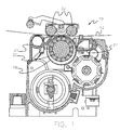
- Figures 1-5 depict an exemplary electrographic printing apparatus according to an aspect of the invention.
- An apparatus 10 for developing electrographic images is presented comprising an electrographic imaging member 12 on which an electrostatic image is generated, and a magnetic brush 14 comprising a rotating toning shell 18, a mixture 16 of hard magnetic carriers and toner (also referred to herein as "developer"), and a magnetic core 20.
- developer hard magnetic carriers and toner
- the magnetic core 20 comprises a plurality of magnets 21 of alternating polarity, located inside the toning shell 18 and rotating in the opposite direction of toning shell rotation, causing the magnetic field vector to rotate in space relative to the plane of the toning shell.
- the imaging member 12 is a photoconductor and is configured as a sheet-like film.
- the imaging member may be configured in other ways, such as a drum or as another material and configuration capable of retaining an electrostatic image, used in electrophotographic, ionographic or similar applications.
- the film imaging member 12 is relatively resilient, typically under tension, and a pair of backer bars 32 may be provided that hold the imaging member in a desired position relative to the toning shell 18, as shown in Figure 1.
- a metering skive 27 may be moved closer to or further away from the toning shell 18 to adjust the amount of toner delivered.
- the imaging member 12 is rotated at a predetermined imaging member 12 velocity in the process direction, i.e., the direction in which the imaging member travels through the system, and the toning shell 18 is rotated with a toning shell 18 surface velocity adjacent and co-directional with the imaging member 12 velocity.
- the toning shell 18 and magnetic core 20 bring the developer 16, comprising hard magnetic carrier particles and toner particles into contact with the imaging member 12.
- the imaging member 12 contains a dielectric layer and a conductive layer, is electrically grounded and defines a ground plane.
- the surface of the imaging member 12 facing the toning shell 18 can be treated at this point in the process as an electrical insulator with imagewise charge on its surface, while the surface of the toning shell 18 opposite that is an electrical conductor. Biasing the toning shell 18 relative to ground with a voltage creates an electric field that attracts toner particles to the electrographic image with a uniform toner density, the electric field being a maximum where the toning shell 18 is adjacent the imaging member 12.
- the imaging member 12 and the toning shell 18 define an area therebetween known as the toning nip 34, also referred to herein as the image development area.
- Developer 16 is delivered to the toning shell 18 upstream from the toning nip 34 and, as the developer 16 is applied to the toning shell 18, the average velocity of developer 16 through the narrow toning nip 34 is initially less than the developer 16 velocity on other parts of the toning shell 18. Therefore, developer 16 builds up immediately upstream of the toning nip 34, in a so-called rollback zone 35, until sufficient pressure is generated in the toning nip 34 to compress the developer 16 to the extent that it moves at the same mass velocity as the developer 16 on the rest of the toning shell 18.
- the magnetic brush 14 operates according to the principles described in United States Patents 4,473,029 and 4,546,060.
- the two-component dry developer composition of United States Patent 4,546,060 comprises charged toner particles and oppositely charged, magnetic carrier particles, which comprise a magnetic material exhibiting "hard" magnetic properties, as characterized by a coercivity of at least 300 gauss and also exhibit an induced magnetic moment of at least 20 EMU/gm when in an applied field of 1000 gauss, as disclosed.
- the toning station has a nominally 2" diameter stainless steel toning shell containing a magnetic core having fourteen poles, adjacent magnets alternating between north and south polarity.
- Each alternating north and south pole has a field strength of approximately 1000 gauss.
- the toner particles have a nominal diameter of 11.5 microns, while the hard magnetic carrier particles have a nominal diameter of approximately 26 microns and resistivity of 10 11 ohm-cm.
- the invention is not so limited, and could be practiced with any apparatus that subjects the carrier particles to a magnetic field vector that rotates in space or to a magnetic field of alternating direction, as for example, in a solenoid array.
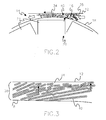
- the carrier particles form chains 40 under the influence of a magnetic field created by the rotating magnetic core 20, resulting in formation of a nap 38 as the magnetic carrier particles form chains of particles that rise from the surface of the toning shell 18 in the direction of the magnetic field, as indicated by arrows.
- the nap 38 height is maximum when the magnetic field from either a north or south pole is perpendicular to the toning shell 18, however, in the toning nip 34, the nap 38 height is limited by the spacing between the toning shell 18 and the imaging member 12.
- the magnetic field also rotates from perpendicular to the toning shell 18 to parallel to the toning shell 18.
- the chains 40 collapse onto the surface of the toning shell 18 and, as the magnetic field again rotates toward perpendicular to the toning shell 18, the chains 40 also rotate toward perpendicular again.
- each flip moreover, as a consequence of both the magnetic moment of the particles and the coercivity of the magnetic material, is accompanied by a rapid circumferential step by each particle in a direction opposite the movement of the magnetic core 20.
- the carrier chains 40 appear to flip end over end and "walk" on the surface of the toning shell 18.
- the chains 40 are forming, rotating, collapsing and re-forming in response to the pole transitions caused by the rotation of the magnetic core 20, thereby also agitating the developer 16, freeing up toner to interact with an electrostatic image carried by the imaging member 12, as discussed more fully below.
- Figure 4 represents development of a background area (no toner deposited)
- Figure 5 represents development of a toned area (toner deposited).
- the surface of the imaging member 12 is charged using methods known in the electrographic imaging arts to a negative static voltage, -750 VDC, for example, relative to ground.
- the shell is biased with a lesser negative voltage, -600 VDC, for example, relative to ground.
- the difference in electrical potential generates an electric field E that is maximum where the imaging member 12 is adjacent the shell 18.
- the electric field E is presented at numerous locations proximate the surface of the shell 18 with relative strength indicated by the size of the arrows.
- the toner particles are negatively charged in a DAD system, and are not drawn to the surface of the imaging member 12. However, the toner particles are drawn to the surface of the shell 18 where the electric field E is maximum (adjacent the imaging member 12).
- FIG. 5 the apparatus 10 of Figures 1 and 2 is shown with a discharged area of the imaging member 12 passing over the magnetic brush 14.
- the static voltage of -750 VDC on imaging member 12 has been discharged to a lesser static voltage, -150 VDC, for example, by methods known in the art such as a laser or LED printing head, without limitation.
- the sense of the electric field E is now reversed, and negative toner particles 46 are attracted to and adhere to the surface of the imaging member.
- a residual positive charge is developed in the mixture 16, which is carried away by the flow of the mixture 16.
- CAD charged area development
- the average mass velocity of the developer 16 should be matched to the imaging member 12 velocity. While not wishing to be bound to a particular theory, it is currently believed that the motion of the carrier chains 40 has another important influence on toning, in that when the chains 40 are rotating in the direction of the imaging member 12, the particles at the end of the chains 40 are impelled in a direction perpendicular to the imaging member 12, indicated by arrows in Fig. 3, imparting a developer 16 velocity component in this direction, perpendicular to the direction of developer 16 mass flow. Additionally, as the chains 40 move in this manner, any free developer 16 particles or clusters of developer 16 particles are "levered" in the direction of the imaging member 12, causing even free toner particles to be impelled in the direction of the imaging member.
- the average developer 16 mass velocity is exactly equal to the imaging member 12 velocity, there is no relative motion between the developer 16 and the imaging member 12 in the direction parallel to the imaging member 12, i.e., the "process direction," and the instantaneous relative velocity in the process direction of carrier particles relative to the imaging member 12 surface is essentially zero.
- the average developer 16 mass flow velocity in the process direction is much slower or much faster than the imaging member 12 velocity, a developer 16 velocity component parallel to the imaging member 12 is introduced, resulting in collisions with carrier particles moving parallel to the imaging member 12.
- Such collisions cause the toner particle(s) bound to the carrier particle to become freed, moving substantially parallel to the imaging member 12, interacting with the imaging member 12, particularly where the external field is low, such as background areas, and causing potentially severe image quality problems.
- the toner particles remain under the influence of the external electric field and are directed by the field toward or away from the imaging member 12, depending on the charge on a particular area of the imaging member 12.
- toner is deposited onto the electrostatic image carried by the imaging member 12 and scavenged back into the developer 16 simultaneously. By matching the actual mass velocity of the developer 16 with the velocity of the imaging member 12, such scavenging is minimized.
- the average developer 16 mass velocity is within preferred ranges with respect to the imaging member 12 velocity.
- the developer mass velocity is within the range of about 40% to about 130% of the imaging member 12 velocity and, more preferably is between about 75% to about 125% of the imaging member 12 velocity, more preferably, is between about 90% to about 110% of the imaging member 12 velocity, and in a preferred embodiment is substantially equal to the imaging member 12 velocity.
- optimal developer mass velocity is calculated for a given setpoint profile and the optimal settings for the toning shell 18 speed and magnetic core 20 speed are calculated to allow the developer mass velocity at those settings to be matched to the imaging member 12 velocity.
- the movement of the developer and, thus, the developer mass flow velocity can be seen as the sum of the rotation of the toning shell 18 carrying the developer 16, and the movement resulting from walking of the carrier chains 40 in response to pole transitions of the rotating magnetic core 20. These terms are summed because rotation of the toning shell 18 increases the frequency of pole transitions in the frame of reference of the toning shell 18.
- the chain walk speed depends on the distance "walked" during each pole transition and the frequency of such transitions, a direct result of the rotational speed of the magnetic core 20.
- the chain walk length i.e., the distance the carrier chains walk during each magnetic pole transition, also depends on the amount of excess free volume on the toning shell 18 or in the toning nip 34. Excess free volume is defined as the empty space in the developer nap 38 or in the toning nip 34 not occupied by toner or carrier or the structure the toner and carrier form when clustered together on the open, unbounded areas of the toning shell 18 or under the compressive forces exerted in the toning nip 34. Inside the toning nip 34, the excess free volume is limited by the spacing between the imaging member 12 and the toning shell 18.
- the amount of excess free volume determines the distance a given carrier chain 40 is able to walk.
- a carrier chain 40 disposed in 100% excess free volume can walk 180°, while a carrier chain 40 disposed in 0% excess free volume cannot walk at all.
- the more realistic situation of 50% excess free volume allows a carrier chain 40 to walk essentially 90°.
- the action of the carrier particle chains 40 forming, rotating and collapsing acts to agitate the developer 16, freeing toner particles from the carrier particles to interact with the imaging member 12. Nap 38 density and agitation are optimized at an excess free volume of 50%.
- the total volume per unit area corresponds to the nap 38 height, while inside the toning nip 34, the total volume per unit area is determined by the imaging member 12 spacing from the toning shell 18. In an exemplary embodiment, this spacing is nominally 0.014" but, given the flexibility of the film imaging member 12, the spacing is actually about 0.018".
- the fraction of volume occupied by the toner and carrier particles in the toning nip 34 may be calculated by assuming that the volume in the toning nip 34 is limited by the actual spacing of the imaging member 12 from the toning shell 18 of 0.018", calculating the actual volume occupied by each developer particle, and dividing this volume by the packing fraction, f, for dense randomly packed spheres and dividing by the total area available. For dense random packing, f ⁇ 0.6.
- N T DMAD x TC/( ⁇ T V T )
- N C DMAD x (1 - TC)/( ⁇ C V C )
- DMAD the developer mass area density
- TC toner content of the developer
- ⁇ T density of the toner particles
- ⁇ C density of the carrier particles
- the amount of available excess free volume, both in and out of the toning nip, is thus largely dependent on the degree to which the toner particles are able to fit into the voids created in packing of the carrier particles.
- the volume taken up by the developer is almost entirely dependent on the carrier particles. It may be seen, however, that, as the diameter of the toner particles increases relative to the diameter of the carrier particles, the ability of the toner particles to fit into the voids in the carrier particle packing structure diminishes and the toner particles increasingly contribute to the overall developer volume, decreasing free volume. In other words, if the toner particles are much smaller in diameter than the carrier particles, the toner particles are much smaller than these void structures and easily fit within the voids, and the excess free volume results essentially from the size of the carrier particles, with little or no contribution from the toner particles, and k is essentially 0.
- the toner particles are sized relative to the carrier particles such that the toner particles are large enough that they either just fit within the void or are slightly too large to fit within the void, the toner particles contribute to the overall excess free volume, and k approaches 1.
- k 1.
- the packing fraction, f is less than 0.6. It may be assumed that the packing structure of the nap outside the toning nip 34 results from magnetic attraction by the carrier particles and that relatively large toner particles will occupy voids in the packing structure of the carrier particles larger in size than the average toner particle and smaller in size than the average carrier particle.
- V F 1 - (kN T jV C + N C V C )/(fH) where H is the measured nap height.
- Parameter j is the average void size of j x V C that is occupied by a toner particle outside the toning nip 34, and V T /V C ⁇ j ⁇ 1.
- V T /V C 0.09
- j 0.6
- the above equations may be used to derive the desired developer mass velocity, which may then be matched to the imaging member velocity, either by manipulating the imaging member velocity to match the developer velocity or by manipulating the toning shell velocity and/or magnetic core velocity and or skive spacing 27 to adjust the developer mass velocity to the imaging member velocity.
- developer mass velocity, V dev was determined by dividing the developer flow rate by the developer mass area density, DMAD.
- the developer flow rate (g/in sec.) was measured on a benchtop toning station by running the toning station and collecting the developer from the toning shell in a 1 inch wide hopper for a fixed time, typically 0.5 seconds. The amount of developer collected per inch of hopper is divided by the time to determine the developer flow rate.
- DMAD was determined by abruptly stopping the toning station, placing a template having a one square inch cutout over the toning shell and removing the developer inside the cutout with a magnet or a vacuum. The collected developer was weighed and the mass was divided by the area to yield DMAD (g/in 2 ).
- Nap height was measured on a benchtop toning station using a Keyence LX2-1 laser and detector (Keyence Corporation of America, 649 Gotham Parkway, Carlstadt, NJ 07072). This device produces a voltage based on the height of the transmitted laser beam, comparing the height of the beam in the presence and absence of an intervening obstruction to determine the height of the obstruction, in this case the developer nap. The maximum difference between the two measurements indicates the height of the developer nap.
- the toner used in these examples had a volume average diameter of approximately 11.5 microns, with individual particles having a density of approximately 1 g/cc.
- the magnetic carrier used in these examples had a volume average diameter of approximately 26 microns and individual carrier particles had a density of approximately 3.5 g/cc.
- the toner concentration of the developer was 10% by weight, and the imaging member spacing was nominally set at 0.014 inches, although given the flexibility of the imaging member, the actual spacing was approximately 0.018 inches.
- the first setpoints approximate a commercial toning station operating at 110 pages per minute (ppm), wherein the linear velocity of the developer was matched to the imaging member speed, i.e., where the shell speed and magnetic core speed were set to make the velocity at the end of a carrier particle chain in the toning nip equal to the velocity of the imaging member when the end of the carrier chain was moving parallel to the imaging member.
- the second setpoints were determined as set forth herein, for 142 ppm.
- Type Film Speed (inches/sec) Skive Spacing Shell Speed (inches/sec) Shell speed (rpm) Core Speed (rpm) 110 ppm 17.48 0.031" 6.3 60 1100 142 ppm 23.04 0.025" 17.23 165 1100
- Type Film Speed (inches/sec) Measured V DEV Nip Free Volume Fraction Calculated V DEV Free Volume Outside Nip Calculated V DEV Outside Nip 110 ppm 17.48 6.43 0.05 6.97 0.05 7.00 142 ppm 23.04 24.54 0.52 24.52 0.52 24.52
- Type Film Speed (inches/sec) Nap Height Dev. flow (g/in sec) DMAD (g/in 2 ) V dev (in/sec) 110 ppm 17.48 0.04804" 3.02 0.47 6.43 142 ppm 23.04 0.04791" 5.89 0.24 24.54
- the invention can be used with electrophotographic or electrographic images.
- the invention can be used with imaging elements or imaging members in either web or drum formats. Optimized setpoints for some embodiments may be attained using reflection density instead of transmission density, and the exact values of optimum setpoints may depend on the geometry of particular embodiments or particular characteristics of development in those embodiments. It is therefore intended to include within the invention all such variations and modifications as fall within the scope of the appended claims and equivalents thereof.
Landscapes
- Physics & Mathematics (AREA)
- General Physics & Mathematics (AREA)
- Dry Development In Electrophotography (AREA)
- Magnetic Brush Developing In Electrophotography (AREA)
Abstract
Description
wherein the developer is caused to move in a direction normal to the direction of developer mass flow.
- FIG. 1
- presents a side view of an apparatus for developing electrographic images, according to an aspect of the invention.
- FIG. 2
- presents a side cross-sectional view of an apparatus for developing electrographic images, according to an aspect of the present invention.
- FIG. 3
- presents a diagrammatic view of the toning nap created by the operation of the apparatus depicted in Fig. 2.
- FIG. 4
- presents a side schematic view of a discharged area development configuration of the Figure 1 apparatus with a background area passing over a magnetic brush.
- FIG. 5
- presents a side schematic view of a discharged area development configuration of the Figure 1 apparatus with an area that is being toned passing over a magnetic brush.
| Type | Film Speed (inches/sec) | Skive Spacing | Shell Speed (inches/sec) | Shell speed (rpm) | Core Speed (rpm) |
| 110 ppm | 17.48 | 0.031" | 6.3 | 60 | 1100 |
| 142 ppm | 23.04 | 0.025" | 17.23 | 165 | 1100 |
| Type | Film Speed (inches/sec) | Measured VDEV | Nip Free Volume Fraction | Calculated VDEV | Free Volume Outside Nip | Calculated VDEV Outside Nip |
| 110 ppm | 17.48 | 6.43 | 0.05 | 6.97 | 0.05 | 7.00 |
| 142 ppm | 23.04 | 24.54 | 0.52 | 24.52 | 0.52 | 24.52 |
| Type | Film Speed (inches/sec) | Nap Height | Dev. flow (g/in sec) | DMAD (g/in2) | Vdev (in/sec) |
| 110 ppm | 17.48 | 0.04804" | 3.02 | 0.47 | 6.43 |
| 142 ppm | 23.04 | 0.04791" | 5.89 | 0.24 | 24.54 |
- 10
- apparatus for developing electrographic images
- 12
- electrographic image member
- 14
- magnetic brush
- 16
- mixture of hard magnetic carrier and toner (developer)
- 18
- rotating toning shell
- 20
- magnetic core
- 21
- magnet
- 27
- metering skive
- 32
- backer bar
- 34
- toning nip (image development area)
- 35
- rollback zone
- 38
- nap
- 40
- chain
- 46
- negative toner particles
Claims (38)
- An electrographic printer (10), comprising:wherein developer (16) is caused to move through the image development area (34) in the direction of imaging member travel at a developer mass velocity greater than about 37% of the imaging member velocity.an imaging member (12) moving at a predetermined velocity, a toning shell (18) located adjacent the imaging member (12) and defining an image development area (34) therebetween; anda multipole magnetic core (20) located adjacent the toning shell (18);
- An electrographic printer according to claim 1, wherein the toning shell (18) is a rotating toning shell and is rotating such that the toning surface opposite the imaging member (12) travels cocurrently with the imaging member (12) and wherein the multiple magnetic core (20) is located inside the toning shell (18).
- An electrographic printer according to claim 2, wherein the magnetic core (20) is a rotating core and is rotating in a direction opposite to the direction of the toning shell rotation.
- The electrographic printer of claim 1 or 2 or 3, wherein the developer mass velocity is greater than about 50% of the imaging member velocity.
- The electrographic printer of claim 1 or 2 or 3, wherein the developer mass velocity is greater than about 75% of the imaging member velocity.
- The electrographic printer of claim 1 or 2 or 3, wherein the developer mass velocity is greater than about 90% of the imaging member velocity.
- The electrographic printer of claim 1 or 2 or 3, wherein the developer mass velocity is between about 40% and about 130% of the imaging member velocity.
- The electrographic printer of claim 1 or 2 or 3, wherein the developer mass velocity is between about 75% and about 125% of the imaging member velocity.
- The electrographic printer of claim 1 or 2 or 3, wherein the developer mass velocity is between about 90% and about 110% of the imaging member velocity.
- The electrographic printer of claim 1 or 2 or 3, wherein the developer mass velocity is substantially equal to the imaging member velocity.
- The electrographic printer of claim 1 or 2 or 3, wherein the magnetic core (20) produces a magnetic field having a field vector that rotates in space.
- A method for generating electrographic images, the method comprising the steps of:a) providing an electrographic printer (10) comprising an imaging member (12) moving at a predetermined velocity, a toning shell (18) located adjacent the imaging member (12) and defining an image development area (34) therebetween, and a multipole magnetic core (20) located inside the toning shell (18);b) causing developer (16) to move through the image development area (34) in the direction of imaging member travel at a developer mass velocity greater than about 37% of the imaging member velocity.
- A method for generating electrographic images, the method comprising the steps of:a) providing an electrographic printer (10) comprising an imaging member (12) moving at a predetermined velocity, a rotating toning shell (18) located adjacent the imaging member (12), and defining an image development area therebetween, the toning shell (18) rotating in a direction such that the surface of the toning shell (18) opposite the imaging member travels in the direction of imaging member travel, and a multipole magnetic core (20) located inside the toning shell (18);b) causing developer to move through the image development area in the direction of imaging member travel at a developer mass velocity greater than about 37% of the imaging member velocity.
- The method of claim 12 or 13, wherein the developer mass velocity is greater than about 50% of the imaging member velocity.
- The method of claim 12 or 13, wherein the developer mass velocity is greater than about 75% of the imaging member velocity.
- The method of claim 12 or 13, wherein the developer mass velocity is greater than about 90% of the imaging member velocity.
- The method of claim 12 or 13, wherein the developer mass velocity is between about 40% and about 130% of the imaging member velocity.
- The method of claim 12 or 13, wherein the developer mass velocity is between about 75% and about 125% of the imaging member velocity.
- The method of claim 12 or 13, wherein the developer mass velocity is between about 90% and about 110% of the imaging member velocity.
- The method of claim 12 or 13, wherein the developer mass velocity is substantially equal to the imaging member velocity.
- An electrographic printer, comprising:wherein developer (16) is caused to move through the image development area in the direction of imaging member travel at a velocity such that the developer flow in gm/(in. sec.) divided by the developer mass area density in gm/in2 is greater than about 37% of the imaging member velocity.an imaging member (12) moving at a predetermined velocity, a toning shell (18) located adjacent the imaging member (12) and defining an image development area (34) therebetween; anda multipole magnetic core (20) located adjacent the toning shell (18);
- The electrographic printer of claim 21, wherein the developer (16) is caused to move through the image development area in the direction of imaging member travel at a velocity such that the developer flow in gm/(in. sec.) divided by the developer mass area density in gm/in2 is between about 75% and 125% of the imaging member velocity.
- The electrographic printer of claim 21, wherein the developer (16) is caused to move through the image development area in the direction of imaging member travel at a velocity such that the developer flow in gm/(in. sec.) divided by the developer mass area density in gm/in2 is between about 90% and 110% of the imaging member velocity.
- The electrographic printer of claim 21, wherein the developer (16) is caused to move through the image development area in the direction of imaging member travel at a velocity such that the developer flow in gm/(in. sec.) divided by the developer mass area density in gm/in2 is substantially equal to the imaging member velocity.
- An electrographic printer, comprising:wherein developer (16) is caused to move through the image development area in the direction of imaging member travel with excess free volume in the image development area between about 7% and about 93%.an imaging member (12) moving at a predetermined velocity, a toning shell (18) located adjacent the imaging member (12) and defining an image development area therebetween; anda multipole magnetic core (20) located adjacent the toning shell;
- The electrographic printer of claim 25, wherein developer (16) is caused to move through the image development area in the direction of imaging member travel with excess free volume in the image development area between about 25% and about 75%.
- The electrographic printer of claim 25, wherein developer (16) is caused to move through the image development area in the direction of imaging member travel with excess free volume in the image development area is about 50%.
- The electrographic printer of claim 25, wherein the percentage of excess free volume in the toning nip is determined by the equation VF = I - (kNTVT + NCVC)/(fL).
- The electrographic printer of claim 25, wherein the percentage of excess free volume on the toning shell is determined by the equation VF = 1 - (kNTjVC + NCVC)/(fH).
- The electrographic printer of claim 28 wherein k is equal to about 1.0.
- The electrographic printer of claim 28 wherein k is between about 0.0 and about 1.0.
- The electrographic printer of claim 29 wherein k is equal to about 1.0.
- The electrographic printer of claim 29 wherein k is between about 0.0 and about 1.0.
- A method for generating electrographic images, the method comprising the steps of:a) providing an electrographic printer (10) comprising an imaging member (12) moving at a predetermined velocity, a toning shell (18) located adjacent the imaging member, and defining an image development area therebetween, and a multipole magnetic core (20) located inside the toning shell (18);b) causing developer (16) to move through the image development area (12) in the direction of imaging member (12) travel at a developer mass velocity that there is substantially no relative motion of the developer in the process direction with reference to the imaging member (12); andc) developer is caused to move in a direction normal to the direction of developer mass flow by agitation.
- An electrographic printer, comprising:wherein developer (16) is caused to move on the toning shell in the process direction with an excess free volume fraction between about 7% and about 93%.an imaging member (12) moving at a predetermined velocity, a toning shell (18) located adjacent the imaging member (12) and defining an image development area therebetween; anda multipole magnetic core (20) located adjacent the toning shell;
- The electrographic printer of claim 35, wherein the excess free volume fraction is between about 25% and about 75%.
- The electrographic printer of claim 35, wherein the excess free volume fraction is about 50%.
- The electrographic printer of claim 35, wherein the imaging member spacing from the toning shell and the nap height conform to the equation
L/H ≥ (kNTVT + NCVC)/(kNTjVc + NCVC), where L is the spacing between the imaging member and the toning shell, and H is the nap height.
Applications Claiming Priority (6)
| Application Number | Priority Date | Filing Date | Title |
|---|---|---|---|
| US855985 | 1986-04-24 | ||
| US28758301P | 2001-02-28 | 2001-02-28 | |
| US287583P | 2001-02-28 | ||
| US27787601P | 2001-03-22 | 2001-03-22 | |
| US09/855,985 US6728503B2 (en) | 2001-02-28 | 2001-05-15 | Electrophotographic image developing process with optimized average developer bulk velocity |
| US277876P | 2009-09-30 |
Publications (2)
| Publication Number | Publication Date |
|---|---|
| EP1237052A2 true EP1237052A2 (en) | 2002-09-04 |
| EP1237052A3 EP1237052A3 (en) | 2006-05-10 |
Family
ID=27402950
Family Applications (1)
| Application Number | Title | Priority Date | Filing Date |
|---|---|---|---|
| EP02003200A Withdrawn EP1237052A3 (en) | 2001-02-28 | 2002-02-19 | Electrographic image developing process with optimized developer mass velocity |
Country Status (4)
| Country | Link |
|---|---|
| US (1) | US6728503B2 (en) |
| EP (1) | EP1237052A3 (en) |
| JP (1) | JP2002268389A (en) |
| CA (1) | CA2373978C (en) |
Cited By (1)
| Publication number | Priority date | Publication date | Assignee | Title |
|---|---|---|---|---|
| US6728503B2 (en) * | 2001-02-28 | 2004-04-27 | Heidelberger Druckmaschinen Ag | Electrophotographic image developing process with optimized average developer bulk velocity |
Families Citing this family (61)
| Publication number | Priority date | Publication date | Assignee | Title |
|---|---|---|---|---|
| WO2001088628A1 (en) * | 2000-05-17 | 2001-11-22 | Heidelberg Digital, L.L.C. | Electrostatic image developing process with optimized setpoints |
| US6946230B2 (en) | 2001-11-13 | 2005-09-20 | Heidelberger Druckmaschinen Ag | Electrostatic image developing processes and compositions |
| US7035576B2 (en) * | 2002-09-19 | 2006-04-25 | Ricoh Company, Ltd. | Method and apparatus of developing a latent image formed on a surface of an image carrier |
| US20040247357A1 (en) * | 2003-03-27 | 2004-12-09 | Frauens Michael W. | Method and system for wide format toning |
| US6959162B2 (en) * | 2003-03-31 | 2005-10-25 | Eastman Kodak Company | Electrographic image developing apparatus and process |
| US20060150902A1 (en) * | 2004-03-09 | 2006-07-13 | Eastman Kodak Company | Powder coating apparatus and method of powder coating using an electromagnetic brush |
| US7481884B2 (en) * | 2004-03-09 | 2009-01-27 | Eastman Kodak Company | Powder coating apparatus and method of powder coating using an electromagnetic brush |
| US20060230273A1 (en) * | 2005-04-08 | 2006-10-12 | Eastman Kodak Company | Hidden MIRC printing for security |
| US20060250656A1 (en) * | 2005-05-05 | 2006-11-09 | Eastman Kodak Company | Printing system, process, and product with a variable watermark |
| US7426361B2 (en) | 2005-09-01 | 2008-09-16 | Eastman Kodak Company | Developer mixing apparatus having four ribbon blenders |
| US7885584B2 (en) * | 2007-06-29 | 2011-02-08 | Eastman Kodak Company | Self-cleaning electrophotographic toning roller system |
| US8204411B2 (en) | 2009-07-31 | 2012-06-19 | Eastman Kodak Company | Electrographic image developing apparatus and method for developing including compensation for slippage |
| US8224209B2 (en) * | 2009-08-18 | 2012-07-17 | Eastman Kodak Company | High-frequency banding reduction for electrophotographic printer |
| US8311463B2 (en) * | 2009-08-18 | 2012-11-13 | Eastman Kodak Company | Method and system to reduce high-frequency banding for electrophotographic development stations |
| US20110170914A1 (en) * | 2010-01-14 | 2011-07-14 | Grabb Dennis J | Magnetic arrangement in a development roller of an electrostatographic printer |
| US8204413B2 (en) | 2010-06-30 | 2012-06-19 | Eastman Kodak Company | Printing job with developer removal |
| US8315532B2 (en) | 2010-06-30 | 2012-11-20 | Eastman Kodak Company | Reducing background development in electrophotographic printer |
| US20120027430A1 (en) | 2010-07-30 | 2012-02-02 | Brown Kenneth J | Measuring developer density in an electrophotographic system |
| US8358942B2 (en) | 2010-07-30 | 2013-01-22 | Eastman Kodak Company | Electrophotographic developer toner concentration measurement |
| US8380091B2 (en) | 2010-07-30 | 2013-02-19 | Eastman Kodak Company | Resonant-frequency measurement of electrophotographic developer density |
| US20120027432A1 (en) | 2010-07-30 | 2012-02-02 | Brown Kenneth J | Electrophotographic developer flow rate measurement |
| US8369717B2 (en) | 2010-08-27 | 2013-02-05 | Eastman Kodak Company | Determining developer toner concentration in electrophotographic printer |
| US8582988B2 (en) | 2010-09-27 | 2013-11-12 | Eastman Kodak Company | Effectively using a consumable in two printers |
| US8564861B2 (en) | 2010-11-30 | 2013-10-22 | Eastman Kodak Company | Providing calibration data for printer |
| US8406673B2 (en) | 2010-12-10 | 2013-03-26 | Eastman Kodak Company | Rotatable member cleaner for electrophotographic printer |
| JP2012145641A (en) * | 2011-01-07 | 2012-08-02 | Konica Minolta Business Technologies Inc | Image forming apparatus |
| US8422919B2 (en) | 2011-01-27 | 2013-04-16 | Eastman Kodak Company | Supplying electrophotographic toning member using ribbon blender |
| US8431313B2 (en) | 2011-01-31 | 2013-04-30 | Eastman Kodak Company | Balancing charge area developed and transferred toner |
| US8652741B2 (en) | 2011-01-31 | 2014-02-18 | Eastman Kodak Company | Enhancement of discharged area developed toner layer |
| US8652740B2 (en) | 2011-01-31 | 2014-02-18 | Eastman Kodak Company | Balancing discharge area developed and transferred toner |
| US8543030B2 (en) | 2011-02-14 | 2013-09-24 | Eastman Kodak Company | Electrophotographic printer with dust seal |
| US8565628B2 (en) | 2011-03-04 | 2013-10-22 | Eastman Kodak Company | Electrophotographic non-uniformity compensation using intentional periodic variation |
| US8693907B2 (en) | 2011-03-31 | 2014-04-08 | Eastman Kodak Company | Dual toner printing with discharge area development |
| US8693906B2 (en) | 2011-03-31 | 2014-04-08 | Eastman Kodak Company | Dual toner printing with charge area development |
| US8676072B2 (en) | 2011-03-31 | 2014-03-18 | Eastman Kodak Company | Ratio modulated printing with charge area development |
| US8676074B2 (en) | 2011-03-31 | 2014-03-18 | Eastman Kodak Company | Method for providing ratio modulated printing with discharge area development |
| US8849132B2 (en) | 2011-03-31 | 2014-09-30 | Eastman Kodak Company | Compensating for periodic nonuniformity in electrophotographic printer |
| US8548356B2 (en) | 2011-04-28 | 2013-10-01 | Eastman Kodak Company | Electrophotographic printer with stateful toner bottles |
| US8509637B2 (en) | 2011-05-25 | 2013-08-13 | Eastman Kodak Company | Metering apparatus for electrophotographic printer |
| US8565654B2 (en) | 2011-07-22 | 2013-10-22 | Eastman Kodak Company | Electrophotographic printer transfer station with ski |
| DE202011104618U1 (en) | 2011-08-17 | 2012-05-02 | Eastman Kodak Company | Toner for electrophotographic printing of electrical conductors |
| WO2013025209A1 (en) | 2011-08-17 | 2013-02-21 | Eastman Kodak Company | Electrophotographic printing of electrical conductors |
| WO2013032772A1 (en) | 2011-08-30 | 2013-03-07 | Eastman Kodak Company | Electrophotographic printer with compressible-backup transfer station |
| US8509661B2 (en) | 2011-08-30 | 2013-08-13 | Eastman Kodak Company | Printer with compressible and incompressible transfer backups |
| US8655241B2 (en) | 2011-08-30 | 2014-02-18 | Eastman Kodak Company | Electrophotographic printer with compressible-backup transfer station |
| US8774659B2 (en) | 2012-04-24 | 2014-07-08 | Eastman Kodak Company | Multi-toner discharged area development method |
| US8805220B2 (en) | 2012-04-24 | 2014-08-12 | Eastman Kodak Company | Printer with multi-toner discharged area development |
| US8805251B2 (en) | 2012-04-24 | 2014-08-12 | Eastman Kodak Company | Multi-toner charged area development method |
| US8811864B2 (en) | 2012-04-24 | 2014-08-19 | Eastman Kodak Company | Printer with multi-toner charged area development |
| US8849159B2 (en) | 2012-08-22 | 2014-09-30 | Eastman Kodak Company | Electrographic printing of tactile images |
| US8774679B2 (en) | 2012-08-22 | 2014-07-08 | Eastman Kodak Company | Electrographic tactile image printing system |
| US20140319739A1 (en) | 2013-04-30 | 2014-10-30 | Thomas Nathaniel Tombs | Digital embossing and creasing |
| US9259953B2 (en) | 2013-09-27 | 2016-02-16 | Eastman Kodak Company | Tactile images having coefficient of friction differences |
| US9152095B1 (en) | 2014-06-27 | 2015-10-06 | Eastman Kodak Company | Determining transfer bias settings in electrophotographic printing |
| US9250595B1 (en) | 2014-07-31 | 2016-02-02 | Eastman Kodak Company | Controlling an electrophotographic printer using an image region database |
| US9162475B1 (en) | 2014-07-31 | 2015-10-20 | Eastman Kodak Company | Reducing registration errors using registration error model |
| US9213287B1 (en) | 2014-07-31 | 2015-12-15 | Eastman Kodak Company | Document registration using registration error model |
| US9340047B2 (en) | 2014-07-31 | 2016-05-17 | Eastman Kodak Copmany | Controlling a printer using an image region database |
| US9346301B2 (en) | 2014-07-31 | 2016-05-24 | Eastman Kodak Company | Controlling a web-fed printer using an image region database |
| US9207582B1 (en) | 2014-09-25 | 2015-12-08 | Eastman Kodak Company | Reducing toning spacing sensitivity |
| US9182690B1 (en) | 2014-09-25 | 2015-11-10 | Eastman Kodak Company | Reducing toning spacing sensitivity |
Family Cites Families (93)
| Publication number | Priority date | Publication date | Assignee | Title |
|---|---|---|---|---|
| US4546060A (en) | 1982-11-08 | 1985-10-08 | Eastman Kodak Company | Two-component, dry electrographic developer compositions containing hard magnetic carrier particles and method for using the same |
| US4473029A (en) | 1983-07-01 | 1984-09-25 | Eastman Kodak Company | Electrographic magnetic brush development method, apparatus and system |
| US4602863A (en) | 1983-07-01 | 1986-07-29 | Eastman Kodak Company | Electrographic development method, apparatus and system |
| US4531832A (en) | 1983-08-01 | 1985-07-30 | Eastman Kodak Company | Electrographic apparatus, method and system employing image development adjustment |
| US4496643A (en) | 1984-03-23 | 1985-01-29 | Eastman Kodak Company | Two-component dry electrostatic developer composition containing onium charge control agent |
| US4887132A (en) | 1984-04-06 | 1989-12-12 | Eastman Kodak Company | Electrographic development apparatus having a ribbon blender |
| US4637973A (en) | 1984-11-15 | 1987-01-20 | Konishiroku Photo Industry Co., Ltd. | Image forming process for electrophotography |
| DE3681998D1 (en) * | 1985-08-30 | 1991-11-21 | Konishiroku Photo Ind | DEVELOPMENT METHOD FOR A LATENT ELECTROSTATIC IMAGE. |
| US4634286A (en) | 1985-09-06 | 1987-01-06 | Eastman Kodak Company | Electrographic development apparatus having a continuous coil ribbon blender |
| US4714046A (en) | 1985-11-20 | 1987-12-22 | Eastman Kodak Company | Electrographic magnetic brush development apparatus and system |
| US4671207A (en) | 1985-12-11 | 1987-06-09 | Eastman Kodak Company | Magnetic brush development apparatus |
| US4764445A (en) | 1987-06-15 | 1988-08-16 | Eastman Kodak Company | Electrographic magnetic carrier particles |
| US4825244A (en) | 1987-11-23 | 1989-04-25 | Eastman Kodak Company | Development station with improved mixing and feeding apparatus |
| US4922302A (en) | 1988-07-07 | 1990-05-01 | Eastman Kodak Company | Device for developing electrostatic images on a film belt |
| US5001028A (en) | 1988-08-15 | 1991-03-19 | Eastman Kodak Company | Electrophotographic method using hard magnetic carrier particles |
| DE68912537T2 (en) | 1988-11-28 | 1994-05-05 | Mita Industrial Co Ltd | Magnetic brush development process. |
| US5049471A (en) | 1988-11-28 | 1991-09-17 | Mita Industrial Co., Ltd. | Magnetic brush development process |
| JP2885409B2 (en) * | 1989-02-13 | 1999-04-26 | 日立金属株式会社 | Electrostatic image development method |
| JPH03170978A (en) | 1989-11-29 | 1991-07-24 | Mita Ind Co Ltd | Developing device |
| US5019796A (en) | 1989-12-22 | 1991-05-28 | Eastman Kodak Company | Bar magnet for construction of a magnetic roller core |
| US4967236A (en) | 1989-12-27 | 1990-10-30 | Eastman Kodak Company | Charge retention xeroprinting |
| US5484680A (en) | 1990-02-28 | 1996-01-16 | Hitachi Metals, Ltd. | Magnetic brush developing method |
| US5061586A (en) | 1990-04-05 | 1991-10-29 | Eastman Kodak Company | Glass composite magnetic carrier particles |
| US5043760A (en) | 1990-04-09 | 1991-08-27 | Eastman Kodak Company | Carrier particle loosening device |
| US5040003A (en) | 1990-06-04 | 1991-08-13 | Eastman Kodak Company | Method and apparatus for recording color with plural printheads |
| US5106714A (en) | 1990-08-01 | 1992-04-21 | Eastman Kodak Company | Interdispersed two-phase ferrite composite and electrographic magnetic carrier particles therefrom |
| US5063399A (en) | 1990-08-06 | 1991-11-05 | Eastman Kodak Company | Electrophotographic apparatus having reduced drum drive flutter |
| JP2979599B2 (en) | 1990-08-10 | 1999-11-15 | ミノルタ株式会社 | Electrophotographic development |
| US5095340A (en) | 1990-09-06 | 1992-03-10 | Eastman Kodak Company | Method of controlling the operation of a magnetic brush toning station |
| US5104761A (en) | 1990-09-14 | 1992-04-14 | Eastman Kodak Company | Interdispersed three-phase ferrite composite and electrographic magnetic carrier particles therefrom |
| US5066981A (en) | 1990-10-15 | 1991-11-19 | Eastman Kodak Company | Mechanism for responsively spacing a development roller |
| US5047807A (en) | 1990-10-15 | 1991-09-10 | Eastman Kodak Company | Development apparatus having a plate scavenging device |
| US5138388A (en) | 1990-12-24 | 1992-08-11 | Eastman Kodak Company | Method and apparatus for removing unexposed marking particles with magnetic carrier particles |
| JPH05504422A (en) | 1990-11-30 | 1993-07-08 | イーストマン・コダック・カンパニー | Mobile imaging system |
| US5227265A (en) | 1990-11-30 | 1993-07-13 | Eastman Kodak Company | Migration imaging system |
| US5182608A (en) | 1990-12-03 | 1993-01-26 | Eastman Kodak Company | Method and apparatus for applying toner to an electrostatic image |
| US5111245A (en) | 1990-12-03 | 1992-05-05 | Eastman Kodak Company | Apparatus for positioning a development unit with respect to an image member |
| US5237127A (en) | 1990-12-24 | 1993-08-17 | Eastman Kodak Company | Development apparatus having means for translating development units in producing multicolor images |
| US5247331A (en) | 1991-11-19 | 1993-09-21 | Eastman Kodak Company | Color image forming apparatus with translatable development apparatus having an integral wheel mount |
| US5084739A (en) | 1991-01-22 | 1992-01-28 | Eastman Kodak Company | Self-loading cleaning blade and holder therefor |
| US5132732A (en) | 1991-01-22 | 1992-07-21 | Eastman Kodak Company | Dual axis displacement lifting mechanism for a development apparatus |
| US5146278A (en) | 1991-03-15 | 1992-09-08 | Eastman Kodak Company | Apparatus for applying toner to an electrostatic image |
| US5300988A (en) | 1991-06-07 | 1994-04-05 | Eastman Kodak Company | Toning station for selectively applying toner to an electrostatic image |
| US5162854A (en) | 1991-06-07 | 1992-11-10 | Eastman Kodak Company | Image forming apparatus having at least two toning stations |
| US5148220A (en) | 1991-06-07 | 1992-09-15 | Eastman Kodak Company | Toning station drive for image-forming apparatus |
| US5196887A (en) | 1991-06-07 | 1993-03-23 | Eastman Kodak Company | Image forming apparatus having a magnetic brush toning station |
| JPH056099A (en) | 1991-06-28 | 1993-01-14 | Mita Ind Co Ltd | Developing method |
| US5184194A (en) | 1991-10-28 | 1993-02-02 | Eastman Kodak Company | Carrier particle scavenging device |
| US5190841A (en) | 1991-12-19 | 1993-03-02 | Eastman Kodak Company | Two-phase ferroelectric-ferromagnetic composite and carrier therefrom |
| US5190842A (en) | 1991-12-19 | 1993-03-02 | Eastman Kodak Company | Two phase ferroelectric-ferromagnetic composite carrier |
| US5245388A (en) | 1992-04-27 | 1993-09-14 | Eastman Kodak Company | Image forming apparatus including indexible toning units |
| US5241327A (en) | 1992-06-01 | 1993-08-31 | Eastman Kodak Company | Method and apparatus for removing untacked toner from images |
| US5280302A (en) | 1992-06-05 | 1994-01-18 | Eastman Kodak Company | Recording apparatus with magnetic brush removal of non-tacked toner |
| US5298358A (en) | 1992-06-29 | 1994-03-29 | Eastman Kodak Company | Method and apparatus for reproducing image information |
| US5296898A (en) | 1992-08-05 | 1994-03-22 | Eastman Kodak Company | Method for producing images |
| US5332645A (en) | 1992-09-28 | 1994-07-26 | Eastman Kodak Company | Low dusting carriers |
| US5347345A (en) | 1992-10-19 | 1994-09-13 | Eastman Kodak Company | Method and apparatus of creating two-color images in a single pass |
| US5268249A (en) | 1992-10-29 | 1993-12-07 | Eastman Kodak Company | Magnetic carrier particles |
| US5306592A (en) | 1992-10-29 | 1994-04-26 | Eastman Kodak Company | Method of preparing electrographic magnetic carrier particles |
| US5339140A (en) | 1992-11-04 | 1994-08-16 | Eastman Kodak Company | Method and apparatus for control of toner charge |
| US5293201A (en) | 1992-11-09 | 1994-03-08 | Eastman Kodak Company | Image forming apparatus in which toner is recycled between toner applying and cleaning stations |
| US5296905A (en) | 1992-11-12 | 1994-03-22 | Eastman Kodak Company | Cleaning device using magnetic particulate cleaning material |
| US5291259A (en) | 1992-11-12 | 1994-03-01 | Eastman Kodak Company | Image forming apparatus having toner cleaning device |
| US5400124A (en) | 1992-11-16 | 1995-03-21 | Eastman Kodak Company | Development station having a roughened toning shell |
| US5268719A (en) | 1992-12-03 | 1993-12-07 | Eastman Kodak Company | Image forming apparatus having a positioning mechanism for multiple developing units |
| US5282002A (en) | 1992-12-03 | 1994-01-25 | Eastman Kodak Company | Image forming apparatus having a sump component for multiple developing units |
| US5313993A (en) | 1992-12-03 | 1994-05-24 | Eastman Kodak Company | Toner container and receiving apparatus therefor |
| US5255053A (en) | 1992-12-03 | 1993-10-19 | Eastman Kodak Company | Image forming apparatus having a transfer drum, an image member cartridge and exposure means |
| US5296894A (en) | 1992-12-03 | 1994-03-22 | Eastman Kodak Company | Image forming apparatus and an image member cartridge containing a photoconductive drum |
| US5409791A (en) | 1993-05-20 | 1995-04-25 | Eastman Kodak Company | Image forming method and apparatus |
| US5376492A (en) | 1993-05-20 | 1994-12-27 | Eastman Kodak Company | Method and apparatus for developing an electrostatic image using a two component developer |
| US5325161A (en) | 1993-05-24 | 1994-06-28 | Eastman Kodak Company | Device for developing an electrostatic image on an image member |
| US5347347A (en) | 1993-05-25 | 1994-09-13 | Eastman Kodak Company | Apparatus for applying toner to an electrostatic image having improved developer flow |
| US5592268A (en) | 1994-07-22 | 1997-01-07 | Brother Kogyo Kabushiki Kaisha | Mechanism to prevent toner leakage from an image forming unit |
| US5500320A (en) | 1994-08-29 | 1996-03-19 | Eastman Kodak Company | High speed developer compositions with ferrite carriers |
| US5512404A (en) | 1994-08-29 | 1996-04-30 | Eastman Kodak Company | Developer compositions exhibiting high development speeds |
| US5648842A (en) | 1995-01-21 | 1997-07-15 | Ricoh Company, Ltd. | Methods and systems for cleaning residual toner from image-developing device |
| US5705307A (en) | 1995-08-23 | 1998-01-06 | Eastman Kodak Company | Method of developing electrostatic images |
| US5748218A (en) | 1996-01-17 | 1998-05-05 | Eastman Kodak Company | Method for forming toner images with two distinct toners |
| US5713064A (en) | 1996-01-17 | 1998-01-27 | Eastman Kodak Company | Method and apparatus for forming toner images with two distinct toners |
| US5701550A (en) | 1996-03-22 | 1997-12-23 | Eastman Kodak Company | Method and apparatus for controlling charge on toner in a toning station |
| JP3535681B2 (en) | 1996-12-04 | 2004-06-07 | キヤノン株式会社 | Image forming device |
| US5853941A (en) | 1996-12-11 | 1998-12-29 | Eastman Kodak Company | Eliminating triboelectrically generated background in an electrophotographically produced image |
| US5732311A (en) | 1996-12-26 | 1998-03-24 | Eastman Kodak Company | Compliant electrographic recording member and method and apparatus for using same |
| US5923933A (en) | 1997-02-21 | 1999-07-13 | Hitachi Koki Co., Ltd. | Electrophotographic apparatus |
| US5835832A (en) | 1997-06-26 | 1998-11-10 | Eastman Kodak Company | Optimal toner charge for use with a compliant transfer intermediate |
| US5926679A (en) | 1997-12-08 | 1999-07-20 | Eastman Kodak Company | Method and apparatus for forming an image for transfer to a receiver sheet using a clear toner and sintering of a pigmented toner layer |
| US5998076A (en) | 1998-03-09 | 1999-12-07 | Xerox Corporation | Carrier |
| US5923937A (en) | 1998-06-23 | 1999-07-13 | Eastman Kodak Company | Electrostatographic apparatus and method using a transfer member that is supported to prevent distortion |
| WO2001088628A1 (en) | 2000-05-17 | 2001-11-22 | Heidelberg Digital, L.L.C. | Electrostatic image developing process with optimized setpoints |
| US6610451B2 (en) | 2000-12-26 | 2003-08-26 | Heidelberger Druckmaschinen Ag | Development systems for magnetic toners having reduced magnetic loadings |
| US6728503B2 (en) * | 2001-02-28 | 2004-04-27 | Heidelberger Druckmaschinen Ag | Electrophotographic image developing process with optimized average developer bulk velocity |
| US6946230B2 (en) | 2001-11-13 | 2005-09-20 | Heidelberger Druckmaschinen Ag | Electrostatic image developing processes and compositions |
-
2001
- 2001-05-15 US US09/855,985 patent/US6728503B2/en not_active Expired - Lifetime
-
2002
- 2002-02-19 EP EP02003200A patent/EP1237052A3/en not_active Withdrawn
- 2002-02-28 JP JP2002053508A patent/JP2002268389A/en active Pending
- 2002-02-28 CA CA002373978A patent/CA2373978C/en not_active Expired - Fee Related
Cited By (1)
| Publication number | Priority date | Publication date | Assignee | Title |
|---|---|---|---|---|
| US6728503B2 (en) * | 2001-02-28 | 2004-04-27 | Heidelberger Druckmaschinen Ag | Electrophotographic image developing process with optimized average developer bulk velocity |
Also Published As
| Publication number | Publication date |
|---|---|
| CA2373978A1 (en) | 2002-08-28 |
| US20020168200A1 (en) | 2002-11-14 |
| JP2002268389A (en) | 2002-09-18 |
| EP1237052A3 (en) | 2006-05-10 |
| US6728503B2 (en) | 2004-04-27 |
| CA2373978C (en) | 2005-09-20 |
Similar Documents
| Publication | Publication Date | Title |
|---|---|---|
| US6728503B2 (en) | Electrophotographic image developing process with optimized average developer bulk velocity | |
| DE68912375T2 (en) | Device for developing latent electrostatic images. | |
| US5587774A (en) | Cleanerless electrographic imaging device | |
| US5031570A (en) | Printing apparatus and toner/developer delivery system therefor | |
| US6526247B2 (en) | Electrostatic image developing process with optimized setpoints | |
| JPH0743978A (en) | Formation of image and method for developing electrostatic image | |
| EP0345023A1 (en) | Printing apparatus and method for charging and metering toner particles | |
| JP2980975B2 (en) | Developing device | |
| US6946230B2 (en) | Electrostatic image developing processes and compositions | |
| US6959162B2 (en) | Electrographic image developing apparatus and process | |
| EP0929006B1 (en) | Development apparatus using magnetic brush and printing machine comprising said apparatus | |
| US7289754B2 (en) | Image forming apparatus | |
| US4302094A (en) | Development method and apparatus | |
| US5933683A (en) | Apparatus and method for non-interactive magnetic brush development | |
| US8204411B2 (en) | Electrographic image developing apparatus and method for developing including compensation for slippage | |
| JPS60168177A (en) | One-component developing device | |
| US5930554A (en) | Apparatus and method for non-interactive magnetic brush development | |
| JP2837570B2 (en) | Developing device | |
| US7031645B2 (en) | Apparatus and method for non-interactive magnetic brush development | |
| JP3535681B2 (en) | Image forming device | |
| JP2012037824A (en) | Method for filling with two-component developer and product for storing the two-component developer | |
| Suzuki et al. | Toner Charging in Developing Process | |
| JPS58106551A (en) | Electrostatically classifying method of magnetic toner | |
| JPH079552B2 (en) | Development device | |
| JP2003021969A (en) | Developing device and image forming device |
Legal Events
| Date | Code | Title | Description |
|---|---|---|---|
| PUAI | Public reference made under article 153(3) epc to a published international application that has entered the european phase |
Free format text: ORIGINAL CODE: 0009012 |
|
| AK | Designated contracting states |
Kind code of ref document: A2 Designated state(s): AT BE CH CY DE DK ES FI FR GB GR IE IT LI LU MC NL PT SE TR |
|
| AX | Request for extension of the european patent |
Free format text: AL;LT;LV;MK;RO;SI |
|
| RAP1 | Party data changed (applicant data changed or rights of an application transferred) |
Owner name: EASTMAN KODAK COMPANY |
|
| PUAL | Search report despatched |
Free format text: ORIGINAL CODE: 0009013 |
|
| AK | Designated contracting states |
Kind code of ref document: A3 Designated state(s): AT BE CH CY DE DK ES FI FR GB GR IE IT LI LU MC NL PT SE TR |
|
| AX | Request for extension of the european patent |
Extension state: AL LT LV MK RO SI |
|
| AKX | Designation fees paid | ||
| STAA | Information on the status of an ep patent application or granted ep patent |
Free format text: STATUS: THE APPLICATION IS DEEMED TO BE WITHDRAWN |
|
| 18D | Application deemed to be withdrawn |
Effective date: 20060829 |
|
| REG | Reference to a national code |
Ref country code: DE Ref legal event code: 8566 |