EP1237023A2 - Ferrule holding structure for optical connector component - Google Patents
Ferrule holding structure for optical connector component Download PDFInfo
- Publication number
- EP1237023A2 EP1237023A2 EP02004349A EP02004349A EP1237023A2 EP 1237023 A2 EP1237023 A2 EP 1237023A2 EP 02004349 A EP02004349 A EP 02004349A EP 02004349 A EP02004349 A EP 02004349A EP 1237023 A2 EP1237023 A2 EP 1237023A2
- Authority
- EP
- European Patent Office
- Prior art keywords
- flange
- ferrule
- plug frame
- holding structure
- adhesive
- Prior art date
- Legal status (The legal status is an assumption and is not a legal conclusion. Google has not performed a legal analysis and makes no representation as to the accuracy of the status listed.)
- Granted
Links
Images



Classifications
-
- G—PHYSICS
- G02—OPTICS
- G02B—OPTICAL ELEMENTS, SYSTEMS OR APPARATUS
- G02B6/00—Light guides; Structural details of arrangements comprising light guides and other optical elements, e.g. couplings
- G02B6/24—Coupling light guides
- G02B6/36—Mechanical coupling means
- G02B6/38—Mechanical coupling means having fibre to fibre mating means
-
- G—PHYSICS
- G02—OPTICS
- G02B—OPTICAL ELEMENTS, SYSTEMS OR APPARATUS
- G02B6/00—Light guides; Structural details of arrangements comprising light guides and other optical elements, e.g. couplings
- G02B6/24—Coupling light guides
- G02B6/36—Mechanical coupling means
- G02B6/38—Mechanical coupling means having fibre to fibre mating means
- G02B6/3807—Dismountable connectors, i.e. comprising plugs
- G02B6/3873—Connectors using guide surfaces for aligning ferrule ends, e.g. tubes, sleeves, V-grooves, rods, pins, balls
- G02B6/3874—Connectors using guide surfaces for aligning ferrule ends, e.g. tubes, sleeves, V-grooves, rods, pins, balls using tubes, sleeves to align ferrules
- G02B6/3877—Split sleeves
-
- G—PHYSICS
- G02—OPTICS
- G02B—OPTICAL ELEMENTS, SYSTEMS OR APPARATUS
- G02B6/00—Light guides; Structural details of arrangements comprising light guides and other optical elements, e.g. couplings
- G02B6/24—Coupling light guides
- G02B6/36—Mechanical coupling means
- G02B6/38—Mechanical coupling means having fibre to fibre mating means
- G02B6/3807—Dismountable connectors, i.e. comprising plugs
- G02B6/3869—Mounting ferrules to connector body, i.e. plugs
-
- G—PHYSICS
- G02—OPTICS
- G02B—OPTICAL ELEMENTS, SYSTEMS OR APPARATUS
- G02B6/00—Light guides; Structural details of arrangements comprising light guides and other optical elements, e.g. couplings
- G02B6/24—Coupling light guides
- G02B6/26—Optical coupling means
- G02B6/264—Optical coupling means with optical elements between opposed fibre ends which perform a function other than beam splitting
- G02B6/266—Optical coupling means with optical elements between opposed fibre ends which perform a function other than beam splitting the optical element being an attenuator
Definitions
- the present invention relates to a ferrule holding structure for an optical connector component for use in connection between fiber optic cables.
- optical connector components In general, in an optical communication system, several types of optical connector components have been used for detachably connecting between one fiber optic cable and another fiber optic cable or other optical device.
- One example of such optical connector components is an optical attenuator that is disclosed in TOKKOHEI No. 5-45924. Such optical attenuator is designed to have optical connectors mounted on both sides thereof so that an optical signal is relayed and attenuated between those optical connectors.
- the optical attenuator 1 includes a ferrule 2 for receiving a core optical fiber at the center thereof, a connection sleeve 3 for an attenuation film 61 affixed to an outer middle portion of the ferrule 2, a split sleeve 4 affixed to an outer rear end portion of the ferrule 2, a first plug frame 5 for surrounding and holding a front end portion of the ferrule 2, a second plug frame 6 for surrounding and holding an opposite rear end portion of the ferrule 2, and a housing member 7 for accommodating the first and second plug frames 5 and 6.
- the ferrule 2 is made of some ceramic material such as zirconia and has an axially elongated cylindrical form on which the attenuation film 61 is deposited for attenuating the passage of light.
- connection sleeve 3 is made of some metal material such as cupper alloy in the form of a hollow cylinder that is affixed to the ferrule 2 with an adhesive.
- a flange 8 is affixed on an outer peripheral of the ferrule 2 adjacent a front end of the sleeve 3.
- the flange 8 is made of metal and has predetermined number of grooves (not shown) formed on an outer surface thereof.
- the split sleeve 4 is made of zirconia, for example, in the form of a hollow cylinder and is axially split to provide resiliency.
- the split sleeve 4 has a front end surface that is contact with the rear end surface of the connection sleeve 3, and an opposite rear end surface that is backwardly projected beyond the rear end surface of the ferrule 2.
- the first plug frame 5 is made of some plastic material, for example, and it is generally in the form of a cubic in which a cylindrical cavity 9 is axially formed.
- An inner brim 10 is formed at the inner center portion of the first plug frame 5 and has keys provided at the rear end portion thereof in corresponding to the grooves in the flange 8. Thereby, the ferrule 2 having the connection sleeve 3 mounted thereon is prevented from falling off the front end of the attenuator 1.
- a first engagement portion 12 is formed on and projected from an outer surface of the first plug frame 5, and a protrusion 13 is formed on the rear portion of the first engagement portion 12.
- latch holes 14 are formed at positions opposite to each other on the rear portion of the first plug frame 5, and elongated cutouts (not shown) are also formed at another positions opposite to each other to extend from the rear end of the first plug frame 5.
- the second plug frame 6 is made of some plastic material, for example, and includes, a cylindrical holding portion 16 in axial direction and a pair of thin plate-like resiliently deformable portions 17 that extend in cantilevered manner from the middle portion of the holding portion 16 toward the rear end of the attenuator 1.
- Each of the deformable portions 17 has its rear end portion inwardly projected to form a second engagement portion 18.
- the holding portion 16 has its outer surface on which latch projections 19 are formed at the positions corresponding to the latch holes 14, and its inner surface on which a shoulder 20 is formed at the middle portion thereof.
- the holding portion 16 further includes an inwardly projecting fall-off prevention portion 21 formed on the rear end portion thereof for preventing the ferrule 2 fixed to the split sleeve 4 from falling off the holding portion 16.
- the housing member 7 is made of stainless steel, for example, and includes a front end portion 22 that is mated with an adapter (not shown) and a rear end portion 23 with which a plug (not shown) is mated.
- the front end portion 22 has such width that is smaller than that of the rear end portion 23 so that there is a difference in width produced therebetween.
- An opening 24 is provided on each of both sidewalls of the front end portion 22. Accordingly the first engagement portion 12 and the protrusion 13 may cause an axial floating movement along the openings 24.
- a key projection 25 is formed on an outer surface of the front end portion 22, and the corresponding guide recess 26 is formed in the sidewall of the rear end portion 23 so that it axially extends from the rear end thereof.
- connection sleeve 3 is affixed to the ferrule 2 with an adhesive. Then, the flange 8 is affixed so that it is contact with the front end surface of the connection sleeve 3.
- the split sleeve 4 is press-fitted so that it is contact with the rear end surface of the connection sleeve 3. Thereafter, the front end portion of the ferrule 2 having the connection sleeve 3, the split sleeve 4 and the flange 8 mounted thereon is inserted into the cavity 9 of the first plug frame 5 from the rear side thereof.
- the groove (not shown) on the flange 8 is mated with the key 11 of the first plug frame 5 so that the flange 8 abuts the brim 10.
- the second plug frame 6 is inserted into the first plug frame 5 in such manner that the holding portion 16 of the second plug frame 6 surrounds the rear end portion of the split sleeve 4. Thereafter, the second plug frame 6 is further inserted until the latch projection 19 snaps into the latch hole 14 upon which the second plug frame 6 is coupled to the first plug frame 5. In this condition the ferrule 2 may floatingly be moved in the axial direction between the inner brim 10 of the first plug frame 5 and the shoulder 20 of the second plug frame 6. Finally the first and second plug frames 5 and 6 coupled together are inserted into the housing member 7 from the rear side thereof until the first engagement portion 12 and the protrusion 13 become received in the opening 24. Accordingly, the first and second plug frames 5 and 6 are held in the housing member 7, but they may floatingly be moved in the axial direction.
- the optical attenuator 1 that is assembled in the manner as above is then connected as follows: When the front end portion 22 is mated with the adapter (not shown) so that the key projection 25 is received in the guide recess (not shown) of the adapter, then the first engagement portion 12 is engaged with the adapter. On the other hand, when the rear end portion 23 is mated with the plug (not shown) so that the key projection (not shown) of the plug is received in the guide recess 26, then the second engagement portion 18 is engaged with the plug. As the result, the plug is connected with the adapter through the optical attenuator 1.
- the prior art optical connector components such as those including the optical attenuator 1 as described above are generally defective in that they need great number of parts and assembling steps, and involves many laborious works because of the sleeve 3 and the flange 8 made of metal. In addition, they are difficult to reduce the manufacturing cost.
- connection sleeve 3 Because an adhesive is used for affixing the connection sleeve 3 to the ferrule 2, any excessive amount of adhesive that has come out of the end of the connection sleeve 3 flows into between connection sleeve 3 and the split sleeve 4 or the flange 8, which may cause deterioration in precision of the length between the flange 8 and the split sleeve 4. Therefore, it is difficult to improve in precision of size and yield of the product in the prior art.
- an object of the present invention is to provide a ferrule holding structure that can reduce the number of parts and assembling steps, improve in precision of size and yield of the product, and reduce the manufacturing cost of the product.
- an optical connector component comprising a ferrule for receiving an end portion of a core optical fiber of a fiber optic cable, a flange mounted on the peripheral of the ferrule, and a one-piece plug frame for floatingly supporting the ferrule having the flange mounted thereon, in which the flange and the plug frame are provided with respective engagement portions that are mutually engaged, and in which the flange has such resiliency that it is reduced in diameter by a radial and inward force exerted through the engagement portions when the ferrule is inserted into the plug frame from one end thereof and the flange is restored to the original condition present before the insertion when the engagement portions are mutually engaged.
- the flange is provided with an adhesive injection hole in the peripheral wall thereof and an enlarged diameter recess portion at one end thereof, and when an adhesive is injected into the adhesive injection hole after the flange is mounted on the ferrule, then the adhesive flows between the flange and the ferrule and reaches the enlarged diameter recess portion.
- the flange is made of resin material.
- Such construction of the present invention allows reduction in number of parts and assembling steps for the optical connector component, facilitated assembly works, improvement in precision of size, and reduction of manufacturing cost.
- an adhesive used for affixing the flange to the ferrule comes out of the end of the flange, which is effective to improve in precision of size and yield of the product.
- FIG. 1 to 3 illustrating an optical attenuator 31 constructed according an embodiment of the present invention.
- the parts corresponding to that of the prior art optical attenuator 1 are indicated by the same reference numbers and the description regarding such parts are omitted.
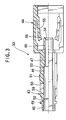
- FIG. 1 is an enlarged view of an optical attenuator 31 according to an embodiment of the present invention, illustrating an upper half of the attenuator in cross section.
- the optical attenuator 31 includes a ferrule 2 having an attenuation film or an attenuation fiber provided thereon, a flange 32 affixed to an outer peripheral at the middle portion of the ferrule 2, a split sleeve 4, a plug frame 33 for supporting the ferrule 2 on which the flange 32 and the split sleeve 4 are affixed, and a housing member 7.
- Fig. 2 is an enlarged view showing the flange 32 partially in cross section.
- the flange 32 is made of plastic material in the form of a cylinder having the wall thickness greater than that of the split sleeve 4.
- a press-fit portion 34 having the minimum inner diameter is formed in the middle portion of the flange 32.
- the ferrule 2 is press-fitted to this press-fit portion 34.
- the flange 32 further includes a deformable portion 35 positioned near the front end thereof and an adhesion portion 36 positioned near the rear end thereof.
- the deformable portion 35 and the adhesion portion 36 have respective inner diameter greater than that of the outer diameter of the ferrule 2.
- the deformable portion 35 has the predetermined number (two in Fig. 2) of engagement projections 37 formed on the outer surface thereof. Each of the engagement projections 37 has a tapered portion at the rear side.
- the deformable portion 35 further has the predetermined number (for example, four) of axial slits 38 formed in the peripheral wall thereof.
- the axial slit 38 is in the form of a triangle whose acute angled apex is pointed to rear side.
- a front end 39 of the deformable portion 35 has the maximum inner diameter so that there is a tapered surface 40 produced between the front end 39 and the press-fit portion 34.
- the adhesion portion 36 has the predetermined number (two in Fig. 2) of circular adhesive injection holes 41 formed in the peripheral wall thereof.
- An enlarged diameter recess portion 42 is formed on an inner surface of the flange 32 at the rear end thereof.
- Fig. 3 is an enlarged view of the plug frame 33, illustrating an upper half of the plug frame in cross section.
- the plug frame 33 is made of plastic material, for example, and includes a cylindrical holding portion 43 in axial direction and a pair of resiliently deformable portions 44 that extend in cantilevered manner from the rear end portion of the holding portion 43 toward the rear side of the attenuator 31.
- the holding portion 43 is designed to floatingly hold the ferrule 2 having the flange 32 and the split sleeve 4 mounted thereon.
- the holding portion 43 is integral with the resiliently deformable portions 44.
- the holding portion 43 is divided into the following sections depending on the wall thickness: a first thin wall section 45; a middle wall thickness section 46; a thick wall section 47; and a second thin wall section 48.
- a first engagement portion 49 is formed on the outer surface of the first thin wall section 45
- a square engagement hole 50 is formed in the middle wall thickness section 46
- a protrusion 51 is formed on the outer surface near the engagement hole 50.
- the outer surface of the holding portion 43 between the first thin wall section 45 and the middle wall thickness section 46, and the front side of the protrusion 51 are outwardly slanted.
- the inner surface of the holding portion 43 is provided with a first shoulder portion 52 between the first thin wall section 45 and the middle wall thickness section 46, and a second shoulder portion 53 between the middle wall thickness section 46 and the thick wall section 47.
- the inner diameter of the holding portion 43 is reduced stepwise from the first thin wall section 45 toward rear side of the optical attenuator 31.
- An inwardly projecting fall-off prevention portion 54 is formed on the rear end of the second thin wall section 48.
- the fall-off prevention portion 54 has its inner diameter that is smaller than the outer diameter of the split sleeve 4, but greater than the outer diameter of the ferrule 2.
- the length between the second shoulder portion 53 and the fall-off prevention portion 54 is greater than that of the split sleeve 4.
- Each of the pair of resiliently deformable portions 44 includes a resilient arm 55 extending in cantilevered manner from the rear end portion of the deformable portion 44 toward the front side of the attenuator 31.
- the resilient arm 55 is provided with a second inwardly projecting engagement portion 56 at the front end thereof. Because the first engagement portion 49 and the second engagement portion 56 are formed on one and same plug frame 33, it becomes easy to control the length between the first engagement portion 49 and the second engagement portion 56 and to allow improvement in precision of the size.
- the ferrule 2 is press-fit to the flange 32 and is held in the press-fit portion 34 of the flange 32. Then the predetermined amount of adhesive is injected via the adhesive injection hole 41 into the flange 32. The adhesive fills the clearance 57 and reaches the enlarged diameter recess portion 42. Because the enlarged diameter recess portion 42 has the inner diameter that is greater than that of the remaining portion of the adhesion portion 36, there is substantially no possibility that the adhesive that has reached the enlarged diameter recess portion 42 would leak to anywhere at the rear side thereof.
- the ferrule 2 having the flange 32 mounted thereon is inserted into the split sleeve 4.
- the front end surface of the split sleeve 4 abuts the rear end surface of the flange 32 and the rear end portion of the split sleeve 4 backwardly projects beyond the rear end of the ferrule 2.
- a shoulder portion 58 is provided between the flange 32 and the split sleeve 4. Because of no possibility that the adhesive would be leaked from the rear end of the flange 32, as described above, the split sleeve 4 intimately abuts the flange 32 without any clearance therebetween. Accordingly the fixed length can always be assured between the front end surface of the flange 32 and the rear end surface of the split sleeve 4, which allows improvement in precision of size of the product.
- the ferrule 2 having the flange 32 and the split sleeve 4 mounted thereon is inserted into the holding portion 43 of the plug frame 33 from the front side thereof, as described earlier.
- the engagement projection 37 of the flange 32 has the tapered outer surface formed at the rear side thereof, and therefore, it is smoothly slid along the inner surface of the first thin wall section 45 of the plug frame 33 to apply a radial and inward force to the deformable portion 35. Because there is the clearance 60 present between the deformable portion 35 and the ferrule 2, and the predetermined number of the slits 38 formed in the flange 32, the deformable portion 38 is gradually reduced in diameter.
- the engagement projection 37 abuts the inner surface of the middle wall thickness section 46, after passing through the first shoulder portion 52. Because the middle wall thickness section 46 has its inner diameter that is smaller than that of the first thin wall section 45, the deformable portion 35 is further reduced in diameter. Thereafter, the engagement projection 37 snaps into the engagement hole 50 and the deformable portion 35 restores the original condition where it was before insertion. Now, the ferrule 2 having the flange 32 and the split sleeve 4 mounted thereon is floatingly supported in the holding portion 43 of the plug frame 33.
- any movement of the ferrule 2 in the direction toward the front side is restricted due to the abutment between the front end surface of the engagement projection 37 and a front side surface 59 of the engagement hole 50.
- any movement of the ferrule 2 in the opposite direction toward the rear side is restricted due to the abutment between the shoulder portion 58 and the second shoulder portion 53 because of the length between the second shoulder portion 53 and the fall-off prevention means 54 greater than that of the split sleeve 4.
- the length therebetween, or in other word, an extent of floating movement can easily be controlled, and consequently, improvement in precision of size can be attained. Furthermore, there is substantially no possibility that the split sleeve 4 is broken or damaged when it is collided to the fall-off prevention means 54.
- the plug frame 33 having the ferrule 2 contained therein is inserted into the housing member 7 from the rear side thereof.
- the first engagement portion 49 and the protrusion 51 are received in the opening 24 so that the plug frame 33 is axially floatingly supported in the housing member 7.
- the optical attenuator has been described by way of an example.
- the present invention is not limited to such optical attenuator, but may applied to any other optical connector components such as a filter, a terminator, etc.
- the flange 32 and the plug frame 33 may include any other mutual engagement portion than that described above.
- the engagement projection 37 may be formed on the plug frame 33 and the engagement hole 50 may be formed in the flange 32.
- the present invention may be configured in such manner that the ferrule 2 having the flange 32 mounted thereon is inserted into the plug frame 33 from the rear side thereof.
- the flange 32 may be formed in which the deformable portion 35 is positioned at the rear side to the press-fit portion 34 and the adhesion portion 36 is positioned at the front side to the press-fit portion 34.
- a plug frame is configured as a one-piece component, a flange is made of resin material and has an engagement portion formed thereon, and a ferrule is held in the plug frame simply by inserting the ferrule having the flange mounted thereon into the plug frame from one side thereof. Therefore, it is possible to reduce the number of component parts and assembling steps, to simplify the assembling operations and to reduce the manufacturing cost.
Landscapes
- Physics & Mathematics (AREA)
- General Physics & Mathematics (AREA)
- Optics & Photonics (AREA)
- Mechanical Coupling Of Light Guides (AREA)
- Optical Couplings Of Light Guides (AREA)
Abstract
Description
Claims (4)
- An optical connector component comprising a ferrule 2 for receiving an end portion of a core optical fiber of a fiber optic cable, a flange 32 mounted on the peripheral of the ferrule 2, and a one-piece plug frame 33 for floatingly supporting the ferrule 2 having the flange 32 mounted thereon, a ferrule holding structure comprising the flange 32 and the plug frame 33, characterized in that:the flange 32 and the plug frame 33 are provided with respective engagement portions 37,50 that are mutually engaged; andthe flange has such resiliency that it is reduced in diameter by a radial and inward force exerted through the engagement portions 37,50 when the ferrule 2 is inserted into the plug frame 33 from one end thereof and the flange 32 is restored to the original condition present before the insertion when the engagement portions 37,50 are mutually engaged.
- A ferrule holding structure according to Claim 1 in which the flange 32 is provided with an adhesive injection hole 41 in the peripheral wall thereof and an enlarged diameter recess portion 42 at one end thereof, and when an adhesive is injected into the adhesive injection hole 41 after the flange 32 is mounted on the ferrule 2, then the adhesive flows between the flange 32 and the ferrule 2 and reaches the enlarged diameter recess portion 42.
- A ferrule holding structure according to Claim 1 or 2 in which a clearance 60 is produced between the flange 32 and the ferrule 2, and when the ferrule 2 having the flange 32 mounted thereon is inserted into the plug frame 33 from one end thereof, the flange 32 is reduced in diameter due to the presence of the clearance.
- A ferrule holding structure according to any one of Claims 1 to 3 in which the flange 32 is made of resin material.
Applications Claiming Priority (2)
| Application Number | Priority Date | Filing Date | Title |
|---|---|---|---|
| JP2001058285 | 2001-03-02 | ||
| JP2001058285A JP3513114B2 (en) | 2001-03-02 | 2001-03-02 | Ferrule holding structure |
Publications (3)
| Publication Number | Publication Date |
|---|---|
| EP1237023A2 true EP1237023A2 (en) | 2002-09-04 |
| EP1237023A3 EP1237023A3 (en) | 2002-11-13 |
| EP1237023B1 EP1237023B1 (en) | 2005-12-14 |
Family
ID=18918031
Family Applications (1)
| Application Number | Title | Priority Date | Filing Date |
|---|---|---|---|
| EP02004349A Expired - Lifetime EP1237023B1 (en) | 2001-03-02 | 2002-03-01 | Ferrule holding structure for optical connector component |
Country Status (6)
| Country | Link |
|---|---|
| US (1) | US6599027B2 (en) |
| EP (1) | EP1237023B1 (en) |
| JP (1) | JP3513114B2 (en) |
| KR (1) | KR100470244B1 (en) |
| CN (1) | CN1189771C (en) |
| DE (1) | DE60207918T2 (en) |
Cited By (1)
| Publication number | Priority date | Publication date | Assignee | Title |
|---|---|---|---|---|
| WO2008005042A1 (en) * | 2006-06-30 | 2008-01-10 | Molex Incorporated | Power limiting optical device |
Families Citing this family (38)
| Publication number | Priority date | Publication date | Assignee | Title |
|---|---|---|---|---|
| TW388100B (en) * | 1997-02-18 | 2000-04-21 | Hitachi Ulsi Eng Corp | Semiconductor deivce and process for producing the same |
| JP3955404B2 (en) * | 1998-12-28 | 2007-08-08 | 株式会社ルネサステクノロジ | Manufacturing method of semiconductor integrated circuit device |
| AU2002354161A1 (en) * | 2002-12-10 | 2004-06-30 | Croster Industry Co., Ltd. | Ferrule and method of manufacturing the ferrule |
| JP4056941B2 (en) * | 2003-06-17 | 2008-03-05 | Smk株式会社 | Optical fixed attenuator and manufacturing method thereof |
| JP4058394B2 (en) * | 2003-07-10 | 2008-03-05 | シャープ株式会社 | Optical connector receptacle, optical connector, and electronic device |
| JP4789543B2 (en) * | 2005-08-18 | 2011-10-12 | 株式会社日立製作所 | Optical transmission device having a pluggable variable optical attenuator |
| KR100796268B1 (en) | 2006-06-02 | 2008-01-21 | 주식회사 제씨콤 | Ferrule-Flange Fixing Jig of Optical Communication Connector and Adhesive Resin Filling Method Using The Same |
| KR100821292B1 (en) * | 2006-11-28 | 2008-04-11 | 주식회사 제씨콤 | Glass Ferrules with Flat Surfaces |
| US7563034B2 (en) * | 2007-09-21 | 2009-07-21 | Opnext, Inc. | Anti-wiggle optical receptacle |
| US8236297B2 (en) * | 2007-10-11 | 2012-08-07 | Kenneth Manzo | Method of treating lactose intolerance using genetically engineered bacteria |
| JP5182893B2 (en) * | 2009-11-17 | 2013-04-17 | Nttエレクトロニクス株式会社 | Optical connector plug |
| JP6496611B2 (en) * | 2015-06-05 | 2019-04-03 | 三和電気工業株式会社 | Boots for optical connector ferrules |
| JP6649065B2 (en) | 2015-12-04 | 2020-02-19 | 三和電気工業株式会社 | Boots for optical connector ferrule |
| US10187175B2 (en) * | 2016-11-18 | 2019-01-22 | Kohoku Kogyo Co., Ltd. | Optical multiplexer/demultiplexer and optical transceiver |
| CN108802910A (en) * | 2017-04-28 | 2018-11-13 | 中天海洋系统有限公司 | Optical connector |
| US11668890B2 (en) | 2017-06-28 | 2023-06-06 | Corning Research & Development Corporation | Multiports and other devices having optical connection ports with securing features and methods of making the same |
| US11187859B2 (en) | 2017-06-28 | 2021-11-30 | Corning Research & Development Corporation | Fiber optic connectors and methods of making the same |
| CN111065946B (en) | 2017-06-28 | 2023-08-18 | 康宁研究与开发公司 | Multiport and other devices having keyed connection ports and securing features and methods of manufacture |
| US12271040B2 (en) | 2017-06-28 | 2025-04-08 | Corning Research & Development Corporation | Fiber optic extender ports, assemblies and methods of making the same |
| US10359577B2 (en) | 2017-06-28 | 2019-07-23 | Corning Research & Development Corporation | Multiports and optical connectors with rotationally discrete locking and keying features |
| US11300746B2 (en) | 2017-06-28 | 2022-04-12 | Corning Research & Development Corporation | Fiber optic port module inserts, assemblies and methods of making the same |
| US12571977B2 (en) | 2017-06-28 | 2026-03-10 | Corning Research & Development Corporation | Multiports and other devices having optical connection ports with securing features and methods of making the same |
| JP7027781B2 (en) * | 2017-10-04 | 2022-03-02 | 住友電気工業株式会社 | Optical connector and optical connection structure |
| EP3887883B1 (en) | 2018-11-29 | 2023-11-08 | Corning Research & Development Corporation | Multiport having connection ports with rotating actuators |
| MX2021014427A (en) | 2019-05-31 | 2022-03-04 | Corning Res & Dev Corp | MULTIPORTS AND OTHER DEVICES THAT HAVE OPTICAL CONNECTION PORTS WITH SLIDING ACTUATORS AND METHODS FOR MAKING SAME. |
| US11294133B2 (en) | 2019-07-31 | 2022-04-05 | Corning Research & Development Corporation | Fiber optic networks using multiports and cable assemblies with cable-to-connector orientation |
| EP3805827B1 (en) | 2019-10-07 | 2025-07-30 | Corning Research & Development Corporation | Fiber optic terminals and fiber optic networks having variable ratio couplers |
| WO2021076325A1 (en) | 2019-10-18 | 2021-04-22 | Corning Research & Development Corporation | Terminals having optical connection ports with securing features providing stable retention forces and methods of making the same |
| US11650388B2 (en) | 2019-11-14 | 2023-05-16 | Corning Research & Development Corporation | Fiber optic networks having a self-supporting optical terminal and methods of installing the optical terminal |
| US11536921B2 (en) | 2020-02-11 | 2022-12-27 | Corning Research & Development Corporation | Fiber optic terminals having one or more loopback assemblies |
| EP4172671B1 (en) | 2020-06-29 | 2026-01-21 | Corning Research & Development Corporation | Terminals having a multi-fiber optical connection port that inhibits damage from single-fiber connectors |
| US11604320B2 (en) | 2020-09-30 | 2023-03-14 | Corning Research & Development Corporation | Connector assemblies for telecommunication enclosures |
| PL4237889T3 (en) | 2020-10-30 | 2026-01-26 | Corning Research & Development Corporation | FEMALE FIBER OPTIC CONNECTORS WITH LOCKING ARM WITH ROCKING MECHANISM |
| US11994722B2 (en) | 2020-11-30 | 2024-05-28 | Corning Research & Development Corporation | Fiber optic adapter assemblies including an adapter housing and a locking housing |
| US11880076B2 (en) | 2020-11-30 | 2024-01-23 | Corning Research & Development Corporation | Fiber optic adapter assemblies including a conversion housing and a release housing |
| US11927810B2 (en) | 2020-11-30 | 2024-03-12 | Corning Research & Development Corporation | Fiber optic adapter assemblies including a conversion housing and a release member |
| US11686913B2 (en) | 2020-11-30 | 2023-06-27 | Corning Research & Development Corporation | Fiber optic cable assemblies and connector assemblies having a crimp ring and crimp body and methods of fabricating the same |
| US11947167B2 (en) | 2021-05-26 | 2024-04-02 | Corning Research & Development Corporation | Fiber optic terminals and tools and methods for adjusting a split ratio of a fiber optic terminal |
Family Cites Families (17)
| Publication number | Priority date | Publication date | Assignee | Title |
|---|---|---|---|---|
| JPS5799605A (en) * | 1980-12-12 | 1982-06-21 | Nec Corp | Optical connector |
| US4812006A (en) * | 1983-11-23 | 1989-03-14 | Amphenol Corporation | Fiber optic connector with colley retention |
| JP3161609B2 (en) * | 1991-08-14 | 2001-04-25 | 日本電信電話株式会社 | Optical connector plug structure |
| JPH0545924A (en) | 1991-08-19 | 1993-02-26 | Mitsubishi Kasei Corp | Electrostatic charge image developing toner |
| GB9307488D0 (en) * | 1993-04-08 | 1993-06-02 | Amp Holland | Optical fibre connector latching mechanism |
| US5436995A (en) * | 1993-05-14 | 1995-07-25 | Nippon Telegraph And Telephone Corporation | Optical fiber connector unit and optical fiber connector |
| US5373573A (en) * | 1993-06-21 | 1994-12-13 | Itt Corporation | High density fiber optic connector |
| US5394497A (en) * | 1994-02-22 | 1995-02-28 | The Whitaker Corporation | Captivated fiber optic connector |
| JPH08184727A (en) * | 1994-12-28 | 1996-07-16 | Kyocera Corp | Optical connector |
| JP3317824B2 (en) * | 1995-08-25 | 2002-08-26 | 株式会社精工技研 | Manufacturing method of optical attenuation fiber assembly and optical attenuation fiber assembly |
| JP3356373B2 (en) * | 1996-07-26 | 2002-12-16 | 日本電信電話株式会社 | Optical attenuator |
| JPH10170762A (en) * | 1996-12-06 | 1998-06-26 | Molex Inc | Optical fiber cable holding mechanism of optical connector |
| JP3370908B2 (en) * | 1997-08-18 | 2003-01-27 | 株式会社フジクラ | Optical connector |
| JPH11160544A (en) * | 1997-11-28 | 1999-06-18 | Kyocera Corp | Optical attenuator and method of manufacturing the same |
| FR2787890B1 (en) * | 1998-12-24 | 2002-01-04 | Radiall Sa | OPTICAL CONNECTOR ELEMENT WITH MONOBLOCK BODY |
| JP3825930B2 (en) * | 1999-01-28 | 2006-09-27 | ヒロセ電機株式会社 | Optical connector |
| JP3398617B2 (en) * | 1999-04-09 | 2003-04-21 | セイコーインスツルメンツ株式会社 | Adhesive injection tube |
-
2001
- 2001-03-02 JP JP2001058285A patent/JP3513114B2/en not_active Expired - Lifetime
-
2002
- 2002-02-27 KR KR10-2002-0010493A patent/KR100470244B1/en not_active Expired - Fee Related
- 2002-02-28 CN CNB021064407A patent/CN1189771C/en not_active Expired - Fee Related
- 2002-03-01 DE DE60207918T patent/DE60207918T2/en not_active Expired - Fee Related
- 2002-03-01 EP EP02004349A patent/EP1237023B1/en not_active Expired - Lifetime
- 2002-03-01 US US10/086,593 patent/US6599027B2/en not_active Expired - Fee Related
Cited By (1)
| Publication number | Priority date | Publication date | Assignee | Title |
|---|---|---|---|---|
| WO2008005042A1 (en) * | 2006-06-30 | 2008-01-10 | Molex Incorporated | Power limiting optical device |
Also Published As
| Publication number | Publication date |
|---|---|
| DE60207918D1 (en) | 2006-01-19 |
| EP1237023A3 (en) | 2002-11-13 |
| US6599027B2 (en) | 2003-07-29 |
| CN1374540A (en) | 2002-10-16 |
| JP2002258104A (en) | 2002-09-11 |
| EP1237023B1 (en) | 2005-12-14 |
| KR20020070830A (en) | 2002-09-11 |
| JP3513114B2 (en) | 2004-03-31 |
| DE60207918T2 (en) | 2006-10-26 |
| US20020122634A1 (en) | 2002-09-05 |
| CN1189771C (en) | 2005-02-16 |
| KR100470244B1 (en) | 2005-02-05 |
Similar Documents
| Publication | Publication Date | Title |
|---|---|---|
| US6599027B2 (en) | Ferrule holding structure for optical connector component | |
| AU685710B2 (en) | Optical fiber connector plug and optical fiber connector | |
| US4553814A (en) | Detachable fiber optic connector assembly | |
| US4208092A (en) | Fiber optic multi-cable pair connector | |
| KR100204370B1 (en) | Duplex connector | |
| US5499310A (en) | Optical fiber connector with sleeve for resiliently fitting an optical fiber thereto | |
| US6873784B2 (en) | Optical attenuator | |
| JP3226755B2 (en) | Optical fiber connector assembling method and adhesive injection jig | |
| US6474878B1 (en) | Optical connector | |
| KR100307481B1 (en) | Fiber Optic Connector | |
| JP3712958B2 (en) | Optical connector plug | |
| US6776535B2 (en) | One-piece construction of plug frame for optical connector component | |
| EP0281871A2 (en) | Fiber optic device coupling | |
| JP3329436B2 (en) | Optical connector | |
| JPH04235508A (en) | Optical connector | |
| JP2920818B2 (en) | Ferrule for optical connector | |
| JPH1039167A (en) | Ferrule | |
| JP3157558B2 (en) | Ferrule for optical connector | |
| JP3685231B2 (en) | Optical receptacle for optical measurement | |
| JPH11119057A (en) | Optical connector plug | |
| KR100288440B1 (en) | Optical adapter | |
| JP2579871Y2 (en) | Optical connector adapter | |
| JPS5936207A (en) | Optical connector | |
| JP2593042Y2 (en) | Outer member of ferrule for optical connector | |
| JP2003139994A (en) | Optical holder assembling method, optical ferrule press-in method, and optical ferrule receptacle |
Legal Events
| Date | Code | Title | Description |
|---|---|---|---|
| PUAI | Public reference made under article 153(3) epc to a published international application that has entered the european phase |
Free format text: ORIGINAL CODE: 0009012 |
|
| AK | Designated contracting states |
Kind code of ref document: A2 Designated state(s): AT BE CH CY DE DK ES FI FR GB GR IE IT LI LU MC NL PT SE TR |
|
| AX | Request for extension of the european patent |
Free format text: AL;LT;LV;MK;RO;SI |
|
| PUAL | Search report despatched |
Free format text: ORIGINAL CODE: 0009013 |
|
| AK | Designated contracting states |
Kind code of ref document: A3 Designated state(s): AT BE CH CY DE DK ES FI FR GB GR IE IT LI LU MC NL PT SE TR |
|
| AX | Request for extension of the european patent |
Free format text: AL;LT;LV;MK;RO;SI |
|
| RIC1 | Information provided on ipc code assigned before grant |
Free format text: 7G 02B 6/38 A, 7G 02B 6/26 B |
|
| 17P | Request for examination filed |
Effective date: 20030227 |
|
| AKX | Designation fees paid |
Designated state(s): DE FR GB IT |
|
| 17Q | First examination report despatched |
Effective date: 20041019 |
|
| GRAP | Despatch of communication of intention to grant a patent |
Free format text: ORIGINAL CODE: EPIDOSNIGR1 |
|
| GRAS | Grant fee paid |
Free format text: ORIGINAL CODE: EPIDOSNIGR3 |
|
| GRAA | (expected) grant |
Free format text: ORIGINAL CODE: 0009210 |
|
| AK | Designated contracting states |
Kind code of ref document: B1 Designated state(s): DE FR GB IT |
|
| RAP1 | Party data changed (applicant data changed or rights of an application transferred) |
Owner name: NIPPON TELEGRAPH AND TELEPHONE CORPORATION Owner name: HIROSE ELECTRIC CO., LTD. |
|
| REG | Reference to a national code |
Ref country code: GB Ref legal event code: FG4D |
|
| REF | Corresponds to: |
Ref document number: 60207918 Country of ref document: DE Date of ref document: 20060119 Kind code of ref document: P |
|
| ET | Fr: translation filed | ||
| PLBE | No opposition filed within time limit |
Free format text: ORIGINAL CODE: 0009261 |
|
| STAA | Information on the status of an ep patent application or granted ep patent |
Free format text: STATUS: NO OPPOSITION FILED WITHIN TIME LIMIT |
|
| 26N | No opposition filed |
Effective date: 20060915 |
|
| PGFP | Annual fee paid to national office [announced via postgrant information from national office to epo] |
Ref country code: GB Payment date: 20090303 Year of fee payment: 8 |
|
| PGFP | Annual fee paid to national office [announced via postgrant information from national office to epo] |
Ref country code: DE Payment date: 20090326 Year of fee payment: 8 Ref country code: IT Payment date: 20090212 Year of fee payment: 8 |
|
| PGFP | Annual fee paid to national office [announced via postgrant information from national office to epo] |
Ref country code: FR Payment date: 20090123 Year of fee payment: 8 |
|
| GBPC | Gb: european patent ceased through non-payment of renewal fee |
Effective date: 20100301 |
|
| REG | Reference to a national code |
Ref country code: FR Ref legal event code: ST Effective date: 20101130 |
|
| PG25 | Lapsed in a contracting state [announced via postgrant information from national office to epo] |
Ref country code: FR Free format text: LAPSE BECAUSE OF NON-PAYMENT OF DUE FEES Effective date: 20100331 |
|
| PG25 | Lapsed in a contracting state [announced via postgrant information from national office to epo] |
Ref country code: DE Free format text: LAPSE BECAUSE OF NON-PAYMENT OF DUE FEES Effective date: 20101001 |
|
| PG25 | Lapsed in a contracting state [announced via postgrant information from national office to epo] |
Ref country code: IT Free format text: LAPSE BECAUSE OF NON-PAYMENT OF DUE FEES Effective date: 20100301 Ref country code: GB Free format text: LAPSE BECAUSE OF NON-PAYMENT OF DUE FEES Effective date: 20100301 |