EP1236955B1 - Disengagement linkage mechanism of extinction device for burner - Google Patents
Disengagement linkage mechanism of extinction device for burner Download PDFInfo
- Publication number
- EP1236955B1 EP1236955B1 EP02090078A EP02090078A EP1236955B1 EP 1236955 B1 EP1236955 B1 EP 1236955B1 EP 02090078 A EP02090078 A EP 02090078A EP 02090078 A EP02090078 A EP 02090078A EP 1236955 B1 EP1236955 B1 EP 1236955B1
- Authority
- EP
- European Patent Office
- Prior art keywords
- extinction
- spring
- linkage
- shape memory
- burner
- Prior art date
- Legal status (The legal status is an assumption and is not a legal conclusion. Google has not performed a legal analysis and makes no representation as to the accuracy of the status listed.)
- Expired - Lifetime
Links
- 230000008033 biological extinction Effects 0.000 title claims abstract description 113
- 230000007246 mechanism Effects 0.000 title claims description 60
- 230000003213 activating effect Effects 0.000 claims description 44
- 238000002485 combustion reaction Methods 0.000 claims description 35
- 239000011796 hollow space material Substances 0.000 claims description 9
- 230000002093 peripheral effect Effects 0.000 claims description 4
- 238000013459 approach Methods 0.000 claims description 2
- 230000002265 prevention Effects 0.000 claims 1
- 229910001285 shape-memory alloy Inorganic materials 0.000 description 11
- 238000010276 construction Methods 0.000 description 4
- QVGXLLKOCUKJST-UHFFFAOYSA-N atomic oxygen Chemical compound [O] QVGXLLKOCUKJST-UHFFFAOYSA-N 0.000 description 3
- 230000008859 change Effects 0.000 description 3
- 229910052760 oxygen Inorganic materials 0.000 description 3
- 239000001301 oxygen Substances 0.000 description 3
- CURLTUGMZLYLDI-UHFFFAOYSA-N Carbon dioxide Chemical compound O=C=O CURLTUGMZLYLDI-UHFFFAOYSA-N 0.000 description 2
- 230000003247 decreasing effect Effects 0.000 description 2
- 230000006870 function Effects 0.000 description 2
- 101000643890 Homo sapiens Ubiquitin carboxyl-terminal hydrolase 5 Proteins 0.000 description 1
- 102100021017 Ubiquitin carboxyl-terminal hydrolase 5 Human genes 0.000 description 1
- 230000002159 abnormal effect Effects 0.000 description 1
- 230000009471 action Effects 0.000 description 1
- 230000004913 activation Effects 0.000 description 1
- 229910002092 carbon dioxide Inorganic materials 0.000 description 1
- 239000001569 carbon dioxide Substances 0.000 description 1
- 238000007796 conventional method Methods 0.000 description 1
- 230000001419 dependent effect Effects 0.000 description 1
- 230000000694 effects Effects 0.000 description 1
- 230000006872 improvement Effects 0.000 description 1
- 238000004519 manufacturing process Methods 0.000 description 1
- 238000000034 method Methods 0.000 description 1
- 238000012986 modification Methods 0.000 description 1
- 230000004048 modification Effects 0.000 description 1
- 229920003002 synthetic resin Polymers 0.000 description 1
- 239000000057 synthetic resin Substances 0.000 description 1
Images




Classifications
-
- A—HUMAN NECESSITIES
- A62—LIFE-SAVING; FIRE-FIGHTING
- A62C—FIRE-FIGHTING
- A62C37/00—Control of fire-fighting equipment
- A62C37/08—Control of fire-fighting equipment comprising an outlet device containing a sensor, or itself being the sensor, i.e. self-contained sprinklers
- A62C37/10—Releasing means, e.g. electrically released
- A62C37/11—Releasing means, e.g. electrically released heat-sensitive
- A62C37/16—Releasing means, e.g. electrically released heat-sensitive with thermally-expansible links
-
- F—MECHANICAL ENGINEERING; LIGHTING; HEATING; WEAPONS; BLASTING
- F23—COMBUSTION APPARATUS; COMBUSTION PROCESSES
- F23Q—IGNITION; EXTINGUISHING-DEVICES
- F23Q25/00—Extinguishing-devices, e.g. for blowing-out or snuffing candle flames
-
- F—MECHANICAL ENGINEERING; LIGHTING; HEATING; WEAPONS; BLASTING
- F23—COMBUSTION APPARATUS; COMBUSTION PROCESSES
- F23D—BURNERS
- F23D3/00—Burners using capillary action
- F23D3/02—Wick burners
- F23D3/18—Details of wick burners
-
- F—MECHANICAL ENGINEERING; LIGHTING; HEATING; WEAPONS; BLASTING
- F23—COMBUSTION APPARATUS; COMBUSTION PROCESSES
- F23D—BURNERS
- F23D2209/00—Safety arrangements
Definitions
- the present invention relates to an extinguishing device for burners like oil burners, and more particularly to a disengagement linkage mechanism for disengaging an engagement state of an engagement structure in an extinction device using a shape memory coiled spring which has a characteristic to expand when the circumference temperature exceeds over a predetermined level or temperature.
- Figs. 2 and 3 of USP 5,413,479 (corresponding to Japanese Laid-Open Patent Application Publication No. 241449/1994) is shown an example of an extinguishing device for an oil burner having an extinguishing device activated by a vibration sensing device.
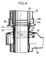
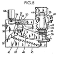
- Figs. 1 - 3 of the USP 5,413,479 are used as Figs. 4 - 6 in the present application.
- This conventional extinguishing device is attached to a frame 45 having a vertical frame portion and a horizontal frame portion.
- the vibration sensing device 54 is provided with a vibration sensing weight 64 which is supported above the horizontal frame portion in a manner to be tilted when vibration is sensed.
- this extinguishing device is provided with an extinction activating arm 30, 38 an energizing spring 62 for energizing the extinction activating arm 30, 38 and a mechanical combustion control mechanism 56, 69 attached to the frame.
- the extinction activating arm has two ends, one and the other end. The one end of the extinction activating arm is rotatably mounted on the vertical frame portion and the extinction activating arm moves or swings along the vertical frame portion.
- the extinction activating arm is provided at positions thereof which are apart from the one end toward the other end with an engaged portion 52 and a holding portion at which a part of vibration sensing weight 64 is held.When vibration is sensed and the vibration sensing weight 64 is tilted, the extinction activating arm is turned upward with the one end of the arm as the center of the rotation.
- the energizing spring 62 gives a force to the extinction activating arm to rotate downward with the one end as the center of the rotation.
- the mechanical combustion control mechanism has a rotation plate 46 having an engaging portion 56 which engages with the engaged portion 52 of the extinction actuating arm.
- the combustion portion of the oil burner is kept in a condition in which combustion can be carried out (the wick 26 is kept at a position at which the combustion of the wick is possible).
- the vibration sensing weight 64 of the vibration sensing device is tilted and the extinction activating arm rotates upward with the one end as the center of rotation and the engaging portion 56 and the engaged portion 52 are disengaged, the rotation plate 46 turns to put the combustion portion in a condition that the combustion is not possible (the wick 26 is lowered to the position at which combustion is not possible).
- Fig. 1 of the Japanese Patent Application Laid - Open Publication No. 329345/2000 is used as Fig. 7 in the present application.
- a shape memory coiled spring I 1 is used as the temperature sensor.
- a disengagement linkage mechanism for disengaging the engagement portions used in the extinction device in the art comprises a swinging linkage 9 held free to swing around the rotation center 9a, a shape memory coiled spring 11 arranged between the swinging linkage 9 and the frame for generating a spring force to swing the swinging linkage 9 in one direction around the rotation center 9a and a bias spring 10 arranged between the swinging linkage 9 and the frame for generating a spring force to swing the swinging linkage 9 in the other direction around the rotation center 9a.
- the shape memory coiled spring 11 in the art contracts when the circumference temperature exceeds a predetermined level or temperature, and generates a torque which is larger than a torque generated by the spring force of bias spring 10 which is given to the swinging linkage 9.
- this prior mechanism is provided with a disengagement linkage mechanism 8, 12.
- a swinging linkage 9 stays in a position to permit the extinction activating arm 6 to move freely before the circumference temperature exceeds a predetermined level.
- the swinging linkage 9, engages with the extinction activating arm 6 and swings up to such a postion that the extinction activating arm 6 may be turned upward around at one end 6a thereof to disengae the engagement between the engaging portion and the engaged portion, when the circumference temperature exceeds the predetermined level.
- the shape memory coiled spring which is used as the temperature sensor has hooks at both ends thereof.
- the precision in the extinction operation of the conventional extinction device depends on the precision of the operation of the shape memory coiled spring. In the conventional structure, however, the variance in the starting temperature for the extinction operation has been considerable and the precision of the extinction operation could not have been enhanced.
- JP05248611A shows an automatic temperature adjusting mechanism for adjusting automatically adjusting firepower of an oil burner so that the room temperature should be maintained at a constant level.
- this mechanism an ordinary spring and a shape memory alloy spring are juxtaposedly arranged between a driving plate and a connecting plate.
- the shape memory alloy spring contracts, demonstrating stronger contracting force than the spring force of the ordinary spring when the room temperature exceeds a specified value. As a result, the firepower is adjusted to be minimized when the room temperature becomes high.
- This prior art does not disclose that a shape memory alloy spring is used with an extinguisher.
- JP60050313A shows a construction comprising a first shape memory alloy spring which is used for shifting an extinguishing lever when extinguishing the fire and a second shape memory alloy spring which is used for restoring the lever.
- a circuit for supplying current is provided for each of these shape memory alloy springs.
- the first and the second shape memory alloy springs are heated when current is supplied, and then they change in shape.
- the first shape memory alloy spring also changes in shape when the temperature increases in case of abnormal combustion.
- current is supplied to the first shape memory alloy spring which accordingly changes in shape. Then, the extinguishing lever is driven to start fire extinguishing.
- the construction disclosed in this prior art essentially comprises two shape memory alloy springs, two circuits for supplying current to the springs respectively, and the extinguishing lever.
- the construction according to this prior art is complicated and the number of elements of the construction is large, which leads to an increased price of the burner.
- the present invention has been made in view of the foregoing disadvantage of the prior art. Accordingly, it is an object of the present invention to provide a disengagement linkage mechanism of an extinction device for a burner in which the precision of the extinction device can be heightened or enhanced even when a shape memory coiled spring is used as the temperature sensor.
- the present invention relates to an improvement of the disengagement linkage mechanism of an extinction device for a burner which activates the extinction operation by disengaging the engagement state of the engagement structure in the extinction device, when the temperature of a surrounding place exceeds a predetermined level or temperature.
- the disengagement linkage mechanism comprises a swinging link plate or a swinging linkage which is rotatably held and swings around the center when disengaging the engagement state of the engagement structure, a shape memory coiled spring arranged, in a compressed condition, between the swinging linkage and a first fixed portion to generate a spring force to swing, in one direction, the swinging linkage around the rotation center, and a bias spring arranged, in an expanded condition, between the swinging linkage and a second fixed portion to generate a spring force to swing, in the other direction, the swinging linkage around the rotation center.
- the shape memory coiled spring has a characteristic or capacity to generate, by expanding itself, and give, to the swinging linkage, a torque larger than a torque given by a spring force of the bias spring, when the circumference temperature exceeds a predetermined level.
- the shape memory coiled spring with a characteristic to expand when the circumference temperature exceeds a predetermined level has a smaller hysteresis in comparison with a shape memory coiled spring with a characteristic to contract when the circumference temperature exceeds a predetermined level.
- the former shape memory coiled spring has a characteristic that the variance in the temperature at which the expansion starts is small. Therefore the extinction device using the present invention can attain a stable and precise operation as the variance in the temperature for starting the extinction operation is small.
- the direct distance L1 between the point of application of a spring force of the shape memory coiled spring to the swinging linkage and the rotation center is preferably made longer than the direct distance L2 between the point of application of the spring force of the bias spring to the swinging linkage and the rotation center.
- the expansion amount of the bias spring can be smaller than the expansion amount of the shape memory coiled spring. This makes the change of the spring pressure of the bias spring small and thus the variance in the operation of the shape memory coiled spring can be small.
- the attachment structure for attaching the shape memory coiled spring between the swinging linkage and the first fixed portion can be arbitrary.
- the attachment structure may comprise a first base provided on the swinging linkage, a second base provided on the first fixed portion to be opposite to the first base, and a plunger having a pillar which passes through a hollow space of the shape memory coiled spring and being attached to the first and second bases in a manner to permit the shape memory coiled spring to contract or expand between the first and second bases along the pillar.
- This kind of plunger can do away with hooks at both ends of the shape memory coiled spring for attaching the shape memory coiled spring to a predetermined position.
- the hooks are provided at both ends of the shape memory coiled spring, the presence of the hooks themselves is a cause of the error in sensing the starting temperature for starting the extinction operation (the temperature at which the shape memory coiled spring starts expansion).
- the starting temperature for starting the extinction operation the temperature at which the shape memory coiled spring starts expansion.
- the plunger as described above it is not necessary to provide hooks at both ends of the shape memory coiled spring, and the error in sensing the starting temperature can be small and the precision of extinction operation can be heightened.
- the plunger having a first flange and a second flange at both ends of the pillar.
- One of the first and the second bases is formed with a through hole through which the pillar passes, and a first flange is provided at one end of the pillar which passes through the through hole formed either on the first base or the second base.
- a second flange is provided at the other end of the pillar which is positioned between the first and the second bases. The second flange is engaged with the other of the first and the second bases.
- the shape memory coiled spring is arranged between one of the first and the second bases and the second flange in a compressed condition and with the pillar of the plunger disposed in the hollow space thereof. In such an arrangement it is possible to arrange a shape memory coiled spring without hooks in an assuredly operational condition. In addition, it is possible to enable the shape memory coiled spring to contract and expand in a stable and smooth manner.
- One end of the pillar may have a plurality of legs which are arranged in the peripheral direction with some interval therebetween.
- the plural legs may be integrally formed with a plurality of hooks respectively so that the first flange may be constituted by such plurality of hooks at the edge of the legs.
- the second flange may be integrally provided with a projection at the central part of the outside surface thereof and the other of the first and the second bases is formed with a receiving hole for receiving the projection. By fitting the projection in the receiving hole the second flange is engaged with the other of the first and the second bases. With such an arrangement attaching the second flange is easy.
- the center of the pillar is defined with a passage which is open toward one end of the pillar, and the circumferential wall of the pillar is formed with more than one through holes which communicate the passage and the hollow space inside the shape memory coiled spring.
- the passage and the through holes make the difference between the temperature in the space between the pillar and the shape memory coiled spring and the temperature of the space outside the coiled spring small. As a result the variance in the sensing of the predetermined temperature for starting the operation by the shape memory coiled spring is small. Therefore, the variance in the precision of the extinction operation becomes small.
- the disengagement linkage mechanism in the present invention may be used for various kinds of burners. Especially, when the present invention is used for an oil burner, it will contribute to improving the capacity of the extinction device of the oil burner and to decreasing the costs.
- the second flange may be integrally formed with a fitted portion in which one end of the shape memory coiled spring fits.
- the external dimension of the portion of the pillar at which the pillar passes through the through hole and the external dimension of another portion of the pillar extending further therefrom are made slightly smaller than the dimension of the diameter of the through hole.
- the internal dimension of the shape memory coiled spring is made slightly larger than the dimension of the diameter of the through hole. In this instance the shape memory coiled spring can contract and expand in a stable manner without deformation.
- the bias spring is attached in the following manner.
- a hook at one end of the bias spring is engaged by inserting a part of the hook into an engagement hole formed on the swinging linkage.
- the hook at the other end of the bias spring is engaged by inserting a part of the hook into an engagement hole formed on the second fixed portion.
- at least one of the swinging linkage and the frame is formed with a plurality of engagement holes with some interval therebetween.
- Fig. 1 is a front elevation view of an embodiment of the present invention in which the present invention is applied to an extinction device of an oil burner.
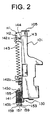
- Fig. 2 is the right side elevation view of the extinction device shown in Fig. 1.
- a vibration sensing weight which will be described later, is omitted from Fig. 2.
- This extinction device is used for such oil burners as shown in USP5, 413,479.
- the frame 101 consists of a vertical frame portion 103 which extends in the vertical direction and a horizontal frame portion 105 which extends in the horizontal direction from the upper end of the vertical frame portion 103.
- the frame 101 is formed by press forming.
- a vibration sensing means 107 has a vibration sensing weight 109 which is placed above the horizontal frame portion 105.
- the vibration sensing means 107 comprises a connecting pole 111 having an upper end and a lower end which loosely passes through the horizontal frame portion 105, a coming-off preventing portion 113 fixed at the lower end of the connecting pole 111, and the vibration sensing weight 109 fixed at the upper end of the connecting pole 111 and supported above the horizontal frame portion 105.
- the connecting pole 111 of the vibration sensing means 107 is engaged with an extinction activating arm 115.
- the extinction activating arm 115 has an end and the other end, and the one end is rotatably fixed to a shaft 117 which is provided on the vertical frame portion 103.
- the extinction activating arm 115 moves along the vertical frame portion 103.
- the extinction activating arm 115 is formed, at a position apart from the one end toward the other end thereof, with a pin 119 constituting an engaged portion, and further toward the other end, is also formed with a through hole 121 which permits the connecting pole 111 of the vibration sensing weight 109 to pass therethrough loosely but prevents the comlng-off preventing portion 113 from passing therethrough.
- An energizing spring 123 is arranged between the extinction activating arm 115 and the horizontal frame portion 105.
- the energizing spring 123 gives a force to the extinction activating arm 115 to move downward around the shaft 117,
- the extinction activating arm 115 is made of synthetic resin and is formed with the energizing spring 123 which constitutes a part of the extinction activating arm 115.
- a mechanical combustion control mechanism 125 is attached behind the vertical frame portion 103.
- the combustion control mechanism 125 comprises a rotation plate 129 having a recess 127 which constitutes an engaging portion for engaging with the above described engaged portion constituted by the pin 119.
- This rotation plate 129 rotates around the rotation center 131.
- a revolving lever (shown at reference numeral 130) revolves around the revolution center to raise the combustion cylinder (not shown) at the ignition and returns to the original place after the ignition is carried out.
- a first operation knob 132 is fixed at one end of the revolving lever 130. When a force applied to the first operation knob is released, the revolving lever 130 returns to the original condition due to the spring force of a return spring 128.
- the first operation knob 132 and a second operation knob 134 which will be described later are respectively mounted on a sliding garter 104 formed at the vertical frame portion 103. The operation knobs 132 and 134 move upwardly and downwardly along the sliding garter 104.
- An operating lever 133 is rotatably attached to the vertical frame portion 103 in a manner to move around the rotation center 131.
- a wick operating shaft (not shown) for moving the wick upward and downward is rotated and the wick for combustion is raised or pulled down.
- the wick is kept in an upper position, the combustion of the oil burner is possible and when the wick is kept in the lowest position, the oil burner is in the extinction condition.
- the engagement relation between the operating lever 133 and the rotation plate 129 is already known and is described in USP 5,413,479.
- the function of a return spring 135 attached to the rotation plate 129 is also already known and is described in detail in USP 5,413,479 and the Japanese Patent Application Laid-Open Publication No.
- the mechanical combustion control mechanism 125 keeps the wick of the oil burner at a position which permits the combustion is possible, when the engaging portion (recess) 127 is engaged with the engaged portion (pin) 119 after an operation force is applied to the operating lever 133 from the operating knob 134.
- the front side of the vertical frame portion 103 (the opposite side against the side where the combustion control mechanism 125 is attached) is provided with a disengagement linkage mechanism 137.
- the disengagement linkage mechanism disengages the engagement state between the engaging portion (recess) 127 and the engaged portion (pin) 119 to carry out the extinction when the circumference temperature reaches a predetermined level.
- the content of the present invention lies in the configuration of this disengagement linkage mechanism 137.
- the disengagement linkage mechanism 137 permits the extinction activating arm 115 to move freely when the circumference temperature is below a predetermined level.
- the disengagement linkage mechanism 137 moves the extinction activating arm 115 upward around the revolving shaft 117 to disengage the engagement state between the recess (engaging portion) 127 and the pin (engaged portion) 119 when the circumference temperature reaches the predetermined temperature.
- the predetermined temperature is determined so that incomplete combustion may be avoided based on the presupposed relation between the temperature and the concentration of oxygen or carbon dioxide in the air.
- the disengagement link mechanism 137 comprises a swinging linkage 139, a shape memory coiled spring 141 and a bias spring 143.
- the swinging linkage 139 having a lifting portion 140 for lifting the extinction activating arm 115 upward is arranged to move around the rotation center 145.
- the centerline of the rotation center 145 extends perpendicularly to the plate of the vertical frame portion 103.
- the swinging linkage 139 is also provided with an abutting portion 149.
- the abutting portion 149 abuts a revolving lever 147 which is moved clockwise by the operating knob 134 when the operating lever 133 is pushed downward.
- the abutting portion 149 then moves the swinging linkage 139 around the rotation center 145 counterclockwise.
- the revolving lever 147 is arranged to be able to revolve freely around another revolving center 148 which is provided on the vertical frame portion 103.
- the revolving lever 147 and the abutting portion 149 constitute a pressure applying link mechanism.
- the pressure applying link mechanism is driven by an operational force applied from the outside of the combustion control mechanism 125 in order to swing the swinging linkage 139 in a direction to compress the shape memory coiled spring 141.
- the swinging linkage is not prevented from moving freely after the operational force is discharged or removed.
- the shape memory coiled spring 141 is arranged between the swinging linkage 139 and the frame 101.
- the shape memory coiled spring 141 generates a spring force, by expanding when the circumference temperature exceeds a predetermined level, to rotate the swinging linkage 139 in a direction in which the lifting portion thereof approaches the extinction activating arm 115.
- the bias spring 143 is arranged between the swinging linkage 139 and the frame 101 and generates a spring force to rotate the swinging linkage 139 in a direction in which the lifting portion thereof moves away from the extinction activating arm 115.
- the shape memory coiled spring has a characteristic to expand, when the circumference temperature exceeds a predetermined level, and to give, to the swinging linkage 139, a torque larger than a torque given by a spring force of the bias spring 143.
- the attachment structure of the shape memory coiled spring 141 comprises a first base 145a formed on the swinging linkage 139, a second base 145b (the first fixed portion) which is disposed at the lower end of the vertical frame portion 103 to be opposite to the first base 145a, and a plunger 150.
- the plunger 150 has a structure comprising a pillar 151 and a first flange 153 and a second flange 155 fixed at both ends of the pillar 151.
- the second base 145b is formed with a through hole 145c through which the pillar 151 passes.
- the first flange 153 is fixed at one end of the pillar 151 which passes through the through hole 145c and projects to the outside of the second base 145b. Also the second flange 155 is fixed at the other end of the pillar 151 which is disposed between the first base 145a and the second base 145b and is connected with the first base 145a.
- the shape memory coiled spring 141 is arranged between the second base 145 and the second flange 155 in a compressed manner with the pillar 151 disposed in the hollow space thereof.
- a part of the pillar 151 at one end comprises a plurality of legs formed in the peripheral direction with some interval therebetween defined with slits 157.
- the slits 157 are open toward the central space 142.
- the pillar 151 is formed with a through hole 152 which communicates the inner passage defined inside the pillar 151 and the hollow space inside the coiled spring.
- the plural legs are integrally provided respectively at the edge thereof with hooks which constitute the first flange 153.
- the second flange 155 is provided with a projection 156 at the center of the outside surface thereof.
- the first base 145a is formed with a hole into which the projection 156 is fitted.
- the second flange 155 is integrally formed with a fitted portion at which one end of the shape memory coiled spring fits.
- the external dimension of the part of the pillar 151 at which the pillar passes through the through hole 148 and the external dimension of the part of the pillar further extending therefrom are slightly smaller than the dimension of the through hole 148, and the internal dimension of the shape memory coiled spring 141 is slightly larger the dimension of the diameter of the through hole 148.
- the bias spring 143 is provided at both ends thereof with hooks 142a and 142b.
- the hook 142b at one end of the bias spring 143 is engaged with the swinging linkage by inserting a part of the hook 142b into the hole (not shown) provided on the swinging linkage 139.
- the hook 142a at the other end of the bias spring 143 is engaged with the second fixed portion by inserting a part of the hook 142a into another engagement hole H2 provided on the second fixed portion.
- the second fixed portion 144 has three engagement holes H1-H3 arranged in the vertical direction with certain interval therebetween.
- the through hole 148 is formed on the side of the second base 145b.
- a through hole 148 may, of course, be formed on the side of the first base 145a in which case the plunger 149 is set upside down.
- the direct distance L1 between the point of application of the spring force of the shape memory coiled spring 141 to the swinging linkage 139 and the rotation center 145 is longer than the direct distance L2 between the point of application of the bias spring 143 to the swinging linkage 139 and the rotation center 145, therefore the stretch length of the bias spring 143 can be shorter than the stretch length of the shape memory coiled spring. This permits the change of the spring force of the bias spring 143 to be small. As a result the variance in the operation of the shape memory coiled spring can be made smaller.
- the present invention stable and precise operation can be maintained in the extinction operation as the variance in the temperature for starting the extinction operation (precision in the extinction operation) is small because such a spring is used for the shape memory coiled spring as one having a capacity to generate, by expanding itself, and give, to the swinging linkage , a larger torque than a torque given by a spring force of the bias spring, when the circumference temperature exceeds a predetermined level.
- the stretch length of the bias spring can be made shorter in comparison with the stretch length of the shape memory coiled spring.
- the variance in the operation of the shape memory coiled spring can be made smaller.
- the shape memory coiled spring is attached using a plunger, it is unnecessary to form hooks at both ends of the shape memory coiled spring for attaching it to a predetermined position. This contributes to making the variance in the temperature for starting the extinction operation smaller, thus heightening the precision of the extinction operation.
Landscapes
- Engineering & Computer Science (AREA)
- Chemical & Material Sciences (AREA)
- Combustion & Propulsion (AREA)
- Mechanical Engineering (AREA)
- General Engineering & Computer Science (AREA)
- Health & Medical Sciences (AREA)
- Public Health (AREA)
- Business, Economics & Management (AREA)
- Emergency Management (AREA)
- Regulation And Control Of Combustion (AREA)
- Control Of Combustion (AREA)
Abstract
Description
- The present invention relates to an extinguishing device for burners like oil burners, and more particularly to a disengagement linkage mechanism for disengaging an engagement state of an engagement structure in an extinction device using a shape memory coiled spring which has a characteristic to expand when the circumference temperature exceeds over a predetermined level or temperature.
- In Figs. 2 and 3 of USP 5,413,479 (corresponding to Japanese Laid-Open Patent Application Publication No. 241449/1994) is shown an example of an extinguishing device for an oil burner having an extinguishing device activated by a vibration sensing device. Figs. 1 - 3 of the USP 5,413,479 are used as Figs. 4 - 6 in the present application. This conventional extinguishing device is attached to a
frame 45 having a vertical frame portion and a horizontal frame portion. Thevibration sensing device 54 is provided with a vibration sensingweight 64 which is supported above the horizontal frame portion in a manner to be tilted when vibration is sensed. Furthermore this extinguishing device is provided with anextinction activating arm spring 62 for energizing theextinction activating arm combustion control mechanism portion 52 and a holding portion at which a part of vibration sensingweight 64 is held.When vibration is sensed and the vibration sensingweight 64 is tilted, the extinction activating arm is turned upward with the one end of the arm as the center of the rotation. The energizingspring 62 gives a force to the extinction activating arm to rotate downward with the one end as the center of the rotation. The mechanical combustion control mechanism has arotation plate 46 having anengaging portion 56 which engages with the engagedportion 52 of the extinction actuating arm. When an operational force is applied from outside and theengaging portion 56 of therotational plate 46 engages with the engagedportion 52, the combustion portion of the oil burner is kept in a condition in which combustion can be carried out (thewick 26 is kept at a position at which the combustion of the wick is possible). And when the vibration sensingweight 64 of the vibration sensing device is tilted and the extinction activating arm rotates upward with the one end as the center of rotation and theengaging portion 56 and the engagedportion 52 are disengaged, therotation plate 46 turns to put the combustion portion in a condition that the combustion is not possible (thewick 26 is lowered to the position at which combustion is not possible). - In the mechanism shown in the above mentioned USP 5,413,479 (corresponding to Japanese Patent Application Laid-Open Publication No. 241449/1994), unless a vibration is given from outside to the oil burner, the extinction device is not activated. Therefore, disengaging the engagement portions of the extinction device is carried out to activate the extinction device to thereby stop combustion of the oil burner, based on the presupposed realtion between the temperature and oxygen in a room, in which relation the oxygen in the room is considered to have decreased when the room temperature reaches a predetermined level or temperature. In the Japanese Patent Application Laid-Open Publication No. 329345/2000 (P2000-329345A), a technique to activate the above mentioned extinction device when the room temperature has reached a predetermined level is disclosed. In this conventional technique also, an extinction device using a vibration sensor is used just as the extinction device in the above mentioned USP 5,413,479. Fig. 1 of the Japanese Patent Application Laid - Open Publication No. 329345/2000 is used as Fig. 7 in the present application. In this prior art, a shape memory coiled spring I 1 is used as the temperature sensor. A disengagement linkage mechanism for disengaging the engagement portions used in the extinction device in the art comprises a swinging
linkage 9 held free to swing around therotation center 9a, a shape memory coiledspring 11 arranged between theswinging linkage 9 and the frame for generating a spring force to swing theswinging linkage 9 in one direction around therotation center 9a and abias spring 10 arranged between theswinging linkage 9 and the frame for generating a spring force to swing theswinging linkage 9 in the other direction around therotation center 9a. The shape memory coiledspring 11 in the art contracts when the circumference temperature exceeds a predetermined level or temperature, and generates a torque which is larger than a torque generated by the spring force ofbias spring 10 which is given to the swinginglinkage 9. Also this prior mechanism is provided with adisengagement linkage mechanism linkage 9 stays in a position to permit the extinction activating arm 6 to move freely before the circumference temperature exceeds a predetermined level. The swinginglinkage 9, on the other hand, engages with the extinction activating arm 6 and swings up to such a postion that the extinction activating arm 6 may be turned upward around at oneend 6a thereof to disengae the engagement between the engaging portion and the engaged portion, when the circumference temperature exceeds the predetermined level. Conventionally the shape memory coiled spring which is used as the temperature sensor has hooks at both ends thereof. - The precision in the extinction operation of the conventional extinction device depends on the precision of the operation of the shape memory coiled spring. In the conventional structure, however, the variance in the starting temperature for the extinction operation has been considerable and the precision of the extinction operation could not have been enhanced.
- Further, JP05248611A shows an automatic temperature adjusting mechanism for adjusting automatically adjusting firepower of an oil burner so that the room temperature should be maintained at a constant level. In this mechanism, an ordinary spring and a shape memory alloy spring are juxtaposedly arranged between a driving plate and a connecting plate. The shape memory alloy spring contracts, demonstrating stronger contracting force than the spring force of the ordinary spring when the room temperature exceeds a specified value. As a result, the firepower is adjusted to be minimized when the room temperature becomes high. This prior art, however, does not disclose that a shape memory alloy spring is used with an extinguisher.
- Finally, JP60050313A shows a construction comprising a first shape memory alloy spring which is used for shifting an extinguishing lever when extinguishing the fire and a second shape memory alloy spring which is used for restoring the lever. A circuit for supplying current is provided for each of these shape memory alloy springs. The first and the second shape memory alloy springs are heated when current is supplied, and then they change in shape. The first shape memory alloy spring also changes in shape when the temperature increases in case of abnormal combustion. In order to extinguish the fire, current is supplied to the first shape memory alloy spring which accordingly changes in shape. Then, the extinguishing lever is driven to start fire extinguishing. When the second shape memory alloy spring used for restoring the lever changes in shape, the extinguishing lever is restored to the original position. The construction disclosed in this prior art essentially comprises two shape memory alloy springs, two circuits for supplying current to the springs respectively, and the extinguishing lever. Thus, the construction according to this prior art is complicated and the number of elements of the construction is large, which leads to an increased price of the burner.
- The present invention has been made in view of the foregoing disadvantage of the prior art. Accordingly, it is an object of the present invention to provide a disengagement linkage mechanism of an extinction device for a burner in which the precision of the extinction device can be heightened or enhanced even when a shape memory coiled spring is used as the temperature sensor.
- It is another object of the present invention to provide a disengagement linkage mechanism of an extinction device for a burner which assures the activation of the extinction device even when a deformation amount of a shape memory coiled spring is small.
- It is still another object of the present invention to provide a disengagement linkage mechanism of an extinction device for a burner in which the adjustment of the spring force of a bias spring is easily carried out.
- It is a further object of the present invention to provide an extinction device for a burner or an oil burner in which the variance in the precision of the operation of a shape memory coiled spring can be made the minimum.
- It is a still further object to provide an extinction device for a burner or an oil burner in which the precision of the extinction can be heightened by making a shape memory coiled spring contract or expand smoothly.
- It is another object of the present invention to provide an extinction device for a burner or an oil burner in which a start temperature of operation of a shape memory coiled spring is not changed even when a pillar of a plunger is arranged in the hollow space of the shape memory coiled spring.
- It is yet another object of the present invention to provide an extinction device for an oil burner in which a shape memory coiled spring can be surely compressed at the time of the ignition.
- It is a further object of the present invention to provide an extinction device for an oil burner in which a shape memory coiled spring can be precisely arranged in relation to a plunger when attached thereto, and is, thereby, made contract or expand smoothly.
- The present invention relates to an improvement of the disengagement linkage mechanism of an extinction device for a burner which activates the extinction operation by disengaging the engagement state of the engagement structure in the extinction device, when the temperature of a surrounding place exceeds a predetermined level or temperature. The disengagement linkage mechanism comprises a swinging link plate or a swinging linkage which is rotatably held and swings around the center when disengaging the engagement state of the engagement structure, a shape memory coiled spring arranged, in a compressed condition, between the swinging linkage and a first fixed portion to generate a spring force to swing, in one direction, the swinging linkage around the rotation center, and a bias spring arranged, in an expanded condition, between the swinging linkage and a second fixed portion to generate a spring force to swing, in the other direction, the swinging linkage around the rotation center. In the present invention, the shape memory coiled spring has a characteristic or capacity to generate, by expanding itself, and give, to the swinging linkage, a torque larger than a torque given by a spring force of the bias spring, when the circumference temperature exceeds a predetermined level. The shape memory coiled spring with a characteristic to expand when the circumference temperature exceeds a predetermined level, has a smaller hysteresis in comparison with a shape memory coiled spring with a characteristic to contract when the circumference temperature exceeds a predetermined level. In addition, the former shape memory coiled spring has a characteristic that the variance in the temperature at which the expansion starts is small. Therefore the extinction device using the present invention can attain a stable and precise operation as the variance in the temperature for starting the extinction operation is small.
- Advantageous embodiments according to the invention result from dependent claims 2 - 15. More particularly, the direct distance L1 between the point of application of a spring force of the shape memory coiled spring to the swinging linkage and the rotation center is preferably made longer than the direct distance L2 between the point of application of the spring force of the bias spring to the swinging linkage and the rotation center. In such an arrangement, the expansion amount of the bias spring can be smaller than the expansion amount of the shape memory coiled spring. This makes the change of the spring pressure of the bias spring small and thus the variance in the operation of the shape memory coiled spring can be small.
- The attachment structure for attaching the shape memory coiled spring between the swinging linkage and the first fixed portion can be arbitrary. For example, the attachment structure may comprise a first base provided on the swinging linkage, a second base provided on the first fixed portion to be opposite to the first base, and a plunger having a pillar which passes through a hollow space of the shape memory coiled spring and being attached to the first and second bases in a manner to permit the shape memory coiled spring to contract or expand between the first and second bases along the pillar. This kind of plunger can do away with hooks at both ends of the shape memory coiled spring for attaching the shape memory coiled spring to a predetermined position. When the hooks are provided at both ends of the shape memory coiled spring, the presence of the hooks themselves is a cause of the error in sensing the starting temperature for starting the extinction operation (the temperature at which the shape memory coiled spring starts expansion). However, when the plunger as described above is used, it is not necessary to provide hooks at both ends of the shape memory coiled spring, and the error in sensing the starting temperature can be small and the precision of extinction operation can be heightened.
- It is preferable to use the plunger having a first flange and a second flange at both ends of the pillar. One of the first and the second bases is formed with a through hole through which the pillar passes, and a first flange is provided at one end of the pillar which passes through the through hole formed either on the first base or the second base. A second flange is provided at the other end of the pillar which is positioned between the first and the second bases. The second flange is engaged with the other of the first and the second bases. The shape memory coiled spring is arranged between one of the first and the second bases and the second flange in a compressed condition and with the pillar of the plunger disposed in the hollow space thereof. In such an arrangement it is possible to arrange a shape memory coiled spring without hooks in an assuredly operational condition. In addition, it is possible to enable the shape memory coiled spring to contract and expand in a stable and smooth manner.
- One end of the pillar may have a plurality of legs which are arranged in the peripheral direction with some interval therebetween. The plural legs may be integrally formed with a plurality of hooks respectively so that the first flange may be constituted by such plurality of hooks at the edge of the legs. In such an arrangement it is easy to pass the first flange through the above described through hole, and yet it is possible to place the first flange outside the through hole in a correct position.
- Also the second flange may be integrally provided with a projection at the central part of the outside surface thereof and the other of the first and the second bases is formed with a receiving hole for receiving the projection. By fitting the projection in the receiving hole the second flange is engaged with the other of the first and the second bases. With such an arrangement attaching the second flange is easy.
- The center of the pillar is defined with a passage which is open toward one end of the pillar, and the circumferential wall of the pillar is formed with more than one through holes which communicate the passage and the hollow space inside the shape memory coiled spring. The passage and the through holes make the difference between the temperature in the space between the pillar and the shape memory coiled spring and the temperature of the space outside the coiled spring small. As a result the variance in the sensing of the predetermined temperature for starting the operation by the shape memory coiled spring is small. Therefore, the variance in the precision of the extinction operation becomes small.
- In addition, the disengagement linkage mechanism in the present invention may be used for various kinds of burners. Especially, when the present invention is used for an oil burner, it will contribute to improving the capacity of the extinction device of the oil burner and to decreasing the costs.
- Moreover, the second flange may be integrally formed with a fitted portion in which one end of the shape memory coiled spring fits. The external dimension of the portion of the pillar at which the pillar passes through the through hole and the external dimension of another portion of the pillar extending further therefrom are made slightly smaller than the dimension of the diameter of the through hole. Besides such an arrangement the internal dimension of the shape memory coiled spring is made slightly larger than the dimension of the diameter of the through hole. In this instance the shape memory coiled spring can contract and expand in a stable manner without deformation.
- When a generally available bias spring with hooks at both ends thereof is used, it is preferable that the bias spring is attached in the following manner. A hook at one end of the bias spring is engaged by inserting a part of the hook into an engagement hole formed on the swinging linkage. The hook at the other end of the bias spring is engaged by inserting a part of the hook into an engagement hole formed on the second fixed portion. Moreover at least one of the swinging linkage and the frame is formed with a plurality of engagement holes with some interval therebetween. With such an arrangement, just selecting one engagement hole out of the plural engagement holes will enable to adjust the bias force of the bias spring. This arrangement will also contribute to heightening the precision of the extinction device by making the variance smaller, because the difference in the spring force of the shape memory coiled spring according to the production lot can be dealt with changing the spring force of the bias spring.
- These and other objects and many of the attendant advantages of the present invention will be readily appreciated as the same becomes better understood by reference to the following detailed description when considered in connection with the accompanying drawings, wherein:
- Fig. 1 is a front elevation view of an embodiment of the present invention applied to an extinction device of an oil burner;
- Fig. 2 is a right side elevation view of the extinction device in the Fig. 1;
- Fig. 3 is a sectional view showing an attaching structure for a shape memory coiled spring;
- Fig. 4 is a view of a conventional device shown as Fig. 1 in USP 5,413,479;
- Fig. 5 is a view of a conventional device shown as Fig. 2 in USP 5,413,479;
- Fig. 6 is a view of a conventional device shown as Fig. 3 in USP 5,413,479;
- Fig. 7 is a view of a conventional device shown as Fig. 1 in the Japanese Patent Application Laid-Open Publication No. 329345/2000.
- The extinction device for oil burner of the present invention will be described in detail hereinafter referring to the drawings of an embodiment of the present invention. Fig. 1 is a front elevation view of an embodiment of the present invention in which the present invention is applied to an extinction device of an oil burner. Fig. 2 is the right side elevation view of the extinction device shown in Fig. 1. However, a vibration sensing weight, which will be described later, is omitted from Fig. 2. This extinction device is used for such oil burners as shown in USP5, 413,479.
- In Figs. 1 and 2, the
frame 101 consists of avertical frame portion 103 which extends in the vertical direction and ahorizontal frame portion 105 which extends in the horizontal direction from the upper end of thevertical frame portion 103. Theframe 101 is formed by press forming. A vibration sensing means 107 has avibration sensing weight 109 which is placed above thehorizontal frame portion 105. The vibration sensing means 107 comprises a connecting pole 111 having an upper end and a lower end which loosely passes through thehorizontal frame portion 105, a coming-off preventing portion 113 fixed at the lower end of the connecting pole 111, and thevibration sensing weight 109 fixed at the upper end of the connecting pole 111 and supported above thehorizontal frame portion 105. The connecting pole 111 of the vibration sensing means 107 is engaged with anextinction activating arm 115. Theextinction activating arm 115 has an end and the other end, and the one end is rotatably fixed to a shaft 117 which is provided on thevertical frame portion 103. Theextinction activating arm 115 moves along thevertical frame portion 103. Theextinction activating arm 115 is formed, at a position apart from the one end toward the other end thereof, with a pin 119 constituting an engaged portion, and further toward the other end, is also formed with a throughhole 121 which permits the connecting pole 111 of thevibration sensing weight 109 to pass therethrough loosely but prevents the comlng-off preventingportion 113 from passing therethrough. An energizingspring 123 is arranged between theextinction activating arm 115 and thehorizontal frame portion 105. The energizingspring 123 gives a force to theextinction activating arm 115 to move downward around the shaft 117, In this embodiment, theextinction activating arm 115 is made of synthetic resin and is formed with the energizingspring 123 which constitutes a part of theextinction activating arm 115. - In Fig. 1 it is shown that a mechanical
combustion control mechanism 125 is attached behind thevertical frame portion 103. Thecombustion control mechanism 125 comprises arotation plate 129 having arecess 127 which constitutes an engaging portion for engaging with the above described engaged portion constituted by the pin 119. Thisrotation plate 129 rotates around therotation center 131. A revolving lever (shown at reference numeral 130) revolves around the revolution center to raise the combustion cylinder (not shown) at the ignition and returns to the original place after the ignition is carried out. Afirst operation knob 132 is fixed at one end of the revolvinglever 130. When a force applied to the first operation knob is released, the revolvinglever 130 returns to the original condition due to the spring force of areturn spring 128. Thefirst operation knob 132 and asecond operation knob 134 which will be described later are respectively mounted on a slidinggarter 104 formed at thevertical frame portion 103. The operation knobs 132 and 134 move upwardly and downwardly along the slidinggarter 104. - An operating
lever 133 is rotatably attached to thevertical frame portion 103 in a manner to move around therotation center 131. By the rotation of the operatinglever 133, a wick operating shaft (not shown) for moving the wick upward and downward is rotated and the wick for combustion is raised or pulled down. When the wick is kept in an upper position, the combustion of the oil burner is possible and when the wick is kept in the lowest position, the oil burner is in the extinction condition. The engagement relation between the operatinglever 133 and therotation plate 129 is already known and is described in USP 5,413,479. The function of areturn spring 135 attached to therotation plate 129 is also already known and is described in detail in USP 5,413,479 and the Japanese Patent Application Laid-Open Publication No. 329345/2000. Therefore, only a brief description of the above engagement and the function will be given herein. When the operatinglever 133 is pushed downwardly clockwise by a force applied from thesecond operation knob 134 which comes down together with thefirst operation knob 132, thewick operating shaft 131 will turn in a direction to raise the wick. When the operatinglever 133 turns, the operatinglever 133 and therotation plate 129 get engaged at the engagement portion (engaging and engaged portions) and therotation plate 129 rotates together with the operatinglever 133. Therotation plate 129 expands thereturn spring 135 as therotation plate 129 rotates. When therecess 127 of therotation plate 129 is engaged with the pin 119, an energized condition of thereturn spring 135 is held reserved. When the engagement state or condition between therecess 127 and the pin 119 is disengaged, and therotation plate 129 rotates in the reverse direction due to the force of thereturn spring 135, the operatinglever 133 rotates counterclockwise together with therotation plate 129. As a result the wick operating shaft (not shown) rotates in the reverse direction and the wick is pulled down and the extinction is carried out thereby. In this embodiment the mechanicalcombustion control mechanism 125 keeps the wick of the oil burner at a position which permits the combustion is possible, when the engaging portion (recess) 127 is engaged with the engaged portion (pin) 119 after an operation force is applied to the operatinglever 133 from the operatingknob 134. On the contrary, when theextinction activating arm 115 is moved upwardly around the one end thereof and the engagement state between the engaging portion (recess) 127 and the engaged portion (pin) 119 is disengaged, the wick is moved to a position at which the combustion of the wick is not possible. When the engaging portion (recess) 127 is engaged with the engaged portion (pin) 119, the operatingknob 134 is held in a position as shown in Fig. 1. In this stage the operatingknob 132 is pushed back to the position as shown in Fig. 1 by the revolvinglever 130 revolved by a spring force of thereturn spring 128. - The front side of the vertical frame portion 103 (the opposite side against the side where the
combustion control mechanism 125 is attached) is provided with adisengagement linkage mechanism 137. The disengagement linkage mechanism disengages the engagement state between the engaging portion (recess) 127 and the engaged portion (pin) 119 to carry out the extinction when the circumference temperature reaches a predetermined level. The content of the present invention lies in the configuration of thisdisengagement linkage mechanism 137. Thedisengagement linkage mechanism 137 permits theextinction activating arm 115 to move freely when the circumference temperature is below a predetermined level. But thedisengagement linkage mechanism 137 moves theextinction activating arm 115 upward around the revolving shaft 117 to disengage the engagement state between the recess (engaging portion) 127 and the pin (engaged portion) 119 when the circumference temperature reaches the predetermined temperature. The predetermined temperature is determined so that incomplete combustion may be avoided based on the presupposed relation between the temperature and the concentration of oxygen or carbon dioxide in the air. - The
disengagement link mechanism 137 comprises a swinginglinkage 139, a shape memory coiledspring 141 and abias spring 143. The swinginglinkage 139 having a liftingportion 140 for lifting theextinction activating arm 115 upward is arranged to move around therotation center 145. The centerline of therotation center 145 extends perpendicularly to the plate of thevertical frame portion 103. The swinginglinkage 139 is also provided with an abuttingportion 149. The abuttingportion 149 abuts a revolvinglever 147 which is moved clockwise by the operatingknob 134 when the operatinglever 133 is pushed downward. The abuttingportion 149 then moves the swinginglinkage 139 around therotation center 145 counterclockwise. When the operatinglever 133 and the operatingknob 134 are pushed downward and the revolvinglever 147 is revolved and the swinginglinkage 139 is moved counterclockwise, the shape memory coiled spring is compressed and reaches a condition in which the spring action is possible (the spring condition returns to the original point of the hysteresis curve). The revolvinglever 147 is arranged to be able to revolve freely around another revolvingcenter 148 which is provided on thevertical frame portion 103. The revolvinglever 147 and the abuttingportion 149 constitute a pressure applying link mechanism. The pressure applying link mechanism is driven by an operational force applied from the outside of thecombustion control mechanism 125 in order to swing the swinginglinkage 139 in a direction to compress the shape memory coiledspring 141. The swinging linkage is not prevented from moving freely after the operational force is discharged or removed. - The shape memory coiled
spring 141 is arranged between the swinginglinkage 139 and theframe 101. The shape memory coiledspring 141 generates a spring force, by expanding when the circumference temperature exceeds a predetermined level, to rotate the swinginglinkage 139 in a direction in which the lifting portion thereof approaches theextinction activating arm 115. Thebias spring 143 is arranged between the swinginglinkage 139 and theframe 101 and generates a spring force to rotate the swinginglinkage 139 in a direction in which the lifting portion thereof moves away from theextinction activating arm 115. The shape memory coiled spring has a characteristic to expand, when the circumference temperature exceeds a predetermined level, and to give, to the swinginglinkage 139, a torque larger than a torque given by a spring force of thebias spring 143. - The attachment structure of the shape memory coiled
spring 141 comprises afirst base 145a formed on the swinginglinkage 139, asecond base 145b (the first fixed portion) which is disposed at the lower end of thevertical frame portion 103 to be opposite to thefirst base 145a, and aplunger 150. In Fig. 3 the enlarged view of the attachment structure is shown. Theplunger 150 has a structure comprising apillar 151 and afirst flange 153 and asecond flange 155 fixed at both ends of thepillar 151. Thesecond base 145b is formed with a throughhole 145c through which thepillar 151 passes. Thefirst flange 153 is fixed at one end of thepillar 151 which passes through the throughhole 145c and projects to the outside of thesecond base 145b. Also thesecond flange 155 is fixed at the other end of thepillar 151 which is disposed between thefirst base 145a and thesecond base 145b and is connected with thefirst base 145a. The shape memory coiledspring 141 is arranged between thesecond base 145 and thesecond flange 155 in a compressed manner with thepillar 151 disposed in the hollow space thereof. - As shown in Fig. 3, a part of the
pillar 151 at one end comprises a plurality of legs formed in the peripheral direction with some interval therebetween defined withslits 157. Theslits 157 are open toward thecentral space 142. In this instance thepillar 151 is formed with a throughhole 152 which communicates the inner passage defined inside thepillar 151 and the hollow space inside the coiled spring. The plural legs are integrally provided respectively at the edge thereof with hooks which constitute thefirst flange 153. - As shown in the Fig. 3 the
second flange 155 is provided with aprojection 156 at the center of the outside surface thereof. Thefirst base 145a is formed with a hole into which theprojection 156 is fitted. In addition thesecond flange 155 is integrally formed with a fitted portion at which one end of the shape memory coiled spring fits. The external dimension of the part of thepillar 151 at which the pillar passes through the throughhole 148 and the external dimension of the part of the pillar further extending therefrom are slightly smaller than the dimension of the throughhole 148, and the internal dimension of the shape memory coiledspring 141 is slightly larger the dimension of the diameter of the throughhole 148. This kind of structure keeps the shape memory coiledspring 141 to be expanded and compressed precisely and smoothly without being deformed. - The
bias spring 143 is provided at both ends thereof withhooks hook 142b at one end of thebias spring 143 is engaged with the swinging linkage by inserting a part of thehook 142b into the hole (not shown) provided on the swinginglinkage 139. Also thehook 142a at the other end of thebias spring 143 is engaged with the second fixed portion by inserting a part of thehook 142a into another engagement hole H2 provided on the second fixed portion. The second fixedportion 144 has three engagement holes H1-H3 arranged in the vertical direction with certain interval therebetween. When this kind of structure is adopted, just by selecting a hole from a plurality of holes with which thehook 142a is engaged, the bias force of thebias spring 143 can be easily controlled. Plural engagement holes may, of course, be formed on the swinginglinkage 139 to which thehook 142b is engaged. - In the above embodiment, the through
hole 148 is formed on the side of thesecond base 145b. However a throughhole 148 may, of course, be formed on the side of thefirst base 145a in which case theplunger 149 is set upside down. - In the above embodiment, the direct distance L1 between the point of application of the spring force of the shape memory coiled
spring 141 to the swinginglinkage 139 and therotation center 145 is longer than the direct distance L2 between the point of application of thebias spring 143 to the swinginglinkage 139 and therotation center 145, therefore the stretch length of thebias spring 143 can be shorter than the stretch length of the shape memory coiled spring. This permits the change of the spring force of thebias spring 143 to be small. As a result the variance in the operation of the shape memory coiled spring can be made smaller. - According to the present invention, stable and precise operation can be maintained in the extinction operation as the variance in the temperature for starting the extinction operation (precision in the extinction operation) is small because such a spring is used for the shape memory coiled spring as one having a capacity to generate, by expanding itself, and give, to the swinging linkage , a larger torque than a torque given by a spring force of the bias spring, when the circumference temperature exceeds a predetermined level.
- Especially when the direct distance L1 between the point of application of the spring force of the shape memory coiled spring to the swinging linkage and the rotation center is longer than the direct distance L2 between the point of application of the bias spring to the swinging linkage and the rotation center, the stretch length of the bias spring can be made shorter in comparison with the stretch length of the shape memory coiled spring. As a result the variance in the operation of the shape memory coiled spring can be made smaller.
- Moreover when the shape memory coiled spring is attached using a plunger, it is unnecessary to form hooks at both ends of the shape memory coiled spring for attaching it to a predetermined position. This contributes to making the variance in the temperature for starting the extinction operation smaller, thus heightening the precision of the extinction operation.
- While a preferred embodiment of the invention has been described with a certain degree of particularity with reference to the drawings, obvious modifications and variations are possible in light of the above teachings. It is therefore to be understood that within the scope of the appended claims, the invention may be practiced otherwise than as specifically described.
Claims (15)
- A disengagement linkage mechanism (137) for disengaging an engagement state of an engagement structure in an extinction device for a burner when the circumference temperature exceeds a predetermined level said disengagement linkage mechanism comprising,
a swinging linkage (139) which is rotatably held in respect to the rotation center (131) and swings around the rotation center (131) when disengaging the engagement state is carried out;
a shape memory coiled spring (141) arranged, in an compressed condition, between said swinging linkage (139) and a first fixed portion to generate a spring force to swing said swinging linkage (139) in one direction around the rotation center (131); and
a bias spring (143) which is arranged, in an expanded condition, between said swinging linkage (139) and a second fixed portion to generate a spring force to swing said swinging linkage (139) in the other direction around the rotation center (131);
wherein said shape memory coiled spring (141) has a characteristic to expand when the circumference temperature exceeds the predetermined level and to generate and give, to the swinging linkage (139), a torque larger than a torque given by the spring force of said bias spring (143). - A disengagement linkage mechanism (137) for disengaging an engagement state of an engagement structure in an extinction device for a burner as defined in Claim 1 characterized in that the distance (L1) between the point of application of the spring force of said shape memory coiled spring (141) at said swinging linkage (139) and said rotation center (131) is longer than the distance (L2) between the point of application of the spring force of said bias spring (143) at said swinging linkage (139) and said rotation center (131).
- A disengagement linkage mechanism for disengaging an engagement state of an engagement structure in an extinction device of a burner as defined in Claim 2 characterized in that an attachment structure for arranging said shape memory coiled spring (141) between said swinging linkage (139) and said first fixed portion comprises:a first base (145a) provided on said swinging linkage (139);a second base (145b) provided on said first fixed portion to be opposite to said first base (145a); anda plunger (150) arranged between said first base (145a) and said second base (145b);wherein said plunger has a pillar (151) which passes through a hollow space (142) inside said shape memory coiled spring; and
said plunger permits said shape memory coiled spring (141) to contract or expand along said pillar (151). - A disengagement linkage mechanism (137) for disengaging an engagement state of an engagement structure in an extinction device for a burner as defined in Claim 3 characterized in that said plunger (150) has a structure having a first and a second flanges (153, 155) at both ends of said pillar (151);
one of said first base (145a) and said second base (145b) is formed with a through hole through which said pillar (151) passes;
said first flange (153) is provided at one end of said pillar (151) which passes through said through hole and extends outside of said one of said first base (145a) and said second base (145b);
said second flange (155) is provided at the other end of said pillar (151) which is disposed between said first base (145a) and said second base (145b), and is engaged with the other of said first base (145a) and said second base (145b); and
said shape memory coiled spring (141) is arranged, in an compressed condition, between said one of said first base (145) and said second base (145b) and said second flange (155) with said pillar (151) disposed inside the hollow space (142) of said shape memory coiled spring (141). - A disengagement linkage mechanism (137) for disengaging an engagement state of an engagement structure in an extinction device for a burner as defined in Claims 1, 2, 3 or 4 characterized in that said bias spring (143) is provided with hooks (142a, 142b) at both ends thereof;
said hook at one end of said bias spring (143) is engaged by inserting a part thereof into an engagement hole provided on said swinging linkage (139);
said hook at the other end of said bias spring (143) is engaged by inserting a part thereof into another engagement hole provided on said second fixed portion; and
at least one of said swinging linkage (139) or said frame (101) is formed with a plurality of said engagement holes with some interval therebetween. - A disengagement linkage mechanism (137) for disengaging an engagement state of an engagement structure in an extinction device for a burner as defined in Claim 4 characterized in that said one end of said pillar (151) has a plurality of legs (159) formed in the peripheral direction with some interval therebetween;
said legs are provided with hooks respectively; and
said hooks constitute said first flange (153). - A disengagement linkage mechanism (137) for disengaging an engagement state of an engagement structure in an extinction device for a burner as defined in Claim 4 characterized in that said second flange (155) is integrally provided with a projection (156) at the central part of the outside surface thereof;
said other of said first base (145a) and said second base (145b) is formed with a receiving hole (146) for said projection (156); and
said second flange (155) is engaged with said other of said first base (145a) and said second base (145b) by fitting said projection (156) into said receiving hole (146). - A disengagement linkage mechanism (137) for disengaging an engagement state of an engagement structure in an extinction device for a burner as defined in Claim 4 characterized in that a passage which is open toward said one end of said pillar (151) is defined in the central part of said pillar (151);
said pillar (151) has a circumferential wall with one or more through holes (152) which communicate said passage and said hollow space (142) inside said shape memory coiled spring (141). - A disengagement linkage mechanism (137) for disengaging an engagement state of an engagement structure in an extinction device for a burner as defined in Claim 4 characterized in that said second flange (155) is integrally provided with a fitted portion in which one end of said shape memory coiled spring (141) fits;
both a dimension of a part of said pillar (151) at which the pillar (151) passes through said through hole and a dimension of another part of the pillar (151) extending from the part of the pillar are slightly smaller than a dimension of the diameter of said through hole (145c); and
a dimension of said shape memory coiled spring (141) is slightly larger than said dimension of the diameter of said through hole (145c). - A disengagement linkage mechanism (137) for disengaging an engagement state of an engagement structure in an extinction device for burner as defined in Claim 4
characterized in that the extinction device for an oil burner comprises:a frame (101) having a vertical frame portion (103) which extends in the vertical direction, and a horizontal frame portion (105) which extends in the horizontal direction from the upper end of said vertical frame portion (103);a vibration sensing means (107) having a vibration sensing weight (109) which is supported above said horizontal frame portion (105) and is permitted to tilt when sensing vibration;an extinction activating arm (115) having one end and the other end, said one end being rotatably fixed at the frame (101) so as to permit said extinction activating arm to swing along said vertical frame portion (10); said extinction activating arm (115) having, at positions apart from said one end toward said other end, an engaged portion (119) and a holding portion at which a part of said vibration sensing weight (109) is held;said extinction activating arm (115) being rotated upward around said one end when said vibration sensing weight (109) is tilted;an energizing spring (123) for giving a force to said extinction activating arm (115) to rotate downward around said one end;a combustion control mechanism (125) being provided with an engaging portion (127) for engaging with said engaged portion (119) and being attached to said frame (101);said combustion control mechanism (125) keeping the combustion portion of the oil burner in a condition that combustion is possible, when said engaging portion (127) is engaged with said engaged portion (119) as a result of an operation force being given from outside; andsaid combustion control mechanism (125), on the other hand, keeping the combustion portion in a condition that combustion is not possible, when said extinction activating arm (115) rotates upward around said one end to make said engaging portion (127) and said engaged portion (119) disengagedwherein said swinging linkage (139) stays in a position to permit said extinction activating arm (115) to move freely before the circumference temperature exceeds a predetermined level; and
wherein said swinging linkage (139) rotates up to a position at which said swinging linkage (139) engages with said extinction activating arm (115) to rotate it upward around said one end to disengage an engagement between said engaging portion (127) and said engaged portion (119), when said circumference temperature exceeds a predetermined level; characterized in that further comprises an attachment structure for attaching said shape memory coiled spring (141) between said swinging linkage (139) and said first fixed portion. - A disengagement linkage mechanism (137) for disengaging an engagement state of an engagement structure in an extinction device for a burner as defined in Claim 4 characterized in that the extinction device for an oil burner comprises:a frame (101) having a vertical frame portion (103) which extends in the vertical direction, and a horizontal frame portion (105) which extends in the horizontal direction from the upper end of the vertical frame portion (103);a vibration sensing means (107) having a connecting pole (111) with an upper end and the lower end which loosely passes through said horizontal frame portion (105), a coming-off preventing portion (113) fixed at said lower end of said connecting pole (111), and a vibration sensing weight (109) fixed at said upper end of said connecting pole (111) and supported above said horizontal frame portion (105);an extinction activating arm (115) having one end and the other end, said one end being rotatably fixed to said frame (101) to permit said extinction activating arm to rotate along said vertical frame portion (103);said extinction activating arm (115) having at a position apart from said one end toward said other end, an engaged portion (119) and a through hole which permits said connecting pole (111) of said vibration sensing weight (109) to pass therethrough but does not permit said coming-off prevention portion to pass therethrough;a energizing spring (123) for giving a force to said extinction activating arm (115) to rotate it downward around said one end;a combustion control mechanism (125) being provided with an engaging portion (127) for engaging with said engaged portion (119) and being attached to one side of said vertical frame portion (103);said combustion control mechanism (125) keeping a wick of an up-and-down wick operation-type oil burner in a position at which combustion is possible, when said engaging portion (127) is engaged with said engaged portion (119) as a result of an operation force being given from outside; andsaid combustion control mechanism (125) moving the wick of an up-and-down wick operation-type oil burner to a position at which combustion is not possible, when said extinction activating arm (115) rotates upward around said one end to make said engaging portion (127) and said engaged portion (119) disengaged;and that the disengagement linkage mechanism (137) is attached to a side of said vertical frame portion (103) opposite to said side on which said combustion control mechanism (125) is attached;wherein said disengagement linkage mechanism (137) permits said extinction activating arm (115) to move freely before the circumference temperature exceeds a predetermined level;
wherein said disengagement linkage mechanism (137) makes said extinction activating arm (115) rotate upward around said one end to disengage said engaging portion (127) and said engaged portion (119), when said circumference temperature exceeds the predetermined level;
wherein the swinging linkage (139) has a lifting portion (140) to lift said extinction activating arm (115) and rotates around rotation center (131) of which a center line extends perpendicular to said vertical frame portion (103);
wherein the shape memory coiled spring (141) is arranged between said swinging linkage (139) and said frame (101) to generate a spring force by expanding to rotate said swinging linkage (139) in one direction in which said lifting portion (140) approaches said extinction activating arm (115) when the circumference temperature exceeds the predetermined level; and
wherein the bias spring (143) is arranged between said swinging linkage (139) and said frame (101) to generate a spring force to rotate said swinging linkage (139) in the other direction in which said lifting portion (140) moves away from said extinction activating arm (115). - A disengagement linkage mechanism (137) for disengaging an engagement state of an engagement structure in an extinction device for a burner as defined in Claim 11 characterized in that said disengagement linkage mechanism is constructed to compress said shape memory coiled spring (141) by being energized by an operational force, when said operational force is applied from outside to said combustion control mechanism.
- A disengagement linkage mechanism (137) for disengaging an engagement state of an engagement structure in an extinction device for a burner as defined in Claim 11 characterized in that said disengagement linkage mechanism is also equipped with a compressing linkage mechanism in which said swinging linkage (139) is rotated, by being energized by an operational force, in a direction to compress said shape memory coiled spring (141) to give it a compressing force when such an operational force is applied from outside, and said swinging linkage (139) is not prevented from moving freely after said operational force applied from outside is removed.
- A disengagement linkage mechanism (137) for disengaging an engagement state of an engagement structure in an extinction device for a burner as defined in Claim 11 characterized in that a portion at said one end of said pillar (151) is constituted by a plurality of legs arranged in the peripheral direction with some interval defined by slits (157) therebetween;
said slits (157) are open toward said central space of said pillar (151);
said legs are integrally formed with hooks respectively; and
said hooks constitute said first flange (153). - A disengagement linkage mechanism (137) for disengaging an engagement state of an engagement structure in an extinction device for a burner as defined in Claim 11 characterized in that said second flange (155) is integrally provided with a projection (156) at the center of the outside surface thereof;
said other of said first and said second bases (145, 147) is formed with a receiving hole(146) for receiving said projection (156); and
said second flange (155) is engaged with said other of said first and second bases (145a, 145b) by fitting said projection (156) into said receiving hole.
Applications Claiming Priority (2)
| Application Number | Priority Date | Filing Date | Title |
|---|---|---|---|
| JP2001054157 | 2001-02-28 | ||
| JP2001054157 | 2001-02-28 |
Publications (3)
| Publication Number | Publication Date |
|---|---|
| EP1236955A2 EP1236955A2 (en) | 2002-09-04 |
| EP1236955A3 EP1236955A3 (en) | 2002-11-27 |
| EP1236955B1 true EP1236955B1 (en) | 2006-11-29 |
Family
ID=18914530
Family Applications (1)
| Application Number | Title | Priority Date | Filing Date |
|---|---|---|---|
| EP02090078A Expired - Lifetime EP1236955B1 (en) | 2001-02-28 | 2002-02-27 | Disengagement linkage mechanism of extinction device for burner |
Country Status (5)
| Country | Link |
|---|---|
| EP (1) | EP1236955B1 (en) |
| KR (1) | KR20020070889A (en) |
| CN (1) | CN1283331C (en) |
| AT (1) | ATE347071T1 (en) |
| ES (1) | ES2277984T3 (en) |
Families Citing this family (1)
| Publication number | Priority date | Publication date | Assignee | Title |
|---|---|---|---|---|
| KR100968161B1 (en) * | 2008-06-26 | 2010-07-06 | 김철 | Fire extinguisher of oil stove |
Family Cites Families (6)
| Publication number | Priority date | Publication date | Assignee | Title |
|---|---|---|---|---|
| JPS59200109A (en) * | 1983-04-28 | 1984-11-13 | Sharp Corp | Liquid fuel combustion control device |
| JPS6050313A (en) * | 1983-08-30 | 1985-03-20 | Sharp Corp | Burner |
| JP2734869B2 (en) * | 1992-02-28 | 1998-04-02 | 株式会社トヨトミ | Automatic temperature control mechanism of oil stove |
| ES2112681B1 (en) | 1993-01-29 | 1998-11-16 | Toyotomi Kogyo Co Ltd | DISCHARGE LIGHTING DEVICE FOR FUELOIL BURNER. |
| JP2768199B2 (en) | 1993-01-29 | 1998-06-25 | 株式会社トヨトミ | Oil-fired discharge igniter |
| JP2000329345A (en) | 1999-05-19 | 2000-11-30 | Toyotomi Co Ltd | Extinguishing device of petroleum combustor |
-
2002
- 2002-02-27 AT AT02090078T patent/ATE347071T1/en not_active IP Right Cessation
- 2002-02-27 EP EP02090078A patent/EP1236955B1/en not_active Expired - Lifetime
- 2002-02-27 ES ES02090078T patent/ES2277984T3/en not_active Expired - Lifetime
- 2002-02-28 CN CNB021067120A patent/CN1283331C/en not_active Expired - Fee Related
- 2002-02-28 KR KR1020020011082A patent/KR20020070889A/en not_active Withdrawn
Also Published As
| Publication number | Publication date |
|---|---|
| EP1236955A2 (en) | 2002-09-04 |
| CN1283331C (en) | 2006-11-08 |
| KR20020070889A (en) | 2002-09-11 |
| ES2277984T3 (en) | 2007-08-01 |
| EP1236955A3 (en) | 2002-11-27 |
| CN1374141A (en) | 2002-10-16 |
| ATE347071T1 (en) | 2006-12-15 |
Similar Documents
| Publication | Publication Date | Title |
|---|---|---|
| EP1236955A2 (en) | Disengagement linkage mechanism of extinction device for burner | |
| JPS63201414A (en) | oil burner | |
| JP3609652B2 (en) | Ignition mechanism | |
| US4457698A (en) | Oil burner | |
| CA2312862C (en) | Automatic putting-out apparatus | |
| US4790745A (en) | Automatic fire-extinguishing device for oil burner | |
| EP2525147B1 (en) | Apparatus for automatically extinguishing heater | |
| JP3513970B2 (en) | Shift command device | |
| JP4039083B2 (en) | Disengagement link mechanism used in fire extinguisher of combustor and fire extinguisher of oil combustor | |
| JP2812155B2 (en) | Oil burner with automatic small combustion mechanism | |
| JPS61268911A (en) | Wick ascending-and-descending unit for liquid fuel combustion device | |
| EP0719985B1 (en) | Oil burner of the automatic combustion reduction type | |
| JPH0720482Y2 (en) | Kerosine stove | |
| HK1049970A (en) | Disengagement linkage mechanism of extinction device for burner and extinction device for burner | |
| JPS63302219A (en) | Kerosene burning equipment | |
| JPH029215Y2 (en) | ||
| JPS647282B2 (en) | ||
| CA1271696A (en) | Catalyst moving structure for oil burner | |
| JPH0313717A (en) | Burning level indicating device for kerosene burning apparatus | |
| JPH0449480Y2 (en) | ||
| JPH0220585Y2 (en) | ||
| JPS6137933Y2 (en) | ||
| JPS6123742Y2 (en) | ||
| JP2001008819A (en) | Combustion type rice cooker | |
| JPH10274193A (en) | Wall-mounted electric fan |
Legal Events
| Date | Code | Title | Description |
|---|---|---|---|
| PUAI | Public reference made under article 153(3) epc to a published international application that has entered the european phase |
Free format text: ORIGINAL CODE: 0009012 |
|
| AK | Designated contracting states |
Kind code of ref document: A2 Designated state(s): AT BE CH CY DE DK ES FI FR GB GR IE IT LI LU MC NL PT SE TR |
|
| AX | Request for extension of the european patent |
Free format text: AL;LT;LV;MK;RO;SI |
|
| PUAL | Search report despatched |
Free format text: ORIGINAL CODE: 0009013 |
|
| 17P | Request for examination filed |
Effective date: 20020910 |
|
| AK | Designated contracting states |
Kind code of ref document: A3 Designated state(s): AT BE CH CY DE DK ES FI FR GB GR IE IT LI LU MC NL PT SE TR |
|
| AX | Request for extension of the european patent |
Free format text: AL;LT;LV;MK;RO;SI |
|
| AKX | Designation fees paid |
Designated state(s): AT BE ES FR NL |
|
| REG | Reference to a national code |
Ref country code: DE Ref legal event code: 8566 |
|
| 17Q | First examination report despatched |
Effective date: 20050304 |
|
| GRAP | Despatch of communication of intention to grant a patent |
Free format text: ORIGINAL CODE: EPIDOSNIGR1 |
|
| GRAS | Grant fee paid |
Free format text: ORIGINAL CODE: EPIDOSNIGR3 |
|
| GRAA | (expected) grant |
Free format text: ORIGINAL CODE: 0009210 |
|
| AK | Designated contracting states |
Kind code of ref document: B1 Designated state(s): AT BE ES FR NL |
|
| PGFP | Annual fee paid to national office [announced via postgrant information from national office to epo] |
Ref country code: ES Payment date: 20070201 Year of fee payment: 6 |
|
| PGFP | Annual fee paid to national office [announced via postgrant information from national office to epo] |
Ref country code: NL Payment date: 20070216 Year of fee payment: 6 |
|
| PGFP | Annual fee paid to national office [announced via postgrant information from national office to epo] |
Ref country code: BE Payment date: 20070219 Year of fee payment: 6 |
|
| PGFP | Annual fee paid to national office [announced via postgrant information from national office to epo] |
Ref country code: AT Payment date: 20070227 Year of fee payment: 6 |
|
| ET | Fr: translation filed | ||
| REG | Reference to a national code |
Ref country code: ES Ref legal event code: FG2A Ref document number: 2277984 Country of ref document: ES Kind code of ref document: T3 |
|
| PLBE | No opposition filed within time limit |
Free format text: ORIGINAL CODE: 0009261 |
|
| STAA | Information on the status of an ep patent application or granted ep patent |
Free format text: STATUS: NO OPPOSITION FILED WITHIN TIME LIMIT |
|
| 26N | No opposition filed |
Effective date: 20070830 |
|
| PGFP | Annual fee paid to national office [announced via postgrant information from national office to epo] |
Ref country code: FR Payment date: 20070219 Year of fee payment: 6 |
|
| BERE | Be: lapsed |
Owner name: TOYOTOMI CO., LTD. Effective date: 20080228 |
|
| NLV4 | Nl: lapsed or anulled due to non-payment of the annual fee |
Effective date: 20080901 |
|
| PG25 | Lapsed in a contracting state [announced via postgrant information from national office to epo] |
Ref country code: NL Free format text: LAPSE BECAUSE OF NON-PAYMENT OF DUE FEES Effective date: 20080901 Ref country code: AT Free format text: LAPSE BECAUSE OF NON-PAYMENT OF DUE FEES Effective date: 20080227 |
|
| REG | Reference to a national code |
Ref country code: FR Ref legal event code: ST Effective date: 20081031 |
|
| PG25 | Lapsed in a contracting state [announced via postgrant information from national office to epo] |
Ref country code: BE Free format text: LAPSE BECAUSE OF NON-PAYMENT OF DUE FEES Effective date: 20080228 |
|
| PG25 | Lapsed in a contracting state [announced via postgrant information from national office to epo] |
Ref country code: FR Free format text: LAPSE BECAUSE OF NON-PAYMENT OF DUE FEES Effective date: 20080229 |
|
| REG | Reference to a national code |
Ref country code: ES Ref legal event code: FD2A Effective date: 20080228 |
|
| PG25 | Lapsed in a contracting state [announced via postgrant information from national office to epo] |
Ref country code: ES Free format text: LAPSE BECAUSE OF NON-PAYMENT OF DUE FEES Effective date: 20080228 |