EP1236834A1 - Control circuit for a construction machine - Google Patents
Control circuit for a construction machine Download PDFInfo
- Publication number
- EP1236834A1 EP1236834A1 EP02001876A EP02001876A EP1236834A1 EP 1236834 A1 EP1236834 A1 EP 1236834A1 EP 02001876 A EP02001876 A EP 02001876A EP 02001876 A EP02001876 A EP 02001876A EP 1236834 A1 EP1236834 A1 EP 1236834A1
- Authority
- EP
- European Patent Office
- Prior art keywords
- switching
- actuator
- valve
- control
- boom
- Prior art date
- Legal status (The legal status is an assumption and is not a legal conclusion. Google has not performed a legal analysis and makes no representation as to the accuracy of the status listed.)
- Granted
Links
- 238000010276 construction Methods 0.000 title claims abstract description 13
- 239000010720 hydraulic oil Substances 0.000 description 9
- 230000007935 neutral effect Effects 0.000 description 5
- 238000010586 diagram Methods 0.000 description 2
- 230000000630 rising effect Effects 0.000 description 2
- 241000030361 Girellinae Species 0.000 description 1
- 230000005611 electricity Effects 0.000 description 1
- 238000011144 upstream manufacturing Methods 0.000 description 1
Images


Classifications
-
- E—FIXED CONSTRUCTIONS
- E02—HYDRAULIC ENGINEERING; FOUNDATIONS; SOIL SHIFTING
- E02F—DREDGING; SOIL-SHIFTING
- E02F9/00—Component parts of dredgers or soil-shifting machines, not restricted to one of the kinds covered by groups E02F3/00 - E02F7/00
- E02F9/20—Drives; Control devices
-
- E—FIXED CONSTRUCTIONS
- E02—HYDRAULIC ENGINEERING; FOUNDATIONS; SOIL SHIFTING
- E02F—DREDGING; SOIL-SHIFTING
- E02F9/00—Component parts of dredgers or soil-shifting machines, not restricted to one of the kinds covered by groups E02F3/00 - E02F7/00
- E02F9/20—Drives; Control devices
- E02F9/22—Hydraulic or pneumatic drives
- E02F9/2278—Hydraulic circuits
- E02F9/2296—Systems with a variable displacement pump
-
- E—FIXED CONSTRUCTIONS
- E02—HYDRAULIC ENGINEERING; FOUNDATIONS; SOIL SHIFTING
- E02F—DREDGING; SOIL-SHIFTING
- E02F9/00—Component parts of dredgers or soil-shifting machines, not restricted to one of the kinds covered by groups E02F3/00 - E02F7/00
- E02F9/08—Superstructures; Supports for superstructures
- E02F9/10—Supports for movable superstructures mounted on travelling or walking gears or on other superstructures
- E02F9/12—Slewing or traversing gears
- E02F9/121—Turntables, i.e. structure rotatable about 360°
- E02F9/123—Drives or control devices specially adapted therefor
-
- E—FIXED CONSTRUCTIONS
- E02—HYDRAULIC ENGINEERING; FOUNDATIONS; SOIL SHIFTING
- E02F—DREDGING; SOIL-SHIFTING
- E02F9/00—Component parts of dredgers or soil-shifting machines, not restricted to one of the kinds covered by groups E02F3/00 - E02F7/00
- E02F9/08—Superstructures; Supports for superstructures
- E02F9/10—Supports for movable superstructures mounted on travelling or walking gears or on other superstructures
- E02F9/12—Slewing or traversing gears
- E02F9/121—Turntables, i.e. structure rotatable about 360°
- E02F9/128—Braking systems
-
- E—FIXED CONSTRUCTIONS
- E02—HYDRAULIC ENGINEERING; FOUNDATIONS; SOIL SHIFTING
- E02F—DREDGING; SOIL-SHIFTING
- E02F9/00—Component parts of dredgers or soil-shifting machines, not restricted to one of the kinds covered by groups E02F3/00 - E02F7/00
- E02F9/20—Drives; Control devices
- E02F9/2004—Control mechanisms, e.g. control levers
-
- E—FIXED CONSTRUCTIONS
- E02—HYDRAULIC ENGINEERING; FOUNDATIONS; SOIL SHIFTING
- E02F—DREDGING; SOIL-SHIFTING
- E02F9/00—Component parts of dredgers or soil-shifting machines, not restricted to one of the kinds covered by groups E02F3/00 - E02F7/00
- E02F9/20—Drives; Control devices
- E02F9/22—Hydraulic or pneumatic drives
- E02F9/2278—Hydraulic circuits
- E02F9/2282—Systems using center bypass type changeover valves
-
- E—FIXED CONSTRUCTIONS
- E02—HYDRAULIC ENGINEERING; FOUNDATIONS; SOIL SHIFTING
- E02F—DREDGING; SOIL-SHIFTING
- E02F9/00—Component parts of dredgers or soil-shifting machines, not restricted to one of the kinds covered by groups E02F3/00 - E02F7/00
- E02F9/20—Drives; Control devices
- E02F9/22—Hydraulic or pneumatic drives
- E02F9/2278—Hydraulic circuits
- E02F9/2285—Pilot-operated systems
-
- G—PHYSICS
- G05—CONTROLLING; REGULATING
- G05G—CONTROL DEVICES OR SYSTEMS INSOFAR AS CHARACTERISED BY MECHANICAL FEATURES ONLY
- G05G9/00—Manually-actuated control mechanisms provided with one single controlling member co-operating with two or more controlled members, e.g. selectively, simultaneously
- G05G9/02—Manually-actuated control mechanisms provided with one single controlling member co-operating with two or more controlled members, e.g. selectively, simultaneously the controlling member being movable in different independent ways, movement in each individual way actuating one controlled member only
- G05G9/04—Manually-actuated control mechanisms provided with one single controlling member co-operating with two or more controlled members, e.g. selectively, simultaneously the controlling member being movable in different independent ways, movement in each individual way actuating one controlled member only in which movement in two or more ways can occur simultaneously
- G05G9/047—Manually-actuated control mechanisms provided with one single controlling member co-operating with two or more controlled members, e.g. selectively, simultaneously the controlling member being movable in different independent ways, movement in each individual way actuating one controlled member only in which movement in two or more ways can occur simultaneously the controlling member being movable by hand about orthogonal axes, e.g. joysticks
Definitions
- the present invention relates to a control circuit for a construction machine for switching a plurality of actuators.
- a hydraulicexcavator equipped with a boom swing apparatus for excavating a small place at the corner by swinging a boom left and right around a vertical axis.
- an operating means for operating a boom swing cylinder there is an operating means in which a foot pedal is used.
- a foot pedal is used as an operating means for operating a boom swing cylinder.
- Such an equipment with the foot pedal limits space in foot side.
- equipment with a nibbler or a breaker as an option increases the number of pedals and makes operationsthereof complex.
- an operation lever which performs together operation of the boom swing cylinder and operation of an actuator, for example a revolving motor that is not operated in combination of boom swing.
- An object of the present invention is to provide a control circuit for a construction machine capable of certainly preventingwrong operation in a case that a plurality of actuators are operated by means of only onecontrol lever.
- control circuit for a construction machine according to the present invention has followingconstitution.
- the present invention comprises: a control lever for carrying out operations of a first actuator and a second actuator in common; a switching valve or a selector valve for supplying pilot pressure output from a remote control valve by means of operation of the control lever to a control port in any one of the first and the second actuators; a control member for supplying a switching signal to the switching valve; adetector for detecting whether the pilot pressure is output from the remote control valve or not; and a switching controller for switching a change-over position in the switching valve from the first actuator to the second actuator when the switching signal is output from the control member and holding the position at the second actuator when output of the pilot pressure is detected by the detector.
- the switching valve switches a pilot pressure supply place to which the pilot pressure is output from the remote control valve of the control lever, from the first actuator to the second actuator, and then the detector detects the pilot pressure if the pilot pressure appears in a pilot line by means of operation of thecontrol lever.
- the switching control means holds the switching valve at the second actuator when the switching signal is output from the control member and when output of the pilot pressure is detected by the detector. Thereby, switching from the first actuator to the second actuator does not occur as long as the control member is not operated.
- Fig.1 shows one embodiment of a control circuit for a construction machine according to the present invention.
- a variable capacity type of hydraulic pump 2 and a pilot pump 3 are operated, respectively, by means of driving of an engine 1 equipped in an upperrotating body of the construction machine.
- Hydraulic oil discharged from the hydraulic pump 2 is supplied to a right traveling control valve 4, a boom control valve 5, a bucket control valve 6, a boom swing control valve 7 and a control valve 8 for a crusher/breaker as an option apparatus, arranged in a center bypass line LC on the left of Fig.1.
- the hydraulic oil is also supplied to a left traveling control valve 9, a revolving control valve 10 and an arm control valve 11, arranged in a center bypass line RC on the right of Fig.1.
- the hydraulic oil discharged from the pilot pump 3 is used as a pressure source for various controllers.
- a straight traveling valve 12 provided upstream in the traveling control valve 4, 9 has positions of switch comprised of a, b and is normally held at the position a.
- the hydraulic oil from the hydraulic pump 2 is independently supplied to the left center bypass line LC and the right center bypass line RC. If, in a state that the right and left traveling levers are operated to the same position, for example the boom or the arm is operated, then the straight traveling valve 12 is switched from the position a to the position b. Accordingly, the hydraulic oil from the hydraulic pump 2 flows in parallel to the left center bypass line LC and the right center bypass line RC. At that time, even if a combined operation is carried out such that the boom is risen and fallenwhile a traveling motor 16 is driven, the hydraulic oil from the hydraulic pump 2 is supplied equally to the left and the right traveling motors. By means of this, the straight traveling can be kept. Also, in the drawing, 13 is a conflux valve for increasing the boom-up speed and 14 is a cut valve for making the hydraulic oil flow in the left center bypass line LC.
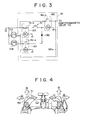
- Fig.4 As shown in Fig.4, by operating a switch 51 provided at upper grip part of a left control lever 50, revolving of an upper rotating body, and boom swing are switched. That is, by means of revolving operation, the operation in 1 ⁇ direction becomes right revolving and the operation in 2 ⁇ direction becomes left revolving. When the switch 51 is pushed, the operation in 1 ⁇ direction makes boom right swing and the operation in 2 ⁇ direction makes boom left swing.
- operations of lever for arm releasing and excavating, boom rising and falling, or bucket excavating and releasing are exemplified in Fig.4.
- 1 ⁇ indicates right revolving
- 2 ⁇ indicates left revolving
- 3 ⁇ indicates arm releasing
- 4 ⁇ indicates arm excavating.
- 5 ⁇ indicates boom falling
- 6 ⁇ indicates boom rising
- 7 ⁇ indicates bucket excavating
- 8 ⁇ indicates bucket releasing.
- the switch 51 is a toggle switch, a tumbler switchor the like, the switch is fixed to either the boom swing or the revolving whenever the switch 51 is operated. Also, in a case that the switch 51 is an automatic restoring type of push button switch, it is switched to the boom swing only when pushed with fingers.
- the present invention is not limited to the switching mode of the control lever as described above.
- the boom swing cylinder 15 is connected to the boom control valve 7. If the control valve is switched from the neutral position to the position c, the hydraulic oil is supplied to a head side of the boom swing cylinder 15. At that time, as shown in Figs.2a and 2b, the boom 30 can be swung, for example, right (e direction in the drawing) around the vertical axis VA. If the control valve is switched to the position d, the hydraulic oil is supplied to rod side of the boom swing cylinder 15. At that time, the boom 30 can be swung left (f direction in the drawing) around the vertical axis VA.
- the revolving motor 16 is connected to the revolving control valve 10. If switched from the neutral position to the position e, the revolving motor 16 is rotated in g direction to rotate the upper rotating body 31(see Fig.2b), for example, right. Also, if switched to the position f, the upper rotating body can be rotated left.
- the pilot line of the boom control valve 7 and the pilot line of the revolving control valve 10 are connected to the outlet port of the switching valve 17, respectively.
- This switching valve 17 is normally positioned at the positioni, and is connected to the control port of the revolving control valve 10. If switching signals is received from the switching control circuit 18 as a switchingcontroller, the switching valve 17 is switched to the position j by means of hydraulic signal sent via the electromagnetic valve 17a. Accordingly, the pilot pressure is supplied to the control port of the boom swing cylinder 15.
- the inlet port of the switching valve 17 is connected to the remote control valve 19 of the left control lever 50 (see Fig.4). If the left control lever 50 is shifted in 1 ⁇ direction, the pilot pressure is derived from the remote control valve 19a. Also, if the lever is shifted in 2 ⁇ direction, the pilot pressure is derived from the remote control valve 19b. These pilot pressures flow through the respective pilot lines 20a and 20b to the inlet port of the switching valve 17.
- pilot lines 20a and 20b are provided with pressure switches 21a and 21b as detector, respectively. If any one of the pilot lines 20a and 20b detects the pilot pressure, the signal is output to the switching control circuit 18.
- the detector is comprised of pressure switches provided in the pilot lines passing from the remote control valve to the switching valve.
- the control circuit of the present invention can be embodied without new sensor required.
- the revolving operation is carried out when the switch 51 is not pushed, the electromagnetic coil R 1 of the relay 183 is excited to open the contact point R 1-a .
- the relay 180 and 181 do not function and the switching valve 17 is never switched to the boom swing control valve 7. That is, when the switch 51 is not pushed, the operation mode is always fixed to the revolving operation. Only when the switch 51 is pushed, the operation mode is switched to the boom swing operation.
- a relay is provided between the control member and the switching valve, the relay being constructed to be self-held with signal output from the detector.
- the control circuit of the present invention can be embodied with a simple construction such that a relay circuit is added.
- the operation mode is not switched to the boom swing operation as long as the switch 51 is not pushed. Moreover, after the operation mode is switched to the boom swing operation, the boom swing operation is continued as long as the left control lever 50 is not restored to the neutral position. As a result, the revolving operation and the boom swing operation can be switched surely and safely. Also, even when fingers aretaken off the switch 51 during the boom swing operation, the operation mode is never switched to the revolving operation.
- the switching control means of the present invention is not limited to it and a microcomputer may be used to control in software.
- first actuator and the second actuator in the present invention are comprised of a revolving motor for revolving the upper rotating body and a boom swing cylinder for swinging the boom left and right around the vertical axis, respectively, in the above embodiment.
- first actuator may be the revolving motor and the second actuator may be an offset cylinder for offsetting the boom inmachine-width direction.
- the revolving operation and the boom swing operation are carried out by means of only one control lever, the revolving operation of the upper rotating body can be carried out during the control member is not operated. Also, only when operation of the control member is carried out, the boom swing operation can be carried out. Even when operation of the control member is released during the boom swing operation, the boom swing operation can be continued as long as the control lever is not restored to the neutral position. As a result, a trouble that the upper rotating body is revolved rapidly by means ofwrong operation can be prevented.
- the present invention is a control circuit for a construction machine for using a control lever for revolving and boom swing in common and switching pilot pressure via a switching valve, comprising: a switch for supplying a switching signal to the switching valve; a pressure switch for detecting whether the pilot pressure is output from a remote control valve or not; a switching control circuit for switching aposition of switch to a position for a boom swing cylinder when the switching signal is output from the switch and holding the position of switch at the position for the boom swing cylinder when the pilot pressure is detected by the pressure switch, to thereby prevent wrong operation in switching.
Landscapes
- Engineering & Computer Science (AREA)
- Mining & Mineral Resources (AREA)
- Civil Engineering (AREA)
- General Engineering & Computer Science (AREA)
- Structural Engineering (AREA)
- Physics & Mathematics (AREA)
- General Physics & Mathematics (AREA)
- Automation & Control Theory (AREA)
- Operation Control Of Excavators (AREA)
- Electrical Discharge Machining, Electrochemical Machining, And Combined Machining (AREA)
- Automatic Control Of Machine Tools (AREA)
- Constituent Portions Of Griding Lathes, Driving, Sensing And Control (AREA)
Abstract
Description
- The present invention relates to a control circuit for a construction machine for switching a plurality of actuators.
- Conventionally, a hydraulicexcavator equipped with a boom swing apparatus is known, for excavating a small place at the corner by swinging a boom left and right around a vertical axis. As an operating means for operating a boom swing cylinder, there is an operating means in which a foot pedal is used. Such an equipment with the foot pedal limits space in foot side. Also, equipment with a nibbler or a breaker as an option increases the number of pedals and makes operationsthereof complex.
- For this reason, an operation lever can be used, which performs together operation of the boom swing cylinder and operation of an actuator, for example a revolving motor that is not operated in combination of boom swing.
- In this case, when after switching from revolving to boom swing, if the switching operation is not recognized, there is a problem that mis-operation can occur that the revolving is derived from the operation carried out for a boom swing purpose.
- An object of the present invention is to provide a control circuit for a construction machine capable of certainly preventingwrong operation in a case that a plurality of actuators are operated by means of only onecontrol lever.
- The control circuit for a construction machine according to the present invention has followingconstitution.
- The present invention comprises: a control lever for carrying out operations of a first actuator and a second actuator in common; a switching valve or a selector valve for supplying pilot pressure output from a remote control valve by means of operation of the control lever to a control port in any one of the first and the second actuators; a control member for supplying a switching signal to the switching valve; adetector for detecting whether the pilot pressure is output from the remote control valve or not; and a switching controller for switching a change-over position in the switching valve from the first actuator to the second actuator when the switching signal is output from the control member and holding the position at the second actuator when output of the pilot pressure is detected by the detector.
- According to the present invention, if the control member is operated, the switching valve switches a pilot pressure supply place to which the pilot pressure is output from the remote control valve of the control lever, from the first actuator to the second actuator, and then the detector detects the pilot pressure if the pilot pressure appears in a pilot line by means of operation of thecontrol lever. The switching control means holds the switching valve at the second actuator when the switching signal is output from the control member and when output of the pilot pressure is detected by the detector. Thereby, switching from the first actuator to the second actuator does not occur as long as the control member is not operated. Also, when the control lever is operated in a state that the control member is operated to switch the position of switch to the second actuator, the position cannot be switched to the first actuator even if the control member is off, as long as the control lever is not restored in neutral position. Therefore, wrong operation can be prevented in switching. Also, even if a finger is taken off the control member during operation, a bad situation that the position of switch is switched to other actuator can be prevented.
-
- Fig.1 is a diagram showing a control circuit for a construction machine according to one embodiment of the present invention;
- Fig.2a is a plan view of the construction machine for explaining boom swing operation and Fig.2b is a side view thereof;
- Fig.3 is a circuit diagram showing constitution of a switching control circuit shown in Fig.1; and
- Fig.4 is a schematic view showing operations ofa control lever.
-
- Now, the present invention will be explained on the basis of embodiments shown in the drawings. These embodiments are only preferred embodiments of the present invention and the present invention is not limited to them.
- Fig.1 shows one embodiment of a control circuit for a construction machine according to the present invention.
- In Fig.1, a variable capacity type of
hydraulic pump 2 and apilot pump 3 are operated, respectively, by means of driving of an engine 1 equipped in an upperrotating body of the construction machine. - Hydraulic oil discharged from the
hydraulic pump 2 is supplied to a right traveling control valve 4, aboom control valve 5, abucket control valve 6, a boomswing control valve 7 and acontrol valve 8 for a crusher/breaker as an option apparatus, arranged in a center bypass line LC on the left of Fig.1. The hydraulic oil is also supplied to a lefttraveling control valve 9, a revolvingcontrol valve 10 and anarm control valve 11, arranged in a center bypass line RC on the right of Fig.1. The hydraulic oil discharged from thepilot pump 3 is used as a pressure source for various controllers. - A
straight traveling valve 12 provided upstream in thetraveling control valve 4, 9 has positions of switch comprised of a, b and is normally held at the position a. - At the position a, the hydraulic oil from the
hydraulic pump 2 is independently supplied to the left center bypass line LC and the right center bypass line RC. If, in a state that the right and left traveling levers are operated to the same position, for example the boom or the arm is operated, then thestraight traveling valve 12 is switched from the position a to the position b. Accordingly, the hydraulic oil from thehydraulic pump 2 flows in parallel to the left center bypass line LC and the right center bypass line RC. At that time, even if a combined operation is carried out such that the boom is risen and fallenwhile a travelingmotor 16 is driven, the hydraulic oil from thehydraulic pump 2 is supplied equally to the left and the right traveling motors. By means of this, the straight traveling can be kept. Also, in the drawing, 13 is a conflux valve for increasing the boom-up speed and 14 is a cut valve for making the hydraulic oil flow in the left center bypass line LC. - Next, switching operation of the control lever will be explained with reference to Fig.4. As shown in Fig.4, by operating a
switch 51 provided at upper grip part of aleft control lever 50, revolving of an upper rotating body, and boom swing are switched. That is, by means of revolving operation, the operation in 1 ○ direction becomes right revolving and the operation in 2 ○direction becomes left revolving. When theswitch 51 is pushed, the operation in 1 ○direction makes boom right swing and the operation in 2 ○ direction makes boom left swing. For reference, operations of lever for arm releasing and excavating, boom rising and falling, or bucket excavating and releasing are exemplified in Fig.4. That is, in the leftcontrol lever, 1 ○ indicates right revolving, 2 ○ indicates left revolving, 3 ○ indicates arm releasing and 4 ○ indicates arm excavating. Also, in the right control lever, 5 ○ indicates boom falling, 6 ○ indicates boom rising, 7 ○ indicates bucket excavating and 8 ○ indicates bucket releasing. - Also, in a case that the
switch 51 is a toggle switch, a tumbler switchor the like, the switch is fixed to either the boom swing or the revolving whenever theswitch 51 is operated. Also, in a case that theswitch 51 is an automatic restoring type of push button switch, it is switched to the boom swing only when pushed with fingers. Here, the present invention is not limited to the switching mode of the control lever as described above. - Now, a switching operational circuit of the revolving motor (as first actuator) and the boom swing cylinder (as second actuator) related to the present invention will be explained. Explanation for operation of actuators except for them will be omitted for simplification.
- The
boom swing cylinder 15 is connected to theboom control valve 7. If the control valve is switched from the neutral position to the position c, the hydraulic oil is supplied to a head side of theboom swing cylinder 15. At that time, as shown in Figs.2a and 2b, theboom 30 can be swung, for example, right (e direction in the drawing) around the vertical axis VA. If the control valve is switched to the position d, the hydraulic oil is supplied to rod side of theboom swing cylinder 15. At that time, theboom 30 can be swung left (f direction in the drawing) around the vertical axis VA. - The revolving
motor 16 is connected to the revolvingcontrol valve 10. If switched from the neutral position to the position e, the revolvingmotor 16 is rotated in g direction to rotate the upper rotating body 31(see Fig.2b), for example, right. Also, if switched to the position f, the upper rotating body can be rotated left. - The pilot line of the
boom control valve 7 and the pilot line of the revolvingcontrol valve 10 are connected to the outlet port of theswitching valve 17, respectively. - This
switching valve 17 is normally positioned at the positioni, and is connected to the control port of the revolvingcontrol valve 10. If switching signals is received from theswitching control circuit 18 as a switchingcontroller, theswitching valve 17 is switched to the position j by means of hydraulic signal sent via theelectromagnetic valve 17a. Accordingly, the pilot pressure is supplied to the control port of theboom swing cylinder 15. - The inlet port of the
switching valve 17 is connected to theremote control valve 19 of the left control lever 50 (see Fig.4). If theleft control lever 50 is shifted in 1 ○ direction, the pilot pressure is derived from theremote control valve 19a. Also, if the lever is shifted in 2 ○ direction, the pilot pressure is derived from theremote control valve 19b. These pilot pressures flow through therespective pilot lines 20a and 20b to the inlet port of the switchingvalve 17. - These
pilot lines 20a and 20b are provided withpressure switches 21a and 21b as detector, respectively. If any one of thepilot lines 20a and 20b detects the pilot pressure, the signal is output to the switchingcontrol circuit 18. - Therefore, in the present invention, the detector is comprised of pressure switches provided in the pilot lines passing from the remote control valve to the switching valve. In this case, because the detector is constructed with the conventional pressure switch for detecting operational pressure from the remote control valve, the control circuit of the present invention can be embodied without new sensor required.
- Next, construction of the switching
control circuit 18 will be explained with reference to Fig.3. - First, if the push-button switch (control member) 51 provided in grip of the
left control lever 50 is pushed, an electromagnetic coil R3 of therelay 180 is excited. As a result, the contact point R3-a is closed. Thereby, the solenoid of theelectromagnetic valve 17a, is turned on and theelectromagnetic valve 17a is switched from the intercepting position k to turn-on position or conducting position 1. - If the hydraulic signal is applied to the control port of the switching
valve 17 via theelectromagnetic valve 17a, the switchingvalve 17 is switched to the position j. As a result, thepilot lines 20a and 20b are connected to the control port of the boomswing control valve 7. Accordingly, 1 ○ and 2 ○ operations by theleft control lever 50 function as the boom swing operations. - If the contact point R3-a is closed, current flows through the signal line 180a to the
relay 181. As a result, the electromagnetic coil R2 is excited and the contact point R2-a is closed. In this state, if theleft control lever 50 is shifted in any of 1 ○ direction and 2 ○ direction, thepressure switch 21a or 21b is closed to turn on electricity and to make current flow. This current flows via the contact point R2-a anddiode 182 to the electromagnetic coil R3. As a result, therelay 180 is self-held. That is, even when fingers are taken off theswitch 51, the switchingvalve 17 is held at the position j. Accordingly, the boom swing operation is continued. - Also, if the revolving operation is carried out when the
switch 51 is not pushed, the electromagnetic coil R1 of therelay 183 is excited to open the contact point R1-a. As a result, even when theswitch 51 is pushed, therelay valve 17 is never switched to the boomswing control valve 7. That is, when theswitch 51 is not pushed, the operation mode is always fixed to the revolving operation. Only when theswitch 51 is pushed, the operation mode is switched to the boom swing operation. - In the present invention, a relay is provided between the control member and the switching valve, the relay being constructed to be self-held with signal output from the detector. In this case, the control circuit of the present invention can be embodied with a simple construction such that a relay circuit is added.
- As described above, in the control circuit of the present embodiment, the operation mode is not switched to the boom swing operation as long as the
switch 51 is not pushed. Moreover, after the operation mode is switched to the boom swing operation, the boom swing operation is continued as long as theleft control lever 50 is not restored to the neutral position. As a result, the revolving operation and the boom swing operation can be switched surely and safely. Also, even when fingers aretaken off theswitch 51 during the boom swing operation, the operation mode is never switched to the revolving operation. - Moreover, although the relay is used to control in sequence in the above embodiment, the switching control means of the present invention is not limited to it and a microcomputer may be used to control in software.
- Also, the first actuator and the second actuator in the present invention are comprised of a revolving motor for revolving the upper rotating body and a boom swing cylinder for swinging the boom left and right around the vertical axis, respectively, in the above embodiment. In addition, the first actuator may be the revolving motor and the second actuator may be an offset cylinder for offsetting the boom inmachine-width direction.
- In this case, when the revolving operation and the boom swing operation are carried out by means of only one control lever, the revolving operation of the upper rotating body can be carried out during the control member is not operated. Also, only when operation of the control member is carried out, the boom swing operation can be carried out. Even when operation of the control member is released during the boom swing operation, the boom swing operation can be continued as long as the control lever is not restored to the neutral position. As a result, a trouble that the upper rotating body is revolved rapidly by means ofwrong operation can be prevented.
- In brief, if it is combination of actuators without combined operation, for example, any lever operation in standard operating mode prescribed with ISO and lever operation of option apparatus can be combined.
- As described above, although one embodiment of the present invention is disclosed, the scope of the protection of the present invention is not limited to it.
- The present invention is a control circuit for a construction machine for using a control lever for revolving and boom swing in common and switching pilot pressure via a switching valve, comprising: a switch for supplying a switching signal to the switching valve; a pressure switch for detecting whether the pilot pressure is output from a remote control valve or not; a switching control circuit for switching aposition of switch to a position for a boom swing cylinder when the switching signal is output from the switch and holding the position of switch at the position for the boom swing cylinder when the pilot pressure is detected by the pressure switch, to thereby prevent wrong operation in switching.
Claims (4)
- A control circuit for a construction machine, comprising:a control lever for carrying out operations of a first actuator and a second actuator in common;a switching valve for supplying pilot pressure output from a remote control valve by means of operation of saidcontrol lever to a control port in any one of the first and the second actuators;a control member for supplying a switching signal to said switching valve;a detector for detecting whether the pilot pressure is output from said remote control valve or not; anda switching controller for switching a change-over position in said switching valve from the first actuator to the second actuator when the switching signal is output from said control member and holding saidposition at the second actuator when output of the pilot pressure is detected by said detector.
- The control circuit according to claim 1, further comprising a relay provided between said control member and said switching valve, the relay being self-held with signal output from saiddetector.
- The control circuit according to claim 1, wherein said first actuator is a revolving motor for rotating an upper rotating body and said second actuator is a boom swing cylinder for swinging a boom left and right around a vertical axis or an offset cylinder for offsetting the boom in a machine-width direction.
- The control circuit according to claim 1, wherein said detector includes a pressure switch provided in a pilot line passing from said remote control valve to said switching valve.
Applications Claiming Priority (2)
| Application Number | Priority Date | Filing Date | Title |
|---|---|---|---|
| JP2001048962A JP3661596B2 (en) | 2001-02-23 | 2001-02-23 | Construction machine operation circuit |
| JP2001048962 | 2001-02-23 |
Publications (2)
| Publication Number | Publication Date |
|---|---|
| EP1236834A1 true EP1236834A1 (en) | 2002-09-04 |
| EP1236834B1 EP1236834B1 (en) | 2003-09-10 |
Family
ID=18910138
Family Applications (1)
| Application Number | Title | Priority Date | Filing Date |
|---|---|---|---|
| EP20020001876 Expired - Lifetime EP1236834B1 (en) | 2001-02-23 | 2002-01-28 | Control circuit for a construction machine |
Country Status (6)
| Country | Link |
|---|---|
| US (1) | US6598394B2 (en) |
| EP (1) | EP1236834B1 (en) |
| JP (1) | JP3661596B2 (en) |
| KR (1) | KR100479141B1 (en) |
| AT (1) | ATE249554T1 (en) |
| DE (1) | DE60200027T2 (en) |
Cited By (2)
| Publication number | Priority date | Publication date | Assignee | Title |
|---|---|---|---|---|
| EP2362026A1 (en) * | 2010-02-25 | 2011-08-31 | Yanmar Co., Ltd. | Work machine |
| EP3124798A4 (en) * | 2014-03-24 | 2018-01-24 | Hitachi Construction Machinery Co., Ltd. | Hydraulic system for work vehicle |
Families Citing this family (7)
| Publication number | Priority date | Publication date | Assignee | Title |
|---|---|---|---|---|
| JP2012017589A (en) * | 2010-07-07 | 2012-01-26 | Sanyo Kiki Co Ltd | Control device of front loader |
| KR101877059B1 (en) * | 2012-01-30 | 2018-07-10 | 두산인프라코어 주식회사 | Control apparatus in a construction machine |
| KR101846030B1 (en) * | 2012-01-30 | 2018-04-05 | 두산인프라코어 주식회사 | control device for construction machine |
| JP6088508B2 (en) | 2012-06-08 | 2017-03-01 | 住友重機械工業株式会社 | Excavator control method and control apparatus |
| EP3936969A1 (en) * | 2020-07-08 | 2022-01-12 | Manitou Equipment America, LLC | Offset control stick system and method |
| JP7643045B2 (en) * | 2021-01-12 | 2025-03-11 | コベルコ建機株式会社 | Work machine and remote operation support system |
| JP7504815B2 (en) | 2021-01-27 | 2024-06-24 | 株式会社クボタ | Rotating work machine |
Citations (4)
| Publication number | Priority date | Publication date | Assignee | Title |
|---|---|---|---|---|
| US5125232A (en) * | 1990-05-29 | 1992-06-30 | Kubota Corporation | Control change system for a hydraulic working vehicle |
| EP0712062A2 (en) * | 1994-11-08 | 1996-05-15 | Jungheinrich Aktiengesellschaft | Manually-actuated control device for an operator stand or seat |
| EP0783057A1 (en) * | 1996-01-08 | 1997-07-09 | Hitachi Construction Machinery Co., Ltd. | Hydraulic drive system for construction machines |
| EP0849406A1 (en) * | 1996-12-20 | 1998-06-24 | Hitachi Construction Machinery Co., Ltd. | Hydraulic drive system for hydraulic excavator |
Family Cites Families (5)
| Publication number | Priority date | Publication date | Assignee | Title |
|---|---|---|---|---|
| JPS56121752A (en) | 1980-02-29 | 1981-09-24 | Toyoda Gosei Co Ltd | Mold for compression forming |
| JPS6244956A (en) | 1985-08-21 | 1987-02-26 | Fuji Electric Corp Res & Dev Ltd | Impregnation of electrolyte in fused carbonate fuel cell |
| JPH0289051A (en) | 1988-09-27 | 1990-03-29 | Fuji Photo Film Co Ltd | Direct positive color photographic sensitive material |
| JP3164901B2 (en) | 1992-08-18 | 2001-05-14 | ヤンマーディーゼル株式会社 | Operating mechanism of all-turn excavator |
| JP3177097B2 (en) * | 1994-06-28 | 2001-06-18 | 日立建機株式会社 | Safety equipment for construction machinery |
-
2001
- 2001-02-23 JP JP2001048962A patent/JP3661596B2/en not_active Expired - Lifetime
-
2002
- 2002-01-28 EP EP20020001876 patent/EP1236834B1/en not_active Expired - Lifetime
- 2002-01-28 AT AT02001876T patent/ATE249554T1/en not_active IP Right Cessation
- 2002-01-28 US US10/055,927 patent/US6598394B2/en not_active Expired - Fee Related
- 2002-01-28 DE DE60200027T patent/DE60200027T2/en not_active Expired - Lifetime
- 2002-02-22 KR KR10-2002-0009415A patent/KR100479141B1/en not_active Expired - Fee Related
Patent Citations (4)
| Publication number | Priority date | Publication date | Assignee | Title |
|---|---|---|---|---|
| US5125232A (en) * | 1990-05-29 | 1992-06-30 | Kubota Corporation | Control change system for a hydraulic working vehicle |
| EP0712062A2 (en) * | 1994-11-08 | 1996-05-15 | Jungheinrich Aktiengesellschaft | Manually-actuated control device for an operator stand or seat |
| EP0783057A1 (en) * | 1996-01-08 | 1997-07-09 | Hitachi Construction Machinery Co., Ltd. | Hydraulic drive system for construction machines |
| EP0849406A1 (en) * | 1996-12-20 | 1998-06-24 | Hitachi Construction Machinery Co., Ltd. | Hydraulic drive system for hydraulic excavator |
Cited By (3)
| Publication number | Priority date | Publication date | Assignee | Title |
|---|---|---|---|---|
| EP2362026A1 (en) * | 2010-02-25 | 2011-08-31 | Yanmar Co., Ltd. | Work machine |
| US8272468B2 (en) | 2010-02-25 | 2012-09-25 | Yanmar Co., Ltd. | Work machine |
| EP3124798A4 (en) * | 2014-03-24 | 2018-01-24 | Hitachi Construction Machinery Co., Ltd. | Hydraulic system for work vehicle |
Also Published As
| Publication number | Publication date |
|---|---|
| US6598394B2 (en) | 2003-07-29 |
| DE60200027D1 (en) | 2003-10-16 |
| KR100479141B1 (en) | 2005-03-30 |
| ATE249554T1 (en) | 2003-09-15 |
| JP2002250053A (en) | 2002-09-06 |
| DE60200027T2 (en) | 2004-05-13 |
| US20020116921A1 (en) | 2002-08-29 |
| JP3661596B2 (en) | 2005-06-15 |
| KR20020069142A (en) | 2002-08-29 |
| EP1236834B1 (en) | 2003-09-10 |
Similar Documents
| Publication | Publication Date | Title |
|---|---|---|
| EP1790859B1 (en) | Hydraulic controller for working machine | |
| KR0135625B1 (en) | Hydraulic drive system of construction machinery | |
| KR101155718B1 (en) | An apparatus for controlling the starting speed of an excavator | |
| EP3216927B1 (en) | Driving straight ahead device for construction machine and control method therefor | |
| US6598394B2 (en) | Control circuit for construction machine | |
| JPH0719207A (en) | Drive controller for hydraulic machine | |
| JP3262236B2 (en) | Control equipment for construction machinery | |
| JP3741729B2 (en) | Electrohydraulic control mechanism for power shift transmission | |
| JP7170084B2 (en) | Work machine control system | |
| CN114198359B (en) | A safe operation system and engineering machinery | |
| CN110226010B (en) | Hydraulic control system for construction machine | |
| KR100249722B1 (en) | Control apparatus of hydraulic excavation working machine | |
| KR100448537B1 (en) | Method and apparatus for locking machine | |
| KR101156859B1 (en) | Apparatus for preventing unexpected operation of an excavator | |
| EP4116505B1 (en) | Method for controlling a third function operation in a hydraulic control system for a work vehicle | |
| KR102475528B1 (en) | Control system and control method for construction machine | |
| EP4600429A1 (en) | Automatic operation construction machine | |
| JPH10311065A (en) | Control device of hydraulic construction machinery | |
| CN111512051B (en) | Hydraulic drive device for working machine | |
| JPH06264905A (en) | Hydraulic driving device for construction machine | |
| JP3177097B2 (en) | Safety equipment for construction machinery | |
| JPH108501A (en) | Operation control method for manned vehicle | |
| JPH0730771Y2 (en) | Operating equipment for construction machinery | |
| JPH0771411A (en) | Working pressure selector device and selecting method for work machine | |
| JPH0649867A (en) | Safety device of working machine |
Legal Events
| Date | Code | Title | Description |
|---|---|---|---|
| PUAI | Public reference made under article 153(3) epc to a published international application that has entered the european phase |
Free format text: ORIGINAL CODE: 0009012 |
|
| 17P | Request for examination filed |
Effective date: 20020128 |
|
| AK | Designated contracting states |
Kind code of ref document: A1 Designated state(s): AT BE CH CY DE DK ES FI FR GB GR IE IT LI LU MC NL PT SE TR |
|
| AX | Request for extension of the european patent |
Free format text: AL;LT;LV;MK;RO;SI |
|
| GRAH | Despatch of communication of intention to grant a patent |
Free format text: ORIGINAL CODE: EPIDOS IGRA |
|
| AKX | Designation fees paid |
Designated state(s): AT BE CH CY DE DK ES FI FR GB GR IE IT LI LU MC NL PT SE TR |
|
| R17P | Request for examination filed (corrected) |
Effective date: 20020128 |
|
| GRAH | Despatch of communication of intention to grant a patent |
Free format text: ORIGINAL CODE: EPIDOS IGRA |
|
| GRAA | (expected) grant |
Free format text: ORIGINAL CODE: 0009210 |
|
| AK | Designated contracting states |
Kind code of ref document: B1 Designated state(s): AT BE CH CY DE DK ES FI FR GB GR IE IT LI LU MC NL PT SE TR |
|
| PG25 | Lapsed in a contracting state [announced via postgrant information from national office to epo] |
Ref country code: FI Free format text: LAPSE BECAUSE OF FAILURE TO SUBMIT A TRANSLATION OF THE DESCRIPTION OR TO PAY THE FEE WITHIN THE PRESCRIBED TIME-LIMIT Effective date: 20030910 Ref country code: NL Free format text: LAPSE BECAUSE OF FAILURE TO SUBMIT A TRANSLATION OF THE DESCRIPTION OR TO PAY THE FEE WITHIN THE PRESCRIBED TIME-LIMIT Effective date: 20030910 Ref country code: BE Free format text: LAPSE BECAUSE OF FAILURE TO SUBMIT A TRANSLATION OF THE DESCRIPTION OR TO PAY THE FEE WITHIN THE PRESCRIBED TIME-LIMIT Effective date: 20030910 Ref country code: LI Free format text: LAPSE BECAUSE OF FAILURE TO SUBMIT A TRANSLATION OF THE DESCRIPTION OR TO PAY THE FEE WITHIN THE PRESCRIBED TIME-LIMIT Effective date: 20030910 Ref country code: AT Free format text: LAPSE BECAUSE OF FAILURE TO SUBMIT A TRANSLATION OF THE DESCRIPTION OR TO PAY THE FEE WITHIN THE PRESCRIBED TIME-LIMIT Effective date: 20030910 Ref country code: TR Free format text: LAPSE BECAUSE OF FAILURE TO SUBMIT A TRANSLATION OF THE DESCRIPTION OR TO PAY THE FEE WITHIN THE PRESCRIBED TIME-LIMIT Effective date: 20030910 Ref country code: CH Free format text: LAPSE BECAUSE OF FAILURE TO SUBMIT A TRANSLATION OF THE DESCRIPTION OR TO PAY THE FEE WITHIN THE PRESCRIBED TIME-LIMIT Effective date: 20030910 Ref country code: CY Free format text: LAPSE BECAUSE OF FAILURE TO SUBMIT A TRANSLATION OF THE DESCRIPTION OR TO PAY THE FEE WITHIN THE PRESCRIBED TIME-LIMIT Effective date: 20030910 |
|
| REG | Reference to a national code |
Ref country code: GB Ref legal event code: FG4D |
|
| REG | Reference to a national code |
Ref country code: CH Ref legal event code: EP |
|
| REF | Corresponds to: |
Ref document number: 60200027 Country of ref document: DE Date of ref document: 20031016 Kind code of ref document: P |
|
| REG | Reference to a national code |
Ref country code: IE Ref legal event code: FG4D |
|
| PG25 | Lapsed in a contracting state [announced via postgrant information from national office to epo] |
Ref country code: SE Free format text: LAPSE BECAUSE OF FAILURE TO SUBMIT A TRANSLATION OF THE DESCRIPTION OR TO PAY THE FEE WITHIN THE PRESCRIBED TIME-LIMIT Effective date: 20031210 Ref country code: GR Free format text: LAPSE BECAUSE OF FAILURE TO SUBMIT A TRANSLATION OF THE DESCRIPTION OR TO PAY THE FEE WITHIN THE PRESCRIBED TIME-LIMIT Effective date: 20031210 Ref country code: DK Free format text: LAPSE BECAUSE OF FAILURE TO SUBMIT A TRANSLATION OF THE DESCRIPTION OR TO PAY THE FEE WITHIN THE PRESCRIBED TIME-LIMIT Effective date: 20031210 |
|
| PG25 | Lapsed in a contracting state [announced via postgrant information from national office to epo] |
Ref country code: ES Free format text: LAPSE BECAUSE OF FAILURE TO SUBMIT A TRANSLATION OF THE DESCRIPTION OR TO PAY THE FEE WITHIN THE PRESCRIBED TIME-LIMIT Effective date: 20031221 |
|
| PG25 | Lapsed in a contracting state [announced via postgrant information from national office to epo] |
Ref country code: PT Free format text: LAPSE BECAUSE OF FAILURE TO SUBMIT A TRANSLATION OF THE DESCRIPTION OR TO PAY THE FEE WITHIN THE PRESCRIBED TIME-LIMIT Effective date: 20031222 |
|
| PG25 | Lapsed in a contracting state [announced via postgrant information from national office to epo] |
Ref country code: IE Free format text: LAPSE BECAUSE OF NON-PAYMENT OF DUE FEES Effective date: 20040128 Ref country code: LU Free format text: LAPSE BECAUSE OF NON-PAYMENT OF DUE FEES Effective date: 20040128 |
|
| PG25 | Lapsed in a contracting state [announced via postgrant information from national office to epo] |
Ref country code: MC Free format text: LAPSE BECAUSE OF NON-PAYMENT OF DUE FEES Effective date: 20040131 |
|
| NLV1 | Nl: lapsed or annulled due to failure to fulfill the requirements of art. 29p and 29m of the patents act | ||
| REG | Reference to a national code |
Ref country code: CH Ref legal event code: PL |
|
| ET | Fr: translation filed | ||
| PLBE | No opposition filed within time limit |
Free format text: ORIGINAL CODE: 0009261 |
|
| STAA | Information on the status of an ep patent application or granted ep patent |
Free format text: STATUS: NO OPPOSITION FILED WITHIN TIME LIMIT |
|
| 26N | No opposition filed |
Effective date: 20040614 |
|
| REG | Reference to a national code |
Ref country code: IE Ref legal event code: MM4A |
|
| PGFP | Annual fee paid to national office [announced via postgrant information from national office to epo] |
Ref country code: FR Payment date: 20120202 Year of fee payment: 11 |
|
| PGFP | Annual fee paid to national office [announced via postgrant information from national office to epo] |
Ref country code: DE Payment date: 20120125 Year of fee payment: 11 |
|
| PGFP | Annual fee paid to national office [announced via postgrant information from national office to epo] |
Ref country code: GB Payment date: 20120125 Year of fee payment: 11 Ref country code: IT Payment date: 20120117 Year of fee payment: 11 |
|
| GBPC | Gb: european patent ceased through non-payment of renewal fee |
Effective date: 20130128 |
|
| REG | Reference to a national code |
Ref country code: FR Ref legal event code: ST Effective date: 20130930 |
|
| PG25 | Lapsed in a contracting state [announced via postgrant information from national office to epo] |
Ref country code: DE Free format text: LAPSE BECAUSE OF NON-PAYMENT OF DUE FEES Effective date: 20130801 |
|
| REG | Reference to a national code |
Ref country code: DE Ref legal event code: R119 Ref document number: 60200027 Country of ref document: DE Effective date: 20130801 |
|
| PG25 | Lapsed in a contracting state [announced via postgrant information from national office to epo] |
Ref country code: FR Free format text: LAPSE BECAUSE OF NON-PAYMENT OF DUE FEES Effective date: 20130131 Ref country code: GB Free format text: LAPSE BECAUSE OF NON-PAYMENT OF DUE FEES Effective date: 20130128 |
|
| PG25 | Lapsed in a contracting state [announced via postgrant information from national office to epo] |
Ref country code: IT Free format text: LAPSE BECAUSE OF NON-PAYMENT OF DUE FEES Effective date: 20130128 |