EP1235963B1 - Explosion-resistant wall construction - Google Patents
Explosion-resistant wall construction Download PDFInfo
- Publication number
- EP1235963B1 EP1235963B1 EP00991314A EP00991314A EP1235963B1 EP 1235963 B1 EP1235963 B1 EP 1235963B1 EP 00991314 A EP00991314 A EP 00991314A EP 00991314 A EP00991314 A EP 00991314A EP 1235963 B1 EP1235963 B1 EP 1235963B1
- Authority
- EP
- European Patent Office
- Prior art keywords
- wall panel
- stop element
- wall
- wall construction
- supporting face
- Prior art date
- Legal status (The legal status is an assumption and is not a legal conclusion. Google has not performed a legal analysis and makes no representation as to the accuracy of the status listed.)
- Expired - Lifetime
Links
- 238000010276 construction Methods 0.000 title claims abstract description 25
- 238000004880 explosion Methods 0.000 title claims abstract description 16
- 230000003993 interaction Effects 0.000 claims abstract description 3
- 239000000945 filler Substances 0.000 claims description 2
- 239000012528 membrane Substances 0.000 description 4
- 230000003014 reinforcing effect Effects 0.000 description 2
- 239000011324 bead Substances 0.000 description 1
Images

Classifications
-
- E—FIXED CONSTRUCTIONS
- E04—BUILDING
- E04B—GENERAL BUILDING CONSTRUCTIONS; WALLS, e.g. PARTITIONS; ROOFS; FLOORS; CEILINGS; INSULATION OR OTHER PROTECTION OF BUILDINGS
- E04B1/00—Constructions in general; Structures which are not restricted either to walls, e.g. partitions, or floors or ceilings or roofs
- E04B1/62—Insulation or other protection; Elements or use of specified material therefor
- E04B1/92—Protection against other undesired influences or dangers
- E04B1/98—Protection against other undesired influences or dangers against vibrations or shocks; against mechanical destruction, e.g. by air-raids
-
- B—PERFORMING OPERATIONS; TRANSPORTING
- B65—CONVEYING; PACKING; STORING; HANDLING THIN OR FILAMENTARY MATERIAL
- B65D—CONTAINERS FOR STORAGE OR TRANSPORT OF ARTICLES OR MATERIALS, e.g. BAGS, BARRELS, BOTTLES, BOXES, CANS, CARTONS, CRATES, DRUMS, JARS, TANKS, HOPPERS, FORWARDING CONTAINERS; ACCESSORIES, CLOSURES, OR FITTINGS THEREFOR; PACKAGING ELEMENTS; PACKAGES
- B65D90/00—Component parts, details or accessories for large containers
- B65D90/22—Safety features
- B65D90/32—Arrangements for preventing, or minimising the effect of, excessive or insufficient pressure
-
- B—PERFORMING OPERATIONS; TRANSPORTING
- B65—CONVEYING; PACKING; STORING; HANDLING THIN OR FILAMENTARY MATERIAL
- B65D—CONTAINERS FOR STORAGE OR TRANSPORT OF ARTICLES OR MATERIALS, e.g. BAGS, BARRELS, BOTTLES, BOXES, CANS, CARTONS, CRATES, DRUMS, JARS, TANKS, HOPPERS, FORWARDING CONTAINERS; ACCESSORIES, CLOSURES, OR FITTINGS THEREFOR; PACKAGING ELEMENTS; PACKAGES
- B65D90/00—Component parts, details or accessories for large containers
- B65D90/22—Safety features
- B65D90/32—Arrangements for preventing, or minimising the effect of, excessive or insufficient pressure
- B65D90/325—Arrangements for preventing, or minimising the effect of, excessive or insufficient pressure due to explosion, e.g. inside the container
-
- F—MECHANICAL ENGINEERING; LIGHTING; HEATING; WEAPONS; BLASTING
- F16—ENGINEERING ELEMENTS AND UNITS; GENERAL MEASURES FOR PRODUCING AND MAINTAINING EFFECTIVE FUNCTIONING OF MACHINES OR INSTALLATIONS; THERMAL INSULATION IN GENERAL
- F16B—DEVICES FOR FASTENING OR SECURING CONSTRUCTIONAL ELEMENTS OR MACHINE PARTS TOGETHER, e.g. NAILS, BOLTS, CIRCLIPS, CLAMPS, CLIPS OR WEDGES; JOINTS OR JOINTING
- F16B2200/00—Constructional details of connections not covered for in other groups of this subclass
- F16B2200/67—Rigid angle couplings
Definitions
- the invention relates to a wall construction with increased resistance to overpressure, for example to explosions, which wall construction forms part of an explosion chamber and comprises an essentially flat wall panel, adjoining structural components and at least one stop element, the wall panel and the at least one stop element being welded to the adjoining structural components, said at least one stop element having a supporting face facing the wall panel, which supporting face can be brought into interaction with the wall panel on deformation of the wall panel under the influence of an overpressure on that side thereof that faces away from the stop element.
- Such a wall construction is disclosed in US-A 4 632 041, in which an explosion chamber is described.
- This known wall construction has a flat wall panel that is welded to a cylindrical wall with a number of triangular support pieces thereon. The purpose of these support pieces is to restrict deformations of the weld joint between the cylindrical wall and the wall panel, which deformations can be the consequence of an explosion in the explosion chamber.
- the wall construction further comprises stop elements formed by vertical and horizontal girders having supporting faces facing the wall panel. The girders are being welded to the cylindrical wall as well as to the wall panel resulting in a very rigid construction.
- the aim of the invention is to provide a wall construction that does not have these disadvantages. Said aim is achieved in that the at least one stop element is formed as a stop block which only covers an edge area of the wall panel and contacts said wall panel.
- the wall construction according to the invention can undergo substantial deformation without this resulting in failure by only using some simple and relatively small stop blocks.
- the wall panel can acquire a curvature such that it starts to act as a membrane.
- the resulting membrane stresses can be absorbed by the wall panel exceedingly well.
- the stop element is located at the place where the part of the wall panel adjoins a weld. This prevents the occurrence of excessive flexural deformation at the location of the weld, which could easily lead to failure of the weld.
- the supporting face of the stop element can be located some distance away from the wall panel in connection with tolerances. If necessary, this distance can subsequently be reduced by means of filler plates.
- the stop elements thus also have the advantage that they can be fitted to an existing wall construction at a later date.
- the stress pattern in the deformed wall panel can be favourably influenced in an embodiment in which starting from the contact between stop element and wall panel away from the structural component adjoining said stop element an increasing opening is present between the supporting face of the stop element and the wall panel.
- the supporting face of the stop element is preferably curved.
- the stop element can have a recess such that the supporting face terminates some distance away from the adjoining structural component.
- multiple stop elements can be provided regular distances apart.
- a continuous support is also possible.
- the stop elements also reduce the shear stresses in the panel and therefore also the risk of failure as a consequence of shear stresses.
- the explosion chamber 1 shown in Figure 1 has a wall construction 2 according to the invention that is welded all round to adjoining structural components, which are constructed as walls 3.
- the explosion chamber also has an access door, which is not shown, as well as other facilities that are required with such a chamber.
- the wall construction according to the invention has a wall panel 4, to the inside of which reinforcing bars, for example T-bars 5, are welded in the customary manner.
- Stop elements 6 are fitted on the outside of the wall panel. These stop elements 6 are welded to the adjoining structural components 3 and have a curved supporting face 7.
- the wall panel 4 As soon as an explosion occurs in the explosion chamber, high pressure is exerted on the wall panel 4 causing it to deform into the state shown in Figure 3.
- the reinforcing bars 5 also deform.
- the wall panel 4 is able to absorb substantial forces in this deformed state since it is exposed to membrane stresses in its surface. As it is known, a panel is well able to withstand such membrane stresses.
- the support bars 5 of course have a supporting function.
- the wall panel 4 has come into contact with the supporting face 7 of stop element 6 during deformation.
- the curvature of said supporting face 7 has been so chosen that the wall panel 4 has been gradually bent outwards from the weld 8.
- excessive flexural stresses, especially in the outermost fibres of the wall panel 4 are avoided.
- the weld 8 is hardly exposed to flexural stresses, as a result of which the risk of failure of the weld is largely prevented.
- the advantage of the wall construction of the invention is that the stop elements 6 can easily be fitted to an exiting explosion chamber at a later date. In this context it is necessary only to weld the support elements 6 to the structural components adjoining the wall panel 4, such as the walls 3.
Landscapes
- Engineering & Computer Science (AREA)
- Architecture (AREA)
- Environmental & Geological Engineering (AREA)
- Physics & Mathematics (AREA)
- Electromagnetism (AREA)
- Civil Engineering (AREA)
- Structural Engineering (AREA)
- Mechanical Engineering (AREA)
- Building Environments (AREA)
- Glass Compositions (AREA)
- Furnace Housings, Linings, Walls, And Ceilings (AREA)
Abstract
Description
- The invention relates to a wall construction with increased resistance to overpressure, for example to explosions, which wall construction forms part of an explosion chamber and comprises an essentially flat wall panel, adjoining structural components and at least one stop element, the wall panel and the at least one stop element being welded to the adjoining structural components, said at least one stop element having a supporting face facing the wall panel, which supporting face can be brought into interaction with the wall panel on deformation of the wall panel under the influence of an overpressure on that side thereof that faces away from the stop element.
- Such a wall construction is disclosed in US-A 4 632 041, in which an explosion chamber is described. This known wall construction has a flat wall panel that is welded to a cylindrical wall with a number of triangular support pieces thereon. The purpose of these support pieces is to restrict deformations of the weld joint between the cylindrical wall and the wall panel, which deformations can be the consequence of an explosion in the explosion chamber. The wall construction further comprises stop elements formed by vertical and horizontal girders having supporting faces facing the wall panel. The girders are being welded to the cylindrical wall as well as to the wall panel resulting in a very rigid construction.
- The aim of the invention is to provide a wall construction that does not have these disadvantages. Said aim is achieved in that the at least one stop element is formed as a stop block which only covers an edge area of the wall panel and contacts said wall panel.
- When subjected to stress by overpressure the wall construction according to the invention can undergo substantial deformation without this resulting in failure by only using some simple and relatively small stop blocks. Specifically, the wall panel can acquire a curvature such that it starts to act as a membrane. The resulting membrane stresses can be absorbed by the wall panel exceedingly well.
- The stop element is located at the place where the part of the wall panel adjoins a weld. This prevents the occurrence of excessive flexural deformation at the location of the weld, which could easily lead to failure of the weld.
- The supporting face of the stop element can be located some distance away from the wall panel in connection with tolerances. If necessary, this distance can subsequently be reduced by means of filler plates. The stop elements thus also have the advantage that they can be fitted to an existing wall construction at a later date.
- The stress pattern in the deformed wall panel can be favourably influenced in an embodiment in which starting from the contact between stop element and wall panel away from the structural component adjoining said stop element an increasing opening is present between the supporting face of the stop element and the wall panel. In this context the supporting face of the stop element is preferably curved.
- In order to leave space for the weld bead that is present between the wall panel and the adjoining structural components, the stop element can have a recess such that the supporting face terminates some distance away from the adjoining structural component.
- Depending on the support required from the wall panel, multiple stop elements can be provided regular distances apart. A continuous support is also possible.
- The stop elements also reduce the shear stresses in the panel and therefore also the risk of failure as a consequence of shear stresses.
- An illustrative embodiment of the wall construction according to the invention will now be explained in more detail with reference to the figures.
- Figure 1 shows a perspective view of the outside of an explosion chamber.
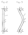
- Figure 2 shows a section through the wall construction used in the explosion chamber according to Figure 1, in the undeformed state.
- Figure 3 shows a section through the wall construction according to the invention in the deformed state.
- Figure 4 shows an enlarged detail of the deformed wall construction according to Figure 3.
- The explosion chamber 1 shown in Figure 1 has a
wall construction 2 according to the invention that is welded all round to adjoining structural components, which are constructed aswalls 3. The explosion chamber also has an access door, which is not shown, as well as other facilities that are required with such a chamber. - As is shown in Figure 2, the wall construction according to the invention has a wall panel 4, to the inside of which reinforcing bars, for example T-bars 5, are welded in the customary manner.
- Stop
elements 6 according to the invention are fitted on the outside of the wall panel. Thesestop elements 6 are welded to the adjoiningstructural components 3 and have a curved supportingface 7. - As soon as an explosion occurs in the explosion chamber, high pressure is exerted on the wall panel 4 causing it to deform into the state shown in Figure 3. The reinforcing bars 5 also deform. The wall panel 4 is able to absorb substantial forces in this deformed state since it is exposed to membrane stresses in its surface. As it is known, a panel is well able to withstand such membrane stresses. In addition, the support bars 5 of course have a supporting function.
- As can readily be seen in the detail in Figure 4, the wall panel 4 has come into contact with the supporting
face 7 ofstop element 6 during deformation. In this context the curvature of said supportingface 7 has been so chosen that the wall panel 4 has been gradually bent outwards from theweld 8. As a result excessive flexural stresses, especially in the outermost fibres of the wall panel 4, are avoided. It is also important that theweld 8 is hardly exposed to flexural stresses, as a result of which the risk of failure of the weld is largely prevented. - The advantage of the wall construction of the invention is that the
stop elements 6 can easily be fitted to an exiting explosion chamber at a later date. In this context it is necessary only to weld thesupport elements 6 to the structural components adjoining the wall panel 4, such as thewalls 3.
Claims (6)
- Wall construction with increased resistance to overpressure, such as overpressure as a consequence of explosions, which wall construction forms part of an explosion chamber and comprises an essentially flat wall panel (4), adjoining structural components (3) and at least one stop element (6), the wall panel (4) and the at least one stop element (6) being welded to the adjoining structural components (3), said at least one stop element (6) having a supporting face (7) facing the wall panel (4), characterized in that said supporting face can be brought into interaction with the wall panel (4) on deformation of the wall panel (4) under the influence of an overpressure on that side thereof that faces away from the stop element (6) and in that the at least one stop element (6) is formed as a stop block which only covers an edge area of the wall panel (4) and contacts said wall panel.
- Wall construction according to Claim 1, wherein the stop element (6) is located some distance away from the wall panel (4), the contact between the stop element (6) and the wall panel (4) being realized by filler plates.
- Wall construction according to Claim 1 or 2, wherein starting from the contact between stop element (6) and wall panel (4) away from the structural component adjoining said stop element (6) an increasing opening is present between the supporting face (7) of the stop element (6) and the as yet undeformed wall panel (4).
- Wall construction according to Claim 3, wherein the supporting face (7) of the stop element (6) is curved.
- Wall construction according to one of the preceding claims, wherein the stop element (6) has a recess such that the supporting face (7) terminates some distance away from the adjoining structural component (3).
- Wall construction according to one of the preceding claims, wherein multiple stop elements are provided regular distances apart.
Applications Claiming Priority (3)
| Application Number | Priority Date | Filing Date | Title |
|---|---|---|---|
| NL1013795 | 1999-12-08 | ||
| NL1013795A NL1013795C2 (en) | 1999-12-08 | 1999-12-08 | Explosion-proof wall construction. |
| PCT/NL2000/000910 WO2001042578A1 (en) | 1999-12-08 | 2000-12-08 | Explosion-resistant wall construction |
Publications (2)
| Publication Number | Publication Date |
|---|---|
| EP1235963A1 EP1235963A1 (en) | 2002-09-04 |
| EP1235963B1 true EP1235963B1 (en) | 2006-10-18 |
Family
ID=19770394
Family Applications (1)
| Application Number | Title | Priority Date | Filing Date |
|---|---|---|---|
| EP00991314A Expired - Lifetime EP1235963B1 (en) | 1999-12-08 | 2000-12-08 | Explosion-resistant wall construction |
Country Status (8)
| Country | Link |
|---|---|
| US (1) | US6971207B2 (en) |
| EP (1) | EP1235963B1 (en) |
| AT (1) | ATE343025T1 (en) |
| AU (1) | AU3241701A (en) |
| DE (1) | DE60031438T2 (en) |
| ES (1) | ES2273747T3 (en) |
| NL (1) | NL1013795C2 (en) |
| WO (1) | WO2001042578A1 (en) |
Families Citing this family (2)
| Publication number | Priority date | Publication date | Assignee | Title |
|---|---|---|---|---|
| CN1313687C (en) * | 2004-03-09 | 2007-05-02 | 刘义杰 | Making method of anti-earthquack well |
| EP2538167A1 (en) * | 2011-06-23 | 2012-12-26 | Nederlandse Organisatie voor toegepast -natuurwetenschappelijk onderzoek TNO | Blast and fragment resistant wall sections used inside structures like ships |
Family Cites Families (9)
| Publication number | Priority date | Publication date | Assignee | Title |
|---|---|---|---|---|
| US1066018A (en) * | 1912-12-17 | 1913-07-01 | Vergne Machine Company De | Ice-can. |
| US3360207A (en) * | 1965-04-21 | 1967-12-26 | Jr Harry J Shelton | Hammermills |
| US3758870A (en) * | 1972-02-23 | 1973-09-11 | Sanders Associates Inc | Digital demodulator |
| US3904524A (en) * | 1973-06-11 | 1975-09-09 | Advanced Fibre Glass Ltd | Container structure |
| SE439687B (en) | 1983-10-20 | 1985-06-24 | Bofors Ab | SPRENGKAMMARE |
| WO1989011007A1 (en) * | 1988-05-13 | 1989-11-16 | Vvs-Sord A/S | Pressure relief panel |
| AUPP166198A0 (en) * | 1998-02-06 | 1998-02-26 | Cyplex Pty Limited | Reinforcing member for containers |
| US6187451B1 (en) * | 1998-10-14 | 2001-02-13 | Her Majesty The Queen In Right Of Canada, As Represented By The Solicitor General Acting Through The Commissioner Of The Royal Canadian Mounted Police | Welded joint for armored vehicles |
| US6698709B2 (en) * | 2001-02-23 | 2004-03-02 | Western Forms, Inc. | Concrete forming panel with lightweight frame |
-
1999
- 1999-12-08 NL NL1013795A patent/NL1013795C2/en not_active IP Right Cessation
-
2000
- 2000-12-08 EP EP00991314A patent/EP1235963B1/en not_active Expired - Lifetime
- 2000-12-08 AU AU32417/01A patent/AU3241701A/en not_active Abandoned
- 2000-12-08 DE DE60031438T patent/DE60031438T2/en not_active Expired - Lifetime
- 2000-12-08 US US10/149,346 patent/US6971207B2/en not_active Expired - Fee Related
- 2000-12-08 WO PCT/NL2000/000910 patent/WO2001042578A1/en not_active Ceased
- 2000-12-08 ES ES00991314T patent/ES2273747T3/en not_active Expired - Lifetime
- 2000-12-08 AT AT00991314T patent/ATE343025T1/en not_active IP Right Cessation
Also Published As
| Publication number | Publication date |
|---|---|
| WO2001042578A1 (en) | 2001-06-14 |
| EP1235963A1 (en) | 2002-09-04 |
| DE60031438D1 (en) | 2006-11-30 |
| NL1013795C2 (en) | 2001-06-11 |
| US20040035076A1 (en) | 2004-02-26 |
| ES2273747T3 (en) | 2007-05-16 |
| AU3241701A (en) | 2001-06-18 |
| US6971207B2 (en) | 2005-12-06 |
| ATE343025T1 (en) | 2006-11-15 |
| DE60031438T2 (en) | 2007-09-20 |
Similar Documents
| Publication | Publication Date | Title |
|---|---|---|
| EP0404266A1 (en) | Bushing | |
| US4953734A (en) | Cabin-like cover especially for covering a machine | |
| RU2297500C2 (en) | Wall aperture fire barrier with cable leading-in frames | |
| GB2103780A (en) | Radiator | |
| US20040035076A1 (en) | Explosion-resistant wall construction | |
| US20020083672A1 (en) | Ceiling panel | |
| CN107949682A (en) | Fire and blast door assembly and method of installation | |
| CN212614397U (en) | Fireproof door plate and fireproof door structure | |
| KR20200127830A (en) | Bracket for connecting truss by non-welding scheme | |
| US4495147A (en) | Heat-retarding closure system for pressure relief openings of partitions, in nuclear reactor buildings | |
| JPS62111072A (en) | Structure and method for connecting side panel in unit room | |
| GB2277943A (en) | Blast-proof wall comprising panels and connectors | |
| EP0496187A1 (en) | Section member assembly for making continuous building glazed walls | |
| GB2315288A (en) | Explosion-resistant wall | |
| WO2004031498A1 (en) | Arrangement for forming a joint between a beam and a console | |
| WO2004056677A1 (en) | Prefabricated water tank having internal/external reinforcement structure | |
| KR102261879B1 (en) | Apparatus of fire door | |
| KR200380131Y1 (en) | Sandwich panel | |
| EP0554203A1 (en) | Modular system for building facades | |
| RU2099802C1 (en) | Building | |
| CN214087219U (en) | Elevator guide rail bracket | |
| US5761859A (en) | Interconnected door jamb brick | |
| KR200490971Y1 (en) | Support bracket for door pivot hinge | |
| JPH021275Y2 (en) | ||
| JP4008117B2 (en) | Wall panel mounting structure |
Legal Events
| Date | Code | Title | Description |
|---|---|---|---|
| PUAI | Public reference made under article 153(3) epc to a published international application that has entered the european phase |
Free format text: ORIGINAL CODE: 0009012 |
|
| 17P | Request for examination filed |
Effective date: 20020605 |
|
| AK | Designated contracting states |
Kind code of ref document: A1 Designated state(s): AT BE CH CY DE DK ES FI FR GB GR IE IT LI LU MC NL PT SE TR |
|
| AX | Request for extension of the european patent |
Free format text: AL;LT;LV;MK;RO;SI |
|
| GRAP | Despatch of communication of intention to grant a patent |
Free format text: ORIGINAL CODE: EPIDOSNIGR1 |
|
| GRAS | Grant fee paid |
Free format text: ORIGINAL CODE: EPIDOSNIGR3 |
|
| GRAA | (expected) grant |
Free format text: ORIGINAL CODE: 0009210 |
|
| AK | Designated contracting states |
Kind code of ref document: B1 Designated state(s): AT BE CH CY DE DK ES FI FR GB GR IE IT LI LU MC NL PT SE TR |
|
| PG25 | Lapsed in a contracting state [announced via postgrant information from national office to epo] |
Ref country code: CH Free format text: LAPSE BECAUSE OF FAILURE TO SUBMIT A TRANSLATION OF THE DESCRIPTION OR TO PAY THE FEE WITHIN THE PRESCRIBED TIME-LIMIT Effective date: 20061018 Ref country code: LI Free format text: LAPSE BECAUSE OF FAILURE TO SUBMIT A TRANSLATION OF THE DESCRIPTION OR TO PAY THE FEE WITHIN THE PRESCRIBED TIME-LIMIT Effective date: 20061018 Ref country code: FI Free format text: LAPSE BECAUSE OF FAILURE TO SUBMIT A TRANSLATION OF THE DESCRIPTION OR TO PAY THE FEE WITHIN THE PRESCRIBED TIME-LIMIT Effective date: 20061018 Ref country code: AT Free format text: LAPSE BECAUSE OF FAILURE TO SUBMIT A TRANSLATION OF THE DESCRIPTION OR TO PAY THE FEE WITHIN THE PRESCRIBED TIME-LIMIT Effective date: 20061018 |
|
| REG | Reference to a national code |
Ref country code: GB Ref legal event code: FG4D |
|
| REG | Reference to a national code |
Ref country code: CH Ref legal event code: EP Ref country code: IE Ref legal event code: FG4D |
|
| REF | Corresponds to: |
Ref document number: 60031438 Country of ref document: DE Date of ref document: 20061130 Kind code of ref document: P |
|
| PG25 | Lapsed in a contracting state [announced via postgrant information from national office to epo] |
Ref country code: IE Free format text: LAPSE BECAUSE OF NON-PAYMENT OF DUE FEES Effective date: 20061208 |
|
| PG25 | Lapsed in a contracting state [announced via postgrant information from national office to epo] |
Ref country code: MC Free format text: LAPSE BECAUSE OF NON-PAYMENT OF DUE FEES Effective date: 20061231 |
|
| PG25 | Lapsed in a contracting state [announced via postgrant information from national office to epo] |
Ref country code: DK Free format text: LAPSE BECAUSE OF FAILURE TO SUBMIT A TRANSLATION OF THE DESCRIPTION OR TO PAY THE FEE WITHIN THE PRESCRIBED TIME-LIMIT Effective date: 20070118 Ref country code: SE Free format text: LAPSE BECAUSE OF FAILURE TO SUBMIT A TRANSLATION OF THE DESCRIPTION OR TO PAY THE FEE WITHIN THE PRESCRIBED TIME-LIMIT Effective date: 20070118 |
|
| PG25 | Lapsed in a contracting state [announced via postgrant information from national office to epo] |
Ref country code: PT Free format text: LAPSE BECAUSE OF FAILURE TO SUBMIT A TRANSLATION OF THE DESCRIPTION OR TO PAY THE FEE WITHIN THE PRESCRIBED TIME-LIMIT Effective date: 20070319 |
|
| REG | Reference to a national code |
Ref country code: CH Ref legal event code: PL |
|
| REG | Reference to a national code |
Ref country code: ES Ref legal event code: FG2A Ref document number: 2273747 Country of ref document: ES Kind code of ref document: T3 |
|
| ET | Fr: translation filed | ||
| PLBE | No opposition filed within time limit |
Free format text: ORIGINAL CODE: 0009261 |
|
| STAA | Information on the status of an ep patent application or granted ep patent |
Free format text: STATUS: NO OPPOSITION FILED WITHIN TIME LIMIT |
|
| 26N | No opposition filed |
Effective date: 20070719 |
|
| PG25 | Lapsed in a contracting state [announced via postgrant information from national office to epo] |
Ref country code: GR Free format text: LAPSE BECAUSE OF FAILURE TO SUBMIT A TRANSLATION OF THE DESCRIPTION OR TO PAY THE FEE WITHIN THE PRESCRIBED TIME-LIMIT Effective date: 20070119 |
|
| PG25 | Lapsed in a contracting state [announced via postgrant information from national office to epo] |
Ref country code: TR Free format text: LAPSE BECAUSE OF FAILURE TO SUBMIT A TRANSLATION OF THE DESCRIPTION OR TO PAY THE FEE WITHIN THE PRESCRIBED TIME-LIMIT Effective date: 20061018 Ref country code: LU Free format text: LAPSE BECAUSE OF NON-PAYMENT OF DUE FEES Effective date: 20061208 |
|
| PG25 | Lapsed in a contracting state [announced via postgrant information from national office to epo] |
Ref country code: CY Free format text: LAPSE BECAUSE OF FAILURE TO SUBMIT A TRANSLATION OF THE DESCRIPTION OR TO PAY THE FEE WITHIN THE PRESCRIBED TIME-LIMIT Effective date: 20061018 |
|
| PGFP | Annual fee paid to national office [announced via postgrant information from national office to epo] |
Ref country code: GB Payment date: 20121220 Year of fee payment: 13 Ref country code: IT Payment date: 20121221 Year of fee payment: 13 |
|
| PGFP | Annual fee paid to national office [announced via postgrant information from national office to epo] |
Ref country code: DE Payment date: 20121220 Year of fee payment: 13 Ref country code: ES Payment date: 20121226 Year of fee payment: 13 Ref country code: BE Payment date: 20121219 Year of fee payment: 13 Ref country code: FR Payment date: 20130130 Year of fee payment: 13 |
|
| PGFP | Annual fee paid to national office [announced via postgrant information from national office to epo] |
Ref country code: NL Payment date: 20121220 Year of fee payment: 13 |
|
| BERE | Be: lapsed |
Owner name: NEDERLANDSE ORGANISATIE VOOR TOEGEPAST-NATUURWETE Effective date: 20131231 |
|
| REG | Reference to a national code |
Ref country code: DE Ref legal event code: R119 Ref document number: 60031438 Country of ref document: DE |
|
| REG | Reference to a national code |
Ref country code: NL Ref legal event code: V1 Effective date: 20140701 |
|
| GBPC | Gb: european patent ceased through non-payment of renewal fee |
Effective date: 20131208 |
|
| REG | Reference to a national code |
Ref country code: FR Ref legal event code: ST Effective date: 20140829 |
|
| REG | Reference to a national code |
Ref country code: DE Ref legal event code: R119 Ref document number: 60031438 Country of ref document: DE Effective date: 20140701 |
|
| PG25 | Lapsed in a contracting state [announced via postgrant information from national office to epo] |
Ref country code: BE Free format text: LAPSE BECAUSE OF NON-PAYMENT OF DUE FEES Effective date: 20131231 Ref country code: NL Free format text: LAPSE BECAUSE OF NON-PAYMENT OF DUE FEES Effective date: 20140701 Ref country code: DE Free format text: LAPSE BECAUSE OF NON-PAYMENT OF DUE FEES Effective date: 20140701 |
|
| PG25 | Lapsed in a contracting state [announced via postgrant information from national office to epo] |
Ref country code: GB Free format text: LAPSE BECAUSE OF NON-PAYMENT OF DUE FEES Effective date: 20131208 Ref country code: FR Free format text: LAPSE BECAUSE OF NON-PAYMENT OF DUE FEES Effective date: 20131231 |
|
| REG | Reference to a national code |
Ref country code: ES Ref legal event code: FD2A Effective date: 20150330 |
|
| PG25 | Lapsed in a contracting state [announced via postgrant information from national office to epo] |
Ref country code: ES Free format text: LAPSE BECAUSE OF NON-PAYMENT OF DUE FEES Effective date: 20131209 |
|
| PG25 | Lapsed in a contracting state [announced via postgrant information from national office to epo] |
Ref country code: IT Free format text: LAPSE BECAUSE OF NON-PAYMENT OF DUE FEES Effective date: 20131231 |
|
| PG25 | Lapsed in a contracting state [announced via postgrant information from national office to epo] |
Ref country code: IT Free format text: LAPSE BECAUSE OF NON-PAYMENT OF DUE FEES Effective date: 20131208 |