EP1235447A2 - Radio communication apparatus and qualification method of the same - Google Patents
Radio communication apparatus and qualification method of the same Download PDFInfo
- Publication number
- EP1235447A2 EP1235447A2 EP02251336A EP02251336A EP1235447A2 EP 1235447 A2 EP1235447 A2 EP 1235447A2 EP 02251336 A EP02251336 A EP 02251336A EP 02251336 A EP02251336 A EP 02251336A EP 1235447 A2 EP1235447 A2 EP 1235447A2
- Authority
- EP
- European Patent Office
- Prior art keywords
- radio
- radio communication
- test
- resource
- qualification
- Prior art date
- Legal status (The legal status is an assumption and is not a legal conclusion. Google has not performed a legal analysis and makes no representation as to the accuracy of the status listed.)
- Granted
Links
Images


Classifications
-
- H—ELECTRICITY
- H04—ELECTRIC COMMUNICATION TECHNIQUE
- H04W—WIRELESS COMMUNICATION NETWORKS
- H04W24/00—Supervisory, monitoring or testing arrangements
Definitions
- the present invention relates to a qualification method (an authorization method) of a radio communication apparatus capable of changing radio functions.
- radio communication apparatus such as portable telephones and PHS (Personal Handyphone System) telephones are designed and manufactured based upon modulation systems and transfer rates. Further, the modulation systems and transfer rates arc exclusively used by these radio communication apparatus, and are defined in accordance with technical standards/specifications. In other words, a conventional radio terminal can only be used in a single radio communication system. Further, to use the conventional terminal, a qualification test is first performed. The qualification test is different than a performance test, which is performed for all radio terminal products when they are shipped from a factory of a manufacturer. On the contrary, the qualification test utilizes or determines whether or not the transmission technical specifications of the relevant radio terminal can be defined under the regulations of law.
- a radio terminal is tested while it is being prepared, A qualification test radio communication system is also set up in which the tested radio terminal can transmit and receive.
- the qualification test performs various tests, such as frequency deviation, deviation of antenna power, and spurious radiation strengths.
- a measurement is performed using both a measuring device and a corresponding method, which are determined for every feature tested.
- a result of the measurement is then compared with the technical standards of the radio communication system. For example, an allowable deviation in a frequency deviation test of a PHS radio communication system is within the exclusive range + 3 x 10 -6 and - 3 x 10 -6 . Further, an upper limit of allowable antenna power deviation is 20% of the rated power, and a lower limit is 50% of the rated power.
- the tested radio terminal When the measurement results of each feature tested (e.g., frequency deviation, antenna power deviation, etc.) satisfy the technical standards, the tested radio terminal is considered to have passed the qualification test. On the contrary, if the radio terminal does not satisfy the technical standards, the tested radio is considered to have failed the qualification test.
- the measurement results of each feature tested e.g., frequency deviation, antenna power deviation, etc.
- a radio terminal including software for performing radio functions is hereinafter referred to as a "software-defined radio (SDR) terminal.”
- the following problems occur when a qualification test is performed on a software-defined radio terminal.
- a modulating/demodulating process operation and a coding system are processed using software, and the software-defined radio machine can transmit and receive radio signals within several different radio communication systems.
- the software-defined radio terminal passes a qualification for a first radio communication system, if the software of another radio communication system is installed (downloaded) onto the software-defined radio terminal, the software-defined radio terminal will likely not be able to communicate within the second radio communication system.
- the software-defined radio terminal may generate electromagnetic waves having a higher electric power higher than required by law and/or may cause power leakage to adjacent channels.
- one object of the present invention is to solve the above-noted and other problems.
- Another object of the present invention is to provide a highly efficient qualification testing method of a software-defined radio machine that does not have to be performed for each software-defined radio terminal.
- the present invention provides a qualification method for testing a radio communication system including a plurality of radio terminals.
- the method includes providing a representative terminal having a machine type identical to a machine type of the plurality of radio terminals, and executing a qualification test on the representative terminal so as to determine whether or not the representative terminal can be used in a desired radio communication system from a plurality of radio communication systems.
- the method also includes receiving a test success message indicating that the representative terminal passed the qualification test, and notifying the test success message to the plurality of radio terminals.
- the present invention also relates to a computer program product and apparatus for performing the qualification test.
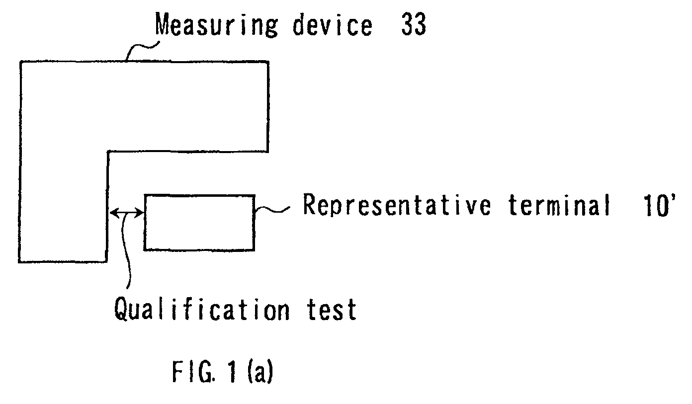
- Fig. 1 illustratively indicates a conceptional idea of a qualification method in accordance with an embodiment of the present invention.
- a measuring device 33 performs a qualification test for a desirable radio communication system with respect to a representative terminal 10'.
- the machine type of the representative terminal 10' is identical to a radio terminal 10 (see Fig. 1(b)) for which a qualification test is to be performed. That is, if the representative terminal 10' passes the qualification test, it is assumed the radio terminal 10 can also pass the qualification test.
- a test success notifying device for example, base station
- transmits notifies
- a test success message notification
- the radio terminal 10 can receive a radio signal any time.
- the radio terminal 10 may utilize the above-described desirable radio communication system.
- utilization of a radio communication system implies that in response to the notification issued from the test success notifying device, the radio terminal 10 may transmit to the desirable radio communication system.
- An example of a test success notification is when the radio terminal 10 receives a data flag "qualification OK (okay)" implying the radio terminal 10 is allowed to transmit to the desirable radio communication system.
- test success notifying device implies a service center and the like may notify a test success message to the radio terminal 10 in a wireless communication manner, or a wire communication manner.
- Fig. 2 is a schematic block diagram showing a major unit of the radio terminal 10,10' shown in Figs. 1(a) and 1(b).
- the radio terminal 10 is equipped with an antenna 16, a radio unit 11, a resource 12, a resource controller 13, a storage apparatus 14, and a radio unit controller 15.
- the radio unit 11 executes a wireless communication with respect to another radio terminal (not shown).
- the resource 12 includes a function for performing a modulating/demodulating process operation, and another function for executing a signal process operation with respect to data.
- the resource controller 13 manages the resource 12, the storage apparatus 14 reads/writes data with respect to the resource 12, and the radio unit controller 15 controls the radio unit 11.
- Fig. 2 illustrates, for the sake of a simple explanation, only the major signal flows of analog and digital signals, and detailed control signal lines are omitted.
- the radio unit 11 Under control of the radio unit controller 15, the radio unit 11 converts a frequency of an electromagnetic wave received by the antenna 16 into a digital signal. The radio unit 11 then supplies the digital signal to the resource 12 provided with the signal processing function which is resettable. On the other hand, under control of the radio unit controller 15, the radio unit 11 receives transmission data which is produced by the resource 12, converts this transmission data into an analog signal, and converts the analog signal into a high frequency (radio frequency) signal so as to transmit the high frequency signal as an electromagnetic wave.
- the resource 12 includes functions for executing the modulating/demodulating operation and the signal process operation with respect to the data.
- the resource 12 executes the demodulating process operation with respect to an analog signal supplied from the radio unit 11 so as to derive data from this analog signal based on the provided function.
- the resource 12 executes the demodulating process operation with respect to transmission data, and supplies the demodulated signal to the radio unit 11.
- the radio unit controller 15 and the resource 12 receives the success notification message indicating "qualification OK.”
- the radio unit 11 can then transmit to a radio communication system by at least any one of the radio unit controller 15 and the resource 12.
- the resource controller 13 changes a setting operation of the function of the resource 12 based upon information indicative of a structure of a resource (not shown).
- the storage apparatus 14 stores a software program capable of realizing the function provided on the resource 12 and data as to a circuit arrangement of a DSP (Digital Signal Processor) and an FPGA (Field Programmable Gate Array), which will be explained later.
- the storage apparatus 14 also stores control parameter data corresponding to a radio function variable element (discussed later with respect to Fig. 5), and data corresponding to either a received signal or a signal to be transmitted.
- the storage apparatus 14 includes a hard disk unit and/or a semiconductor memory, for example.
- the function for performing the signal process operation with respect to the data is resettable.
- a resource corresponds to an apparatus for executing a signal processing operation.
- the resource may be a digital signal processor (DSP), a rewritable logic (FPGA, Field Programmable Gate Array), or the like. Because either a DSP or an FPGA is used, a desirable function block may be allocated in a flexible manner.
- Fig. 3 is a schematic block diagram indicating an arrangement of the resource controller 13 shown in Fig. 2.
- the resource controller 13 includes a resource management table 21, a resource manager 22, and a resource changing device 23.
- the resource manager 22 updates contents of the resource management table 21 in response to use states of resources owned in the radio tenninal 10. As a result, the remaining resources may be allocated by using the resource management table 21.
- the resource manager 22 allocates the required amount of resources to realize a desirable function based upon information indicative of an arrangement used to realize a newly added function. Furthermore, the resource manager 22 executes an allocation of these resources using the information as to the remaining resource. A function of a resource is also changed by the resource changing device 23.
- such a radio terminal capable of changing the radio function based upon the information (resource 12) indicative of the structure of the radio function can be realized.
- Fig. 4 is a schematic block diagram of the measuring device 33 shown in Fig. 1.
- a radio communication apparatus 31 to be tested corresponds to the representative terminal 10' of Fig. 1.
- a test program 32 corresponds to a program installed in a memory of the measuring device 33 and is used to test the radio communication apparatus 31.
- the test program 32 includes software for testing the modulating/demodulating and detecting process operations for every predetermined radio communication system, Further, the test program 32 is processed in the form of a library.
- the radio communication system provided in the software-defined radio terminal maybe changed. Therefore, the test program is prepared for every radio communication system to be tested by a qualification test. A test feature is also determined for every predetermined radio communication system.
- the following qualification test features maybe provided for a PHS system: frequency deviation; deviation in antenna power, strengths of spurious radiation; occupied bandwidths; adjacent channel leakage power; leakage power under carrier-OFF condition; transmission speeds of modulation signals; strengths of electromagnetic waves which are secondarily generated and so on.
- the measuring device 33 configured to perform the qualification test includes the test program 32, a controller 34, and a definition information resource 35 corresponding to resources used in the tested radio communication apparatus 31.
- a test operation of the radio communication apparatus 31 is performed as follows:
- the structure of the resource of the radio communication apparatus 31 is changed based upon the definition information resource 35 indicative of the resources used in the radio communication apparatus 31, and the test program 32 is executed.
- a characteristic of a radio terminal may depend upon an arrangement of the internal radio functions, measuring operations should be performed plural times corresponding to the different radio functions. Therefore, the controller 34 performs the test operation while sequentially changing both the definition information resource 35 indicative of the structure of the resource and the test program 32. If all tested features satisfy the technical standards, then the radio communication apparatus 31 is considered to have passed the qualification test. On the contrary, if all of tested features are not satisfied, the apparatus 31 is considered to have failed the test
- radio functions there are several types of radio functions provided in a software-defined radio terminal.
- software modules corresponding to a plurality of different radio communication systems arc loaded onto the software-defined radio terminal. Accordingly, a qualification test should be performed for all combinations in which plural radio communication systems maybe commonly present.
- the controller 34 deletes a software program used for system A, which is stored in the radio communication apparatus 31 (i.e., an initializing operation is performed so the apparatus 31 doesn't have any software programs installed).
- the controller 34 selects the appropriate resource definition information so only system A will be loaded on the radio communication apparatus 31 from the resource definition information 35.
- the controller 34 transmits (downloads) the selected resource definition information to the radio communication apparatus 31.
- a test program used for system A is executed, thereby completing a qualification test when only system A is to be tested.
- the controller 34 subsequently deletes the software program used for system A from the radio communication apparatus 31, and initializes the radio communication apparatus 31.
- the controller 34 selects the appropriate resource definition information for system B, and transmits the selected resource definition information to the radio communication apparatus 31. Thereafter, a test program used for the system B is executed, so as to perform a qualification test for system B. The other combinations may be similarly tested.
- test program 32 used to test a plurality of test features and the resource definition information 35 indicative of the arrangement of the resource of the radio communication apparatus are defined as a library, the qualification test of the software-defined radio terminal can be easily realized.
- mass-produced radio terminals with the same machine type include equivalent functions.
- qualification tests may be performed only on a smaller group of the mass-produced radio terminals so as to reduce the complexity and time required to complete the testing process for all of the mass-produced radio terminals.
- Fig. 5 is a block diagram of the radio unit 11 shown in Fig. 2.
- a digital signal transferred from a digital signal processing unit employed in the resource 12 of Fig. 2 is converted into an analog signal by a digital-to-analog converter (DAC), and the analog signal output from the DAC is passed through a low-pass filter (LPF1).
- a signal output from the LPF1 is then mixed with a signal output from an oscillator 1 by a mixer so as to be frequency-converted.
- a signal output from the mixer is supplied to a band-pass filter (BPF1), and a signal output from the BPF1 is amplified by an amplifier (AMP1).
- BPF1 band-pass filter
- AMP1 amplifier
- a signal output from the AMP1 is mixed with a signal output from another oscillator 2 by another mixer so as to be frequency-converted.
- the frequency-converted signal is then supplied to another band-pass filter (BPF2), and the filtered signal is amplified by another amplifier (AMP2).
- BPF2 band-pass filter
- AMP2 amplifier
- a signal output from the AMP2 is radiated from the antenna 16 through a circulator 17.
- a signal received by the antenna 16 is supplied via the circulator 17 to another amplifier (AMP3).
- a signal flow operation executed when a signal is received is performed in accordance with a sequential operation indicated by the arrows in the lower half of Fig. 5.
- Fig. 5 merely indicates one example of a signal flow operation, but does not limit the radio unit 11.
- Fig. 5 merely represents as one example, a total number of the amplifiers, oscillators, and filters. However, any other number of components (amplifiers, oscillators, filters, etc.) may be used.
- a radio function variable element 41 includes the DAC, oscillator, AMP, and ADC, which is variable in response to a control parameter
- a control line 40 (indicated by a dotted line) connects the radio function variable element 41 with the radio unit controller 15.
- the radio unit controller 15 changes the control parameter of the radio function variable element 41 using the control line 40 so as to control the radio unit 11 in such a manner that the radio terminal may be adapted to a desirable radio communication system.
- This control operation implies that, for example, a bit extracting position of the DAC is controlled, an oscillation frequency of an oscillator is controlled, an amplification of an AMP is controlled and so on. Then, when the qualification test is performed, the measuring device 33 of Fig. 4 executes the qualification test while the measuring device 33 controls the radio unit controller 15 via the definition information resource 35.
- a software-defined radio terminal is properly operable with respect to a plurality of radio communication systems.
- the radio unit 11 is required to operate with respect to all radio communication systems. In this instance, it is not possible to avoid a condition in which the technical specification of the radio unit 11 more or less exceeds the standard technical specifications.
- the radio unit 11 is arranged so it may be controlled by the above-explained radio unit controller 15, the radio function of the radio unit 11 may be appropriately changed via the radio unit controller 15.
- Fig. 6 is a timing diagram representing an example of a control signal which is transferred to the radio function variable element 41 via the control line 40 by the radio unit controller 15.
- a gate circuit converts a clock signal produced by frequency-dividing a system clock into the control signal.
- Fig. 6 illustrates, as an example, control signals having different rise times (i.e., patterns 1, 2, and 3).
- the control signal is supplied to, for example, an amplifier of a radio unit so as to be used for a control operation of transmitting a desirable signal.
- a characteristic of an analog radio unit may greatly depend upon a control method of the analog radio unit. In other words, the characteristic of the analog radio unit maybe changed based on how the analog radio unit is controlled.
- Fig. 7 represents both spectra and time response waveforms of modulation signals amplified by an amplifier in the radio function variable element 41.
- symbols (a-1) and (b-1) indicate the spectra of the modulation signals
- symbols (a-2) and (b-2) represent the time response waveforms.
- the spectrum (b-1) corresponds to a time response waveform that is changed in a step form
- the spectrum (a-1) corresponds to a time response waveform that is gently changed, similar to a ramp function.
- the adjacent channel leakage power is changed, depending upon the control method used by the analog radio unit.
- Fig. 8 schematically indicates another example of how the characteristic of the analog radio unit may be changed, based on a change in the control method (i.e., by modification ofAMP2 shown in Fig. 5).
- an output of a power amplifier PA 52 (corresponding to the AMP2 of Fig. 5) is connected to the antenna 16 via an analog switch SW 50.
- ON/OFF operations of the analog switch SW 50 is controlled by the radio unit controller 15.
- the OFF operation of only one analog switch SW may be used.
- the characteristic of the analog radio unit depend on the control method of the analog radio unit. In other words, there is a correlative relationship between the control method and the characteristic of the analog radio unit. Thus, when the control method of the radio unit is specified, the characteristic of the radio unit can also be specified.
- the qualification test of the radio communication apparatus can be readily achieved, and the radio functions of the radio communication apparatus can be easily changed based on information indicative of the structures of the radio functions.
- the controller 34 of the measuring device 33 transmits a message to a radio unit controller of a radio communication apparatus to be tested, then the appropriate qualification test may be easily performed even when a control method of a radio unit is changed (for example, a radio communication system is changed from system A to system B).
- Fig. 9 is an explanatory diagram for explaining an operation executed after the representative terminal passes the qualification test in Fig. 1(a), (i.e., a test success message is notified from a test success notifying device 100 to a radio terminal 10 as shown in Fig. 1(b)).
- the representative terminal namely, radio terminal 10' of Fig. 1 whose machine type is identical to that of the radio terminal 10 has passed a qualification test and the representative terminal is provided with a terminal function of a radio communication system operated by the test success notifying device 100 of Fig. 9.
- the test success notifying device 100 includes a database 101. Further, a control sequence of a radio unit with respect to each radio terminal used in the radio communication system is described in the database 101. The management of the database 101 is performed by a base station controller (not shown) installed in a test success notifying device 100 (for example, a base station).
- a radio function of the radio terminal 10 may be changed by changing a resource (namely, the resource 12 of Fig. 2).
- the radio terminal 10 acquires such information in a download operation, or the like so as to change the resource. Further, the acquired information indicates the terminal function of the radio communication system which is operated by the test success notifying device 100 of Fig. 9.
- the radio terminal 10 owns the terminal function of the radio communication system operated by the test success notifying device 100 of Fig. 9.
- the radio terminal 10 In order for the radio terminal 10 to radiate electromagnetic waves, the radio terminal 10 must pass a qualification test.
- the representative terminal namely, radio terminal 10' of Fig, 1 whose machine type is identical to that of the radio terminal 10 has passed the qualification test so the representative terminal 10' is provided with the terminal functions of the radio communication system operated by the test success notifying device 100 of Fig. 9.
- the radio terminal 10 shown in Fig. 9 executes a control sequence capable of passing a qualification test, then the radio terminal 10 passed the qualification test.
- the radio terminal 10 In order for the radio terminal 10 to execute the control sequence capable of passing the qualification test, the radio terminal 10 must acquire the information representative of this control sequence. When the radio terminal 10 has not yet acquired the control sequence capable of passing the qualification test, the radio terminal 10 cannot radiate electromagnetic waves (i.e., because it has not passed a qualification test).
- the radio terminal 10 cannot request the base station to provide the information indicative of the control sequence.
- regulation corresponding to radio signal receptions do not prevent the radio terminal 10 from receiving radio signals. Therefore, if the base station notifies in a periodic manner the control sequence of the analog radio unit whose machine type is identical to that of the representative terminal (namely, radio terminal 10' of Fig. 1), then the radio terminal 10 may acquire the information indicative of this control sequence.
- Fig. 10 is a diagram for illustratively showing a modification of the test success notification operation shown in Fig. 9.
- the radio terminal 10 communicates with different base stations (e.g., both base stations A and B) which are operated by a plurality of different radio communication systems (both radio communication system A and radio communication system),
- the radio terminal 10 may access both of the radio communication systems A and B in, for example, a time divisional manner and the like.
- the necessary function for connecting with the different radio communication systems has been set to the resource 12 of the radio terminal 10.
- the required control timing is very strict, as compared to a radio terminal 110 connected to only one radio communication system.
- the radio terminal 10 acquires the information indicative of a control sequence of an analog radio unit employed in the radio terminal 10 from the base stations, and controls the analog radio unit in accordance with this acquired information, so the radio terminal 10 may radiate electromagnetic waves.
- control sequences there is no limitation as to the number of control sequences. That is, only one control sequence of an analog radio unit used in a radio terminal is not provided in order to pass a qualification test. Therefore, if a plurality of control sequences are previously tested for the representative terminal (namely, the radio terminal 10' of Fig. 1) and the plurality of control sequences capable of passing a qualification test can be determined, then a radio terminal may select a suitable control sequence. In other words, for a radio terminal whose control timing is very strict, this radio terminal may select its own suitable control sequence suitable from the plurality of control sequences capable of passing a qualification test.
- the base station may notify the plurality of control sequences in a periodic manner.
- the strict control timing of the analog radio unit can be mitigated.
- the test result for indicating as to whether or not this representative radio terminal can pass this qualification test is applied via the test success notifying device to another radio terminal whose machine type is the same as the machine type of the representative radio terminal. Therefore, such a qualification test does not have to be performed for each radio terminal, so the total number of qualification tests is reduced. This is especially effective when a newly-introduced radio communication system is brought into service.
- This invention may be conveniently implemented using a conventional general purpose digital computer or microprocessor programmed according to the teachings of the present specification, as will be apparent to those skilled in the computer art Appropriate software coding can readily be prepared by skilled programmers based on the teachings of the present disclosure, as will be apparent to those skilled in the software art.
- the invention may also be implemented by the preparation of application specific integrated circuits or by interconnecting an appropriate network of conventional component circuits, as will be readily apparent to those skilled in the art.
- the present invention includes a computer program product which is a storage medium including instructions which can be used to program a computer to perform a process of the invention.
- the storage medium can include, but is not limited to, an type of disk including floppy disks, optical disks, CD-ROMs, and magneto-optical disks, ROMs, RAMs, EPROMs, EEPROMs, magnetic or optical cards, or any type of pure software inventions (e.g., word processing, accounting, Internet related, etc.) media suitable for storing electronic instructions
Landscapes
- Engineering & Computer Science (AREA)
- Computer Networks & Wireless Communication (AREA)
- Signal Processing (AREA)
- Mobile Radio Communication Systems (AREA)
- Monitoring And Testing Of Transmission In General (AREA)
- Small-Scale Networks (AREA)
- Maintenance And Management Of Digital Transmission (AREA)
- Telephone Function (AREA)
- Transceivers (AREA)
Abstract
Description
Claims (17)
- A qualification method for testing a radio communication system including a plurality of radio terminals (10), comprising:providing a representative terminal (10) having a machine type identical to a machine type of the plurality of radio terminals;executing a qualification test on the representative terminal so as to determine whether or not the representative terminal can be used in a desired radio communication system from a plurality of radio communication systems;receiving a test success message indicating that the representative terminal passed the qualification test; andnotifying the test success message to the plurality of radio terminals.
- A method according to claim 1, wherein
the executing step determines a control sequence for controlling a radio unit of the representative terminal, by which the representative terminal can pass the qualification test, and
the receiving step receives the control sequence from the measuring step, and the notifying step notifies the received control sequence to the plurality of radio terminals. - A method according to claim 1 or 2, wherein the notifying step notifies the plurality of radio terminals via a base station used for the desired radio communication system.
- A method according to claim 1 or 2, wherein the notifying step notifies the plurality of radio terminals via a service center used for the desired radio communication system.
- A method according to any one of claims 1 to claim 4, wherein the service center notifies the test success message to the plurality of radio terminals by wireless communication.
- A method according to any one of claims 1 to 4, wherein the service center notifies the test success message to the plurality of radio terminals by wire communication.
- A method according to any one of the preceding claims, wherein the executing step performs a qualification test for all combinations of the plurality of radio communication systems.
- A qualification system for testing a radio communication system including a plurality of radio terminals (10), and a representative terminal (10) having a machine type identical to a machine type of the plurality of radio terminals, the system comprising:means (33) for executing a qualification test on the representative terminal so as to determine whether or not the representative terminal can be used in a desired radio communication system from a plurality of radio communication systems;means for receiving a test success message indicating that the representative terminal passed the qualification test; andmeans (100) for notifying the test success message to the plurality of radio terminals.
- A system according to claim 8, wherein
the executing means determines a control sequence for controlling a radio unit of the representative terminal, by which the representative terminal can pass the qualification test, and
the receiving means receives the control sequence from the measuring step, and the notifying means notifies the received control sequence to the plurality of radio terminals. - A system according to claim 8 or 9 wherein the notifying means notifies the plurality of radio terminals via a base station used for the desired radio communication system.
- A system according to claim 8 or 9, wherein the notifying means notifies the plurality of radio terminals via a service center used for the desired radio communication system.
- A system according to any one of claims 8 to 11, wherein the service center notifies the test success message to the plurality of radio terminals by wireless communication.
- A system according to any one of claims 8 to 11, wherein the service center notifies the test success message to the plurality of radio terminals by wire communication.
- A system according to any one of claims 8 to 13, wherein the executing means performs a qualification test for all combinations of the plurality of radio communication systems.
- A radio communication apparatus, comprising:wherein the radio communication apparatus is configured to transmit signals within a desired radio communication system out of a plurality of radio communication systems, when the radio communication apparatus receives an externally transmitted message indicating that the radio communication apparatus may transmit signals with respect to the desired radio communication system.a radio unit (11) configured to convert an analog radio signal into a digital signal;a radio unit controller (15) configured to control the radio unit;a resource (12) configured to communicate the digital signal with the radio unit, to perform a signal processing operation on the digital signal, and to reset a function of the signal processing operation; anda resource controller (13) configured to manage the resource,
- An apparatus according to claim 15, wherein the resource controller comprises:a resource management table (21) indicating a surplus of the resource;a resource manager (22) configured to allocate the surplus of the resource; anda resource changing device (23) configured to change a function of the resource.
- An apparatus according to claim 15, further comprising:wherein the radio unit controller controls ON/OFF operations of the analog switch.an antenna (16) configured to transmit and receive radio signals; andan analog switch (SW) disposed between the antenna and a power amplifier (PA) of the radio unit,
Applications Claiming Priority (2)
| Application Number | Priority Date | Filing Date | Title |
|---|---|---|---|
| JP2001049869A JP3607208B2 (en) | 2001-02-26 | 2001-02-26 | Wireless terminal certification test system |
| JP2001049869 | 2001-02-26 |
Publications (3)
| Publication Number | Publication Date |
|---|---|
| EP1235447A2 true EP1235447A2 (en) | 2002-08-28 |
| EP1235447A3 EP1235447A3 (en) | 2003-04-23 |
| EP1235447B1 EP1235447B1 (en) | 2005-12-14 |
Family
ID=18910909
Family Applications (1)
| Application Number | Title | Priority Date | Filing Date |
|---|---|---|---|
| EP02251336A Expired - Lifetime EP1235447B1 (en) | 2001-02-26 | 2002-02-26 | Radio communication apparatus and qualification method of the same |
Country Status (5)
| Country | Link |
|---|---|
| US (1) | US20020119754A1 (en) |
| EP (1) | EP1235447B1 (en) |
| JP (1) | JP3607208B2 (en) |
| CN (1) | CN1372388A (en) |
| DE (1) | DE60207917T2 (en) |
Cited By (2)
| Publication number | Priority date | Publication date | Assignee | Title |
|---|---|---|---|---|
| EP1395074A1 (en) * | 2002-08-30 | 2004-03-03 | Siemens Aktiengesellschaft | Method for operation of a terminal in a radio communication system, radio communication system, terminal and confirmation unit for a radio communication system |
| US6954636B2 (en) | 2002-09-06 | 2005-10-11 | Kabushiki Kaisha Toshiba | Approval test method and an approval test system for a software-defined radio terminal, a software-defined radio terminal being certified by the approval test method, and an approval test apparatus for certifying the software-defined radio terminal |
Families Citing this family (31)
| Publication number | Priority date | Publication date | Assignee | Title |
|---|---|---|---|---|
| CN100440879C (en) * | 2001-01-25 | 2008-12-03 | 株式会社东芝 | Mobile wireless communication device adaptable to multiple wireless communication systems |
| WO2004042959A1 (en) | 2002-11-04 | 2004-05-21 | Vivato Inc | Directed wireless communication |
| GB0315931D0 (en) * | 2003-07-08 | 2003-08-13 | Koninkl Philips Electronics Nv | Radio device testing system |
| US7158583B2 (en) * | 2003-07-10 | 2007-01-02 | Sandbridge Technologies, Inc. | Multiple communication protocols with common sampling rate |
| US8463319B2 (en) * | 2005-06-17 | 2013-06-11 | Honeywell International Inc. | Wireless application installation, configuration and management tool |
| KR100585577B1 (en) * | 2005-11-30 | 2006-06-07 | 주식회사 퓨전소프트 | Test method of wireless communication terminal based on automatic creation of test scenario file |
| JP5588524B2 (en) * | 2012-02-13 | 2014-09-10 | アンリツ株式会社 | Measuring apparatus and measuring method |
| US12356206B2 (en) | 2013-03-15 | 2025-07-08 | Digital Global Systems, Inc. | Systems and methods for automated financial settlements for dynamic spectrum sharing |
| US11646918B2 (en) | 2013-03-15 | 2023-05-09 | Digital Global Systems, Inc. | Systems, methods, and devices for electronic spectrum management for identifying open space |
| US8750156B1 (en) | 2013-03-15 | 2014-06-10 | DGS Global Systems, Inc. | Systems, methods, and devices for electronic spectrum management for identifying open space |
| US10257728B2 (en) | 2013-03-15 | 2019-04-09 | DGS Global Systems, Inc. | Systems, methods, and devices for electronic spectrum management |
| US10257729B2 (en) | 2013-03-15 | 2019-04-09 | DGS Global Systems, Inc. | Systems, methods, and devices having databases for electronic spectrum management |
| US10299149B2 (en) | 2013-03-15 | 2019-05-21 | DGS Global Systems, Inc. | Systems, methods, and devices for electronic spectrum management |
| US9078162B2 (en) | 2013-03-15 | 2015-07-07 | DGS Global Systems, Inc. | Systems, methods, and devices for electronic spectrum management |
| US10244504B2 (en) | 2013-03-15 | 2019-03-26 | DGS Global Systems, Inc. | Systems, methods, and devices for geolocation with deployable large scale arrays |
| US10219163B2 (en) | 2013-03-15 | 2019-02-26 | DGS Global Systems, Inc. | Systems, methods, and devices for electronic spectrum management |
| US12256233B2 (en) | 2013-03-15 | 2025-03-18 | Digital Global Systems, Inc. | Systems and methods for automated financial settlements for dynamic spectrum sharing |
| US10271233B2 (en) | 2013-03-15 | 2019-04-23 | DGS Global Systems, Inc. | Systems, methods, and devices for automatic signal detection with temporal feature extraction within a spectrum |
| US10231206B2 (en) | 2013-03-15 | 2019-03-12 | DGS Global Systems, Inc. | Systems, methods, and devices for electronic spectrum management for identifying signal-emitting devices |
| US10257727B2 (en) | 2013-03-15 | 2019-04-09 | DGS Global Systems, Inc. | Systems methods, and devices having databases and automated reports for electronic spectrum management |
| US10237770B2 (en) | 2013-03-15 | 2019-03-19 | DGS Global Systems, Inc. | Systems, methods, and devices having databases and automated reports for electronic spectrum management |
| EP3280075A1 (en) | 2016-08-03 | 2018-02-07 | Rohde & Schwarz GmbH & Co. KG | Measurement system and a method |
| US9955371B1 (en) * | 2017-01-04 | 2018-04-24 | Rohde & Schwarz Gmbh & Co. Kg | Method for testing a device under test, electronic device, and measurement unit |
| US12183213B1 (en) | 2017-01-23 | 2024-12-31 | Digital Global Systems, Inc. | Unmanned vehicle recognition and threat management |
| US10700794B2 (en) | 2017-01-23 | 2020-06-30 | Digital Global Systems, Inc. | Systems, methods, and devices for automatic signal detection based on power distribution by frequency over time within an electromagnetic spectrum |
| US10459020B2 (en) | 2017-01-23 | 2019-10-29 | DGS Global Systems, Inc. | Systems, methods, and devices for automatic signal detection based on power distribution by frequency over time within a spectrum |
| US10529241B2 (en) | 2017-01-23 | 2020-01-07 | Digital Global Systems, Inc. | Unmanned vehicle recognition and threat management |
| US10498951B2 (en) | 2017-01-23 | 2019-12-03 | Digital Global Systems, Inc. | Systems, methods, and devices for unmanned vehicle detection |
| US12205477B2 (en) | 2017-01-23 | 2025-01-21 | Digital Global Systems, Inc. | Unmanned vehicle recognition and threat management |
| US10943461B2 (en) | 2018-08-24 | 2021-03-09 | Digital Global Systems, Inc. | Systems, methods, and devices for automatic signal detection based on power distribution by frequency over time |
| JP6878392B2 (en) * | 2018-12-20 | 2021-05-26 | アンリツ株式会社 | Mobile terminal test equipment and its test case extraction method |
Family Cites Families (16)
| Publication number | Priority date | Publication date | Assignee | Title |
|---|---|---|---|---|
| US5375126B1 (en) * | 1991-04-09 | 1999-06-22 | Hekimian Laboratories Inc | Integrated logical and physical fault diagnosis in data transmission systems |
| US5794142A (en) * | 1996-01-29 | 1998-08-11 | Nokia Mobile Phones Limited | Mobile terminal having network services activation through the use of point-to-point short message service |
| US6014561A (en) * | 1996-05-06 | 2000-01-11 | Ericsson Inc. | Method and apparatus for over the air activation of a multiple mode/band radio telephone handset |
| GB2313260A (en) * | 1996-05-17 | 1997-11-19 | Motorola Ltd | Accessing a plurality of communication systems |
| US6023620A (en) * | 1997-02-26 | 2000-02-08 | Telefonaktiebolaget Lm Ecrisson | Method for downloading control software to a cellular telephone |
| US6088588A (en) * | 1997-03-25 | 2000-07-11 | Nortel Networks Corporation | Method and wireless terminal for monitoring communications and providing network with terminal operation information |
| US6138010A (en) * | 1997-05-08 | 2000-10-24 | Motorola, Inc. | Multimode communication device and method for operating a multimode communication device |
| US5933776A (en) * | 1997-07-07 | 1999-08-03 | Hewlett-Packard Company | Method and apparatus for field testing cellular telephones |
| AU1403000A (en) * | 1998-11-13 | 2000-06-05 | Nokia Mobile Phones Limited | Method and apparatus to provide roaming after activation without over the air programming |
| US6434364B1 (en) * | 1998-12-24 | 2002-08-13 | Telefonaktiebolaget Lm Ericsson (Publ) | Wireless communication system that supports mobile test software agents |
| FI107862B (en) * | 1999-02-23 | 2001-10-15 | Nokia Mobile Phones Ltd | Procedure to test the functionality of the radio and a mobile telephone |
| SE516806C2 (en) * | 1999-05-26 | 2002-03-05 | Ericsson Telefon Ab L M | Methods for loading software into a radio terminal, such as a mobile phone, and associated radio terminal |
| US6577614B1 (en) * | 1999-05-27 | 2003-06-10 | Qwest Communications International Inc. | System and method for OTA over CDMA data channel |
| US6587671B1 (en) * | 1999-05-28 | 2003-07-01 | Agilent Technologies, Inc. | RF test set with concurrent measurement architecture |
| US6754894B1 (en) * | 1999-12-03 | 2004-06-22 | Command Audio Corporation | Wireless software and configuration parameter modification for mobile electronic devices |
| US6549770B1 (en) * | 2000-05-26 | 2003-04-15 | Cellco Partnership | Over the air programming and/or service activation |
-
2001
- 2001-02-26 JP JP2001049869A patent/JP3607208B2/en not_active Expired - Fee Related
-
2002
- 2002-02-25 US US10/080,538 patent/US20020119754A1/en not_active Abandoned
- 2002-02-26 EP EP02251336A patent/EP1235447B1/en not_active Expired - Lifetime
- 2002-02-26 DE DE60207917T patent/DE60207917T2/en not_active Expired - Fee Related
- 2002-02-26 CN CN02105326A patent/CN1372388A/en active Pending
Cited By (4)
| Publication number | Priority date | Publication date | Assignee | Title |
|---|---|---|---|---|
| EP1395074A1 (en) * | 2002-08-30 | 2004-03-03 | Siemens Aktiengesellschaft | Method for operation of a terminal in a radio communication system, radio communication system, terminal and confirmation unit for a radio communication system |
| WO2004021724A1 (en) * | 2002-08-30 | 2004-03-11 | Siemens Aktiengesellschaft | Operating method for a terminal in a radio communication system, a radio communication system, terminal and acknowledgement unit for said radio communication system |
| US6954636B2 (en) | 2002-09-06 | 2005-10-11 | Kabushiki Kaisha Toshiba | Approval test method and an approval test system for a software-defined radio terminal, a software-defined radio terminal being certified by the approval test method, and an approval test apparatus for certifying the software-defined radio terminal |
| US7155212B2 (en) | 2002-09-06 | 2006-12-26 | Kabushiki Kaisha Toshiba | Approval test method and an approval test system for a software-defined radio terminal, a software-defined radio terminal being certified by the approval test method, and an approval test apparatus for certifying the software-defined radio terminal |
Also Published As
| Publication number | Publication date |
|---|---|
| DE60207917T2 (en) | 2006-06-14 |
| DE60207917D1 (en) | 2006-01-19 |
| US20020119754A1 (en) | 2002-08-29 |
| EP1235447A3 (en) | 2003-04-23 |
| CN1372388A (en) | 2002-10-02 |
| JP2002252598A (en) | 2002-09-06 |
| JP3607208B2 (en) | 2005-01-05 |
| EP1235447B1 (en) | 2005-12-14 |
Similar Documents
| Publication | Publication Date | Title |
|---|---|---|
| EP1235447B1 (en) | Radio communication apparatus and qualification method of the same | |
| EP1489866B2 (en) | Test apparatus and method which can simultaneously execute various tests of one or a plurality of radio communication terminals of various types of communication systems | |
| EP0706271B1 (en) | Method and apparatus for integrated testing of a system containing digital and radio frequency circuits | |
| US6954636B2 (en) | Approval test method and an approval test system for a software-defined radio terminal, a software-defined radio terminal being certified by the approval test method, and an approval test apparatus for certifying the software-defined radio terminal | |
| EP1546739B1 (en) | Rf chip testing method and system | |
| EP0655179B1 (en) | Method for testing a transceiver, and a base station of a time-divisional radiocommunication system | |
| Jarwala et al. | End-to-end test strategy for wireless systems | |
| JP2004274727A (en) | Software update method and wireless communication device | |
| US5327580A (en) | Full duplex RF repeater/base station providing microprocessor-controlled simultaneous CTCSS tone encode/decode | |
| EP0898848B1 (en) | Method and apparatus for accessing a plurality of communication networks | |
| JPH088847A (en) | Computer controlled radio tester and method | |
| JPH09507986A (en) | Communication operating system and method | |
| US20120195207A1 (en) | Communication terminal, communication device, method for measuring a signal and method for requesting a measurement | |
| US6512988B1 (en) | Fast test application switching method and system | |
| Margulies et al. | Software defined radios: a technical challenge and a migration strategy | |
| AU720183B2 (en) | Method for measuring intermodulation | |
| JP2001189700A (en) | Certification test system and certification test method | |
| KR20030007445A (en) | Apparatus, method and program for communication test, and recorded medium on which that program has been recorded | |
| WO1997046037A1 (en) | Method for configuring radio unit | |
| US20170054517A1 (en) | Architecture for enabling hypothesis, odyssey, and yield wireless automated test equipment testing | |
| JP3395144B2 (en) | Wireless device with self-check function | |
| KR100428678B1 (en) | A method of loading operation program for site in cellular mobile system | |
| US6834187B1 (en) | Method of devising a frequency plan for a signal analysis circuit | |
| JPH08116240A (en) | Signal generation circuit | |
| TWM528430U (en) | Automatic wireless radio frequency device testing system |
Legal Events
| Date | Code | Title | Description |
|---|---|---|---|
| PUAI | Public reference made under article 153(3) epc to a published international application that has entered the european phase |
Free format text: ORIGINAL CODE: 0009012 |
|
| 17P | Request for examination filed |
Effective date: 20020312 |
|
| AK | Designated contracting states |
Kind code of ref document: A2 Designated state(s): AT BE CH CY DE DK ES FI FR GB GR IE IT LI LU MC NL PT SE TR |
|
| AX | Request for extension of the european patent |
Free format text: AL;LT;LV;MK;RO;SI |
|
| PUAL | Search report despatched |
Free format text: ORIGINAL CODE: 0009013 |
|
| AK | Designated contracting states |
Designated state(s): AT BE CH CY DE DK ES FI FR GB GR IE IT LI LU MC NL PT SE TR |
|
| AX | Request for extension of the european patent |
Extension state: AL LT LV MK RO SI |
|
| 17Q | First examination report despatched |
Effective date: 20031111 |
|
| AKX | Designation fees paid |
Designated state(s): DE FR GB |
|
| GRAP | Despatch of communication of intention to grant a patent |
Free format text: ORIGINAL CODE: EPIDOSNIGR1 |
|
| GRAS | Grant fee paid |
Free format text: ORIGINAL CODE: EPIDOSNIGR3 |
|
| GRAA | (expected) grant |
Free format text: ORIGINAL CODE: 0009210 |
|
| AK | Designated contracting states |
Kind code of ref document: B1 Designated state(s): DE FR GB |
|
| REG | Reference to a national code |
Ref country code: GB Ref legal event code: FG4D |
|
| REF | Corresponds to: |
Ref document number: 60207917 Country of ref document: DE Date of ref document: 20060119 Kind code of ref document: P |
|
| PGFP | Annual fee paid to national office [announced via postgrant information from national office to epo] |
Ref country code: FR Payment date: 20060220 Year of fee payment: 5 |
|
| PGFP | Annual fee paid to national office [announced via postgrant information from national office to epo] |
Ref country code: GB Payment date: 20060222 Year of fee payment: 5 |
|
| PGFP | Annual fee paid to national office [announced via postgrant information from national office to epo] |
Ref country code: DE Payment date: 20060223 Year of fee payment: 5 |
|
| ET | Fr: translation filed | ||
| PLBE | No opposition filed within time limit |
Free format text: ORIGINAL CODE: 0009261 |
|
| STAA | Information on the status of an ep patent application or granted ep patent |
Free format text: STATUS: NO OPPOSITION FILED WITHIN TIME LIMIT |
|
| 26N | No opposition filed |
Effective date: 20060915 |
|
| GBPC | Gb: european patent ceased through non-payment of renewal fee |
Effective date: 20070226 |
|
| REG | Reference to a national code |
Ref country code: FR Ref legal event code: ST Effective date: 20071030 |
|
| PG25 | Lapsed in a contracting state [announced via postgrant information from national office to epo] |
Ref country code: DE Free format text: LAPSE BECAUSE OF NON-PAYMENT OF DUE FEES Effective date: 20070901 |
|
| PG25 | Lapsed in a contracting state [announced via postgrant information from national office to epo] |
Ref country code: GB Free format text: LAPSE BECAUSE OF NON-PAYMENT OF DUE FEES Effective date: 20070226 Ref country code: FR Free format text: LAPSE BECAUSE OF NON-PAYMENT OF DUE FEES Effective date: 20070228 |