EP1235312A1 - Power conversion adapter - Google Patents
Power conversion adapter Download PDFInfo
- Publication number
- EP1235312A1 EP1235312A1 EP02004554A EP02004554A EP1235312A1 EP 1235312 A1 EP1235312 A1 EP 1235312A1 EP 02004554 A EP02004554 A EP 02004554A EP 02004554 A EP02004554 A EP 02004554A EP 1235312 A1 EP1235312 A1 EP 1235312A1
- Authority
- EP
- European Patent Office
- Prior art keywords
- plug
- pieces
- adapter
- principal face
- casing body
- Prior art date
- Legal status (The legal status is an assumption and is not a legal conclusion. Google has not performed a legal analysis and makes no representation as to the accuracy of the status listed.)
- Withdrawn
Links
- 238000006243 chemical reaction Methods 0.000 title claims abstract description 25
- 239000002184 metal Substances 0.000 description 4
- 229920003002 synthetic resin Polymers 0.000 description 3
- 239000000057 synthetic resin Substances 0.000 description 3
- 239000010409 thin film Substances 0.000 description 3
- 239000000463 material Substances 0.000 description 2
- 238000012986 modification Methods 0.000 description 2
- 230000004048 modification Effects 0.000 description 2
- 230000015572 biosynthetic process Effects 0.000 description 1
- 238000009413 insulation Methods 0.000 description 1
- WABPQHHGFIMREM-UHFFFAOYSA-N lead(0) Chemical compound [Pb] WABPQHHGFIMREM-UHFFFAOYSA-N 0.000 description 1
- 238000000034 method Methods 0.000 description 1
Images




Classifications
-
- H—ELECTRICITY
- H01—ELECTRIC ELEMENTS
- H01R—ELECTRICALLY-CONDUCTIVE CONNECTIONS; STRUCTURAL ASSOCIATIONS OF A PLURALITY OF MUTUALLY-INSULATED ELECTRICAL CONNECTING ELEMENTS; COUPLING DEVICES; CURRENT COLLECTORS
- H01R31/00—Coupling parts supported only by co-operation with counterpart
- H01R31/06—Intermediate parts for linking two coupling parts, e.g. adapter
- H01R31/065—Intermediate parts for linking two coupling parts, e.g. adapter with built-in electric apparatus
Definitions
- the present invention relates to a power conversion adapter (hereunder referred to as an AC adapter) connected to an AC power supply and adapted to perform power conversion by a built-in alternating current-direct current (AC-DC) conversion circuit and to output DC power to equipment connected thereto.
- an AC adapter connected to an AC power supply and adapted to perform power conversion by a built-in alternating current-direct current (AC-DC) conversion circuit and to output DC power to equipment connected thereto.
- AC-DC alternating current-direct current
- AC adapters are used, for example, in the case of using a charger, which charges a rechargeable battery, and electronic equipment, which employs a DC power source as a power supply, by connecting the charger and the electronic equipment to a commercial power supply. Further, AC adapters convert DC to AC and supply AC to equipment connected thereto. As shown in Fig.
- a first related AC adapter 50 is constructed so that a circuit board (not shown), on which a power transformer (not shown) and components of a power supply circuit (not shown) are mounted, is built in a casing 51, that a pair of plug pieces 52a, 52b to be respectively plugged into plug holes 61a and 61b of a power supply receptacle 60 is provided on one of side faces of the casing 51 in such a way as to protrude therefrom, and that a connection code 53 to be connected to equipment (not shown) is drawn out of the casing 51.
- the first related AC adapter 50 has a drawback in that this related AC adapter is large in size and weight, and that it is difficult to carry this related AC adapter as a portable one.
- the AC adapter 50 has another drawback in that the plug pieces 52a, 52b are bent or damaged when carelessly dropped while carried.
- the reduction in size and weight of the AC adapter 50 can be achieved by, for example, employing thin film devices as various components of the AC-DC conversion circuit.
- the plug pieces 52a, 52b are provided in such a way as to be orthogonal to the side face of the casing 51 and as to project therefrom, so that the thickness of the entire AC adapter 50 cannot be reduced. Therefore, regarding AC adapters, for instance, a second related AC adapter 55, in which each of the base portions of the plug pieces 52a, 52b is supported by a rotating mechanism as shown in Fig. 8, and a third related AC adapter 57, in which the plug pieces 52a, 52b freely go in and out of the casing 51 as illustrated in Fig. 9, have been provided.
- the second related AC adapter 55 is constructed so that when unused, the plug pieces 52a, 52b are accommodated in slits 56 formed in the casing 51, as represented by arrows in Fig. 8. Conversely, when used, the plug pieces 52a, 52b are plugged into plug holes 61 of the power supply receptacle 60 by being rotated and operated in such a manner as to be orthogonal to the casing 51, as represented by solid lines in this figure.
- the AC adapter 55 can be carried by accommodating, when unused, the plug pieces 52a, 52b in the casing 51 so that the plug pieces 52a, 52b are not hindrances to carrying the AC adapter 55.
- the third related AC adapter 57 is constructed so that when unused, the plug pieces 52a, 52b are respectively accommodated in mounting holes formed in the casing 51, as represented by arrows in Fig. 9, and that when used, the plug pieces 52a, 52b are drawn out of the casing 51 and plugged into plug holes 61 of the power supply receptacle 60, as represented by solid lines in this figure.
- the adapter 57 can be carried so that the plug pieces 52a, 52b are not hindrances to carrying the AC adapter 57.
- the second related AC adapter 55 has a drawback in that because a bearing mechanism for rotating and supporting the plug pieces 52a, 52b, and a contact mechanism for connecting these plug pieces 52a, 52b to the circuit board, or a lock mechanism for holding the plug pieces 52a, 52b in a rotating position are provided therein, the number of components thereof is large, and the structure thereof is complex.
- the AC adapter 55 has a drawback in that because the slits 56, in which the plug pieces 52a, 52b are respectively accommodated, are formed in the casing 51, a dead space is produced in the casing 51, so that it is difficult to considerably reduce the size thereof. Furthermore, the AC adapter 55 has another drawback in that because the plug pieces 52a, 52b are formed from metal pieces each having a certain amount of thickness, the width of each of the slits 56 increases, so that the size of the casing 51 increases.
- the third related AC adapter 57 requires a lock mechanism for holding the plug pieces in an accommodated state or in a drawn-out state.
- the AC adapter 57 has drawbacks in that the number of components thereof is large, and that the structure thereof is complex.
- a supporting portion for the plug pieces 52a, 52b is unstable.
- the AC adapter 57 has another drawback in that the size thereof becomes larger when a supporting mechanism having large mechanical strength is constructed to thereby securely support the plug pieces 52a, 52b.
- the AC adapter 57 is constructed so that the casing 51 has a width sufficient to accommodate the plug pieces 52a, 52b.
- the AC adapter 57 has another drawback in that there is a restriction on reduction in the entire size of the AC adapter 57.
- a power conversion adapter which is connected to an AC power supply receptacle to convert AC power supplied therefrom to DC power, comprising:
- the casing body and the plug member are provided as individual members so that the plug pieces of the plug member are fitted into the connection passages of the casing body only when the adapter is connected to the power supply receptacle. Consequently, the plug pieces do not protrude from the casing body when the adapter is not used.
- the adapter can be treated by reducing the entire size and thickness of the adapter.
- the plug pieces are not hindrances to carrying the adapter, the portability thereof is significantly enhanced.
- the structure thereof can be simplified. Therefore, the size, weight, thickness and cost thereof can be totally reduced.
- the casing body has side end faces defining a distance between the first principal face and the second principal face as a thickness of the casing body.
- the thickness is substantially identical with a distance between the pair of plug pieces.
- the plug member is attached on one of the side end faces of the casing body so that one side end portion of the casing body enters into a space defined by the pair of plug pieces, when the plug member is not connected to the AC power supply receptacle.
- the power conversion adapter further comprises a chain member which connects the casing body and the plug member.
- the base portion is provided as an elastic flat plate member from which the plug pieces are extended in opposite directions.
- the base portion is flexed such that the plug pieces extend in parallel with each other when the plug pieces are inserted into the connection passages.
- a holder is formed on the casing body to hold the plug member thereon when the plug member is not connected to the AC power supply receptacle.
- an AC adapter 1 As illustrated in Figs. 1 to 3, an AC adapter 1 according to a first embodiment comprises an adapter body 2 and a plug member 3, which are provided as individual members.
- the plug member 3 is connected to the adapter body 2 by a connection chain 4 so that the plug member 3 is prevented from being lost.
- a connection code 5 is drawn out of the adapter body 2.
- DC power is obtained by performing power conversion on commercial power and supplied by connecting a plug 6 provided at an end of this connection code 5 to a charger for charging a rechargeable battery or to electronic equipment that requires a DC power supply.
- the adapter body 2 has a casing 7 that is obtained by assembling a pair of halves formed like rectangular shallow pans from an insulating synthetic resin material and that is presented like a thin housing as a whole.
- appropriate electronic components of an AC-DC conversion circuit are mounted on the circuit board 8.
- coil elements and various thin film devices of a power transformer are formed on the circuit board 8 by utilizing thin film formation techniques.
- a pair of plug fitting holes 9a and 9b are formed in the adapter body 2 in such a way as to penetrate through the front and rear principal faces 7a and 7b of the casing 7.
- a connection convex 10 for connecting an end portion of a connection chain 4 to one side face (top face) 7c in the longitudinal direction of the casing 7 is provided on the adapter body 2 in such a manner as to be integral therewith and to protrude therefrom.
- connection code 5 is drawn therefrom by inserting a bush into this drawing hole so as to prevent the slip-off thereof and as to protect the cord 5.
- the connection code 5 is connected to an output terminal portion, which is formed on the circuit board 8, at an end portion thereof drawn in to the casing 7.
- the connection code 5 may be connected to the adapter body 2 by, for example, connecting a coaxial plug to an end thereof and inserting the coaxial plug into a jack attached to the casing 7.
- the plug fitting holes 9a and 9b are formed in the casing 7 so that the distance therebetween and the opening size thereof are equal to the distance between the plug holes 61a and 61b and to the opening size of each of the holes 61a and 61b, respectively.
- guide holes 11a and 11b which are formed in the circuit board 8 built in the casing 7 in such a way as to penetrate therethrough, communicate with each other.
- Each of the guide holes 11a and 11b is formed in the casing 8 so that the distance therebetween and the opening size thereof are equal to the distance between the plug fitting holes 9a and 9b and to the opening size of each of the holes 9a and 9b, respectively.
- a pair of electrode pieces 12a and 12b are attached to the circuit board 8 in such a way as to be placed across the guide hole 11a, while a pair of electrode pieces 13a and 13b are attached to the circuit board 8 in such a way as to be placed across the guide hole 11b.
- Each of the pairs of the electrode pieces 12a and 12b and the electrode pieces 13a and 13b is integrally formed from a resilient metal plate member.
- each of the electrode pieces has a base portion, which is fixed onto the primary face of the circuit board 8 along an opening edge of a corresponding one of the guide holes 11a and 11b, and a contact piece portion that is formed in parallel with the guide holes 11a and 11b in such a way as to rise from this base portion.
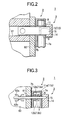
- the contact piece portions of the electrode pieces 12a, 12b or 13a, 13b of each of the pairs face each other across a corresponding one of the guide holes 11a and 11b. Moreover, as shown in Fig. 3, the contact piece portions of the electrode pieces of each of the pairs are bent so that the central parts thereof abut against each other. Therefore, the contact piece portions of the electrode pieces 12a, 12b or 13a, 13b of each of the pairs are made to extend along both sides of the corresponding one of the guide holes 11a, 11b, in other words, the plug fitting holes 9a and 9b, and to protrude therefrom.
- each of the electrode pieces may be constituted by, for instance, a metal ball and a spring for urging this metal ball so as to protrude into the plug fitting hole 9.
- the adapter body 2 may be constructed so that each of the electrode pieces 12 and 13 is attached to a predetermined portion, which is suitably formed in such a way as to be integral with the casing 7, and connected to the terminal portion of the circuit board 8 by a lead wire.
- the plug member 3 comprises a plate-shaped base portion 14, the entirety of which is formed from an insulating synthetic resin, and a pair of plug pieces 15a and 15b insert-molded into this base portion 14.
- the plug member 3 has a connection convex 16 formed on the top part of the base portion 14 in such a manner as to be integral therewith, and the other end of the aforementioned connection chain 4 is connected to the connection convex 16. It is sufficient for the base portion 14 to maintain the distance between the opposed plug pieces 15a and 15b and to support base end portions thereof. Thus, the base portion 14 does not require high mechanical strength. Consequently, the base portion 14 is formed in such a way as to be relatively thin.
- the plug pieces 15a and 15b are orthogonal to the primary face of this base portion 14 and placed in such a way as to be parallel to and to face each other.
- the distance between the plug pieces 15a and 15b is set to be equal to that between the plug holes 61a and 61b of the power supply receptacle 60.
- the size of a section of each of the plug pieces 15a and 15b is nearly equal to the opening size of each of the plug holes 61a and 61b.
- the distance between the plug pieces 15a and 15b and the size of the section of each of the plug pieces 15a and 15b are nearly equal to the distance between the plug fitting pieces 9a and 9b and the size of the section of each of the plug pieces 15a and 15b.
- each of the plug pieces 15a and 15b has a length that is sufficiently longer than the thickness of the casing 7 of the adapter body 2.
- the plug pieces 15a and 15b are fitted into the plug fitting holes 9a and 9b of the adapter body 2, respectively.
- the plug pieces 15a and 15b are respectively fitted into the plug fitting holes 9a and 9b from either of the front and rear primary faces 7a and 7b of the casing 7.
- the plug member 3 is adapted so that, for example, when the plug pieces 15a and 15b are respectively fitted into the plug fitting holes 9a and 9b from one of the primary faces 7a, the end portions of the plug pieces 15a and 15b protrude from the other primary face 7b of the casing 7.
- the plug member 3 is constructed so that the plug pieces 15a and 15b fitted into the plug fitting holes 9a and 9b penetrate through the adapter body 2 during push-opening the pair of electrode pieces 12a and 12b and the pair of the electrode pieces 13a and 13b, as illustrated in Fig. 3.
- the plug piece 15a is electrically conducted to the electrode pieces 12a and 12b
- the plug piece 15b is electrically conducted to the electrode pieces 13a and 13b. Consequently, the plug member 3 is connected to the AC-DC conversion circuit provided on the circuit board 8 that is built in the adapter body 2.
- the base portion 14 is formed in such a way as to be thin, has a certain degree of elasticity so as to be deformable. Therefore, when the AC adapter 1 is unused, the plug pieces 15a and 15b are pulled out of the plug fitting holes 9a and 9b, and the plug member 3 is placed on one side portion of the casing 7 such that the side portion is entered into a space between the plug pieces 15a and 15b. This makes the AC adapter 1 portable. Since the adapter body 2 and the plug member 3 are provided as individual members, appropriate position at which the plug member 3 is placed can be selected.
- the AC adapter 1 is fitted into the plug holes 61a and 61b of the power supply receptacle 60.
- the plug pieces 15a and 15b are sandwiched by the electrode spring members 62a and 62b of the power supply receptacle 60 so that AC power is supplied from the power supply receptacle 60 through the electrode spring members 62a and 62b to the AC adapter 1.
- the AC power is supplied to the AC-DC conversion circuit through the plug pieces 15a and 15b so that an AC voltage is converted into a predetermined DC voltage.
- the AC adapter 1 outputs a DC current, which is obtained by the conversion, from the connection code 5, and supplied the outputted DC current to equipment connected thereto.
- FIG. 4 An AC adapter 20 according to a second embodiment of the invention is illustrated in Figs. 4 and 5.
- the AC adapter 20 employs the adapter body 2 of the aforementioned AC adapter 1.
- a plug member 21 of the AC adapter 20 has a basic configuration, which has a connecting base portion 22 formed from an insulating synthetic resin material and a pair of plug pieces 23a and 23b insert-molded into this connection base portion 22, and which is similar to that of the plug member 3.
- connection base portion 22 is shaped like a thin rectangle having a length that is slightly longer than the distance between the plug fitting holes 9a and 9b of the adapter body 2.
- the connection base portion 22 has flexibility in the direction of thickness thereof.
- Plug pieces 23a and 23b are integrally insert-molded into the connection base portion 22 at both sides in the longitudinal direction thereof. As indicated by solid lines in Fig. 5, when unused, in the plug member 21, the plug pieces 23a and 23b are aligned in a line through the connection base portion 22, so that the entire plug member 21 is presented like a single plate.
- the plug pieces 23a and 23b are formed so that the size of a section of each of the plug pieces 23a and 23b is nearly equal to the opening size of each of the plug holes 61a and 61b.
- each of the plug pieces 23a and 23b is formed so that the distance therebetween and the size of the section thereof are nearly equal to the distance between and the opening size of the plug fitting holes 9a and 9b of the adapter body 2, respectively.
- Each of the pieces 23a and 23b has a length that is sufficiently longer than the thickness of the casing 7 of the adapter body 2. The insulation between the plug pieces 23a and 23b is held by the connection base portion 22.
- the plug pieces 23a and 23b of the plug member 21 do not project therefrom, so that these plug pieces do not hinder the AC adapter 20 from being carried. Consequently, not only the downsizing of the AC adapter 20 is achieved, but also the portability thereof is enhanced.
- the plug member 21 is adapted so that when the AC adapter 20 is used, the connection base portion 22 is bent so as to be U-shaped, as indicated by chain lines in Fig. 5.
- the plug member 21 is in such a condition that the plug pieces 23a and 23b are caused to face each other, the plug pieces 23a, 23a are fitted into the plug fitting holes 9a, 9a of the adapter body 2, as indicated by an arrow in Fig. 4.
- the plug pieces 23a, 23a of the plug member 21 are respectively fitted into the plug fitting holes 9a, 9b from the one of the primary faces 7a of the casing 7 of the adapter body 2, the end portions thereof project from the other primary face 7b of the casing 7.
- each of the plug pieces 23a, 23b fitted into the plug fitting holes 9a, 9b is electrically conducted to a corresponding one of pairs of electrode pieces 12a, 12b and electrode pieces 13a, 13b, which are projected into the guide holes 11a and 11b of the circuit board 8.
- the plug member 21 is connected to the AC-DC conversion circuit provided on the circuit board 8 built in the adapter body 2.
- the plug pieces 23a, 23a of the plug member 21, which are projected and exposed from the other primary face 7b of the casing 7 of the adapter body 2, are fitted into the plug holes 61a, 61b of the power supply receptacle 60.
- the plug pieces 23a, 23b are sandwiched by the electrode spring members 62a, 62a of the power supply receptacle 60 so that AC power is supplied from the power supply receptacle 60 to the AC-DC conversion circuit of the adapter body 2 of the AC adapter 20 through the electrode spring members 62a, 62b and the plug pieces 23a, 23b.
- the AC power is converted so that an AC voltage is converted into a predetermined DC voltage.
- the AC adapter 20 outputs a DC current, which is obtained by the conversion, from the connection code 5, and supplied the outputted DC current to equipment connected thereto.
- the plug member 21 becomes a single plate member in a normal condition, as described above, when the AC adapter 20 is carried or unused, the plug member 21 can be handled by being attached on the thin adapter body 22.
- the aforementioned AC adapter 20 does not employ such a structure in which the plug member is connected to the adapter body by a connection chain, which prevents the plug member from being lost. Therefore, a structure for holding the unused plug member 21 may be formed in the casing 7 of the AC adapter 20, similarly as the adapter body 2 illustrated in, for instance, Fig. 6.
- a plug member holder 25 is formed over the entirety of one of the side faces 7e in the longitudinal direction of the casing 7.
- the plug member holder 25 comprises a base portion holding part 25a of the central portion thereof, and plug piece holding parts 25b, 25c formed at both sides of this base portion holding part 25a in such a way as to communicate with each other.
- the base portion holding part 25a is shaped like a groove having a size, which is sufficient for fitting the connection base portion 22 of the plug member 21 thereinto.
- Each of the plug piece holding parts 25b, 25c is formed such that one end thereof is opened to this base portion holding part 25a, and that the other end of each of the plug piece holding parts 25b, 25c is opened to a corresponding one of the top face 7c and the bottom face 7c of the casing 7.
- Each of the plug piece holding parts 25b, 25c is shaped like a groove having a size, which is sufficient for fitting a corresponding one of the plug pieces 23a, 23b of the plug member 21 thereinto.
- the plug member 21 is assembled to the adapter body 2 by fitting, when the AC adapter 20 is unused, the connection base portion 22 into the base portion holding part 25a and moreover, fitting the plug pieces 23a, 23b into the plug piece holding parts 25b and 25c, respectively.
- the plug member 21 is formed in such a way as to be integral with the adapter body 2 by causing the groove walls of the plug member holder 25 to hold the connection base portion 22 or the plug pieces 23a, 23b. Therefore, according to the AC adapter 20, the plug member 21 is held by the adapter body 2, so that this plug member 21 is restrained by from being lost, and that the handling of this adapter is facilitated still more.
- the configuration of the plug member holder 25 is not limited to the aforementioned configuration.
- An appropriate locking convex adapted to project into the groove so as to more reliably hold the plug member 21 may be formed in such a way as to be integral therewith.
- the plug member holder 25 may be formed in such a way as to extend over other side faces orthogonal to the side face 7e.
Landscapes
- Connector Housings Or Holding Contact Members (AREA)
- Details Of Connecting Devices For Male And Female Coupling (AREA)
- Rectifiers (AREA)
Abstract
In a power conversion adapter which is connected to an AC power
supply receptacle to convert AC power supplied therefrom to DC power, a
casing body has a first principal face, a second principal face which extend in
parallel with each other, and at least one pair of connection passages
extending from the first principal face to the second principal face.
Conductive members are disposed within the casing body so as to elastically
protrude into the respective connection passages while being electrically
connected to an AC/DC converter. At least one plug member each includes a
base portion, and a pair of plug pieces extended from the base portion so as to
have a length which is longer than a length of the connection passages. The
plug member is detachably combined with one of the first principal face and
the second principal face of the casing body such that the plug pieces are
inserted into the connection passages while being electrically connected with
the conductive members. A portion of each plug piece protruded from the
other one of the first principal face and the second principal face is inserted
into each plug fitting hole of the AC power supply receptacle.
Description
- The present invention relates to a power conversion adapter (hereunder referred to as an AC adapter) connected to an AC power supply and adapted to perform power conversion by a built-in alternating current-direct current (AC-DC) conversion circuit and to output DC power to equipment connected thereto.
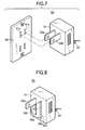
- AC adapters are used, for example, in the case of using a charger, which charges a rechargeable battery, and electronic equipment, which employs a DC power source as a power supply, by connecting the charger and the electronic equipment to a commercial power supply. Further, AC adapters convert DC to AC and supply AC to equipment connected thereto. As shown in Fig. 7, a first
related AC adapter 50 is constructed so that a circuit board (not shown), on which a power transformer (not shown) and components of a power supply circuit (not shown) are mounted, is built in acasing 51, that a pair ofplug pieces plug holes power supply receptacle 60 is provided on one of side faces of thecasing 51 in such a way as to protrude therefrom, and that aconnection code 53 to be connected to equipment (not shown) is drawn out of thecasing 51. - As portable telephones, various kinds of mobile equipment, and notebook personal computers come into wide use, it has been often that a user carries an AC adapter so as to charge a rechargeable battery, which is used as a power supply therefor, at a place away from home. As described above, a power transformer, which is relatively large in weight and size, is built in the first
related AC adapter 50. Therefore, the firstrelated AC adapter 50 has a drawback in that this related AC adapter is large in size and weight, and that it is difficult to carry this related AC adapter as a portable one. Moreover, theAC adapter 50 has another drawback in that theplug pieces - Meanwhile, the reduction in size and weight of the
AC adapter 50 can be achieved by, for example, employing thin film devices as various components of the AC-DC conversion circuit. However, as described above, theplug pieces casing 51 and as to project therefrom, so that the thickness of theentire AC adapter 50 cannot be reduced. Therefore, regarding AC adapters, for instance, a secondrelated AC adapter 55, in which each of the base portions of theplug pieces related AC adapter 57, in which theplug pieces casing 51 as illustrated in Fig. 9, have been provided. - The second
related AC adapter 55 is constructed so that when unused, theplug pieces casing 51, as represented by arrows in Fig. 8. Conversely, when used, theplug pieces plug holes 61 of thepower supply receptacle 60 by being rotated and operated in such a manner as to be orthogonal to thecasing 51, as represented by solid lines in this figure. Thus, theAC adapter 55 can be carried by accommodating, when unused, theplug pieces casing 51 so that theplug pieces AC adapter 55. - On the other hand, the third
related AC adapter 57 is constructed so that when unused, theplug pieces casing 51, as represented by arrows in Fig. 9, and that when used, theplug pieces casing 51 and plugged intoplug holes 61 of thepower supply receptacle 60, as represented by solid lines in this figure. With such a configuration, theadapter 57 can be carried so that theplug pieces AC adapter 57. - However, the second
related AC adapter 55 has a drawback in that because a bearing mechanism for rotating and supporting theplug pieces plug pieces plug pieces - Further, the
AC adapter 55 has a drawback in that because the slits 56, in which theplug pieces casing 51, a dead space is produced in thecasing 51, so that it is difficult to considerably reduce the size thereof. Furthermore, theAC adapter 55 has another drawback in that because theplug pieces casing 51 increases. - On the other hand, the third
related AC adapter 57 requires a lock mechanism for holding the plug pieces in an accommodated state or in a drawn-out state. Thus, theAC adapter 57 has drawbacks in that the number of components thereof is large, and that the structure thereof is complex. Moreover, in theAC adapter 57, a supporting portion for theplug pieces AC adapter 57 has another drawback in that the size thereof becomes larger when a supporting mechanism having large mechanical strength is constructed to thereby securely support theplug pieces AC adapter 57 is constructed so that thecasing 51 has a width sufficient to accommodate theplug pieces AC adapter 57 has another drawback in that there is a restriction on reduction in the entire size of theAC adapter 57. - It is therefore an object of the invention to provide a power conversion adapter that has a simple structure and that is enabled to significantly enhance the portability thereof by reduction in the weight and size thereof.
- In order to achieve the above object, according to the present invention, there is provided A power conversion adapter which is connected to an AC power supply receptacle to convert AC power supplied therefrom to DC power, comprising:
- a casing body having a first principal face and a second principal face which extend in parallel with each other, the casing body formed with at least one pair of connection passages extending from the first principal face to the second principal face;
- an AC/DC converter, deposed within the casing body;
- conductive members, disposed within the casing body so as to elastically protrude into the respective connection passages while being electrically connected to the AC/DC converter; and
- at least one plug member, each including:
- a base portion; and
- a pair of plug pieces extended from the base portion so as to have a length which is longer than a length of the connection passages, wherein:
- the plug member is detachably combined with one of the first principal
face and the second principal face of the casing body such that the plug pieces
are inserted into the connection passages while being electrically connected
with the conductive members; and
a portion of each plug piece protruded from the other one of the first principal face and the second principal face is inserted into each plug fitting hole of the AC power supply receptacle. -
- In this configuration, the casing body and the plug member are provided as individual members so that the plug pieces of the plug member are fitted into the connection passages of the casing body only when the adapter is connected to the power supply receptacle. Consequently, the plug pieces do not protrude from the casing body when the adapter is not used. Thus, the adapter can be treated by reducing the entire size and thickness of the adapter. Moreover, since the plug pieces are not hindrances to carrying the adapter, the portability thereof is significantly enhanced. Furthermore, since there is no necessity for a mechanism for rotating and supporting the plug pieces or for sliding and supporting the plug pieces, the structure thereof can be simplified. Therefore, the size, weight, thickness and cost thereof can be totally reduced.
- Preferably, the casing body has side end faces defining a distance between the first principal face and the second principal face as a thickness of the casing body. The thickness is substantially identical with a distance between the pair of plug pieces.
- Here, it is preferable that the plug member is attached on one of the side end faces of the casing body so that one side end portion of the casing body enters into a space defined by the pair of plug pieces, when the plug member is not connected to the AC power supply receptacle.
- Preferably, the power conversion adapter further comprises a chain member which connects the casing body and the plug member.
- Preferably, the base portion is provided as an elastic flat plate member from which the plug pieces are extended in opposite directions. The base portion is flexed such that the plug pieces extend in parallel with each other when the plug pieces are inserted into the connection passages.
- Here, it is preferable that a holder is formed on the casing body to hold the plug member thereon when the plug member is not connected to the AC power supply receptacle.
- The above objects and advantages of the present invention will become more apparent by describing in detail preferred exemplary embodiments thereof with reference to the accompanying drawings, wherein:
- Fig. 1 is an exploded perspective view illustrating an AC adapter according to a first embodiment of the invention;
- Fig. 2 is an enlarged vertical section view illustrating a state in which the AC adapter is connected to a power supply receptacle;
- Fig. 3 is an enlarged horizontal section view illustrating a state in which the AC adapter is connected to the power supply receptacle;
- Fig. 4 is an exploded perspective view illustrating an AC adapter according to a second embodiment of the invention;
- Fig. 5 is a perspective view illustrating a plug member used in the AC adapter of the second embodiment;
- Fig. 6 is a perspective view illustrating a state in which the plug member is combined with an adapter body of the AC adapter of the second embodiment;
- Fig. 7 is a perspective view illustrating a first related AC adapter;
- Fig. 8 is a perspective view illustrating a second related AC adapter; and
- Fig. 9 is a perspective view illustrating a third related AC adapter.
-
- Hereinafter, preferred embodiments of the invention will be described in detail with reference to the accompanying drawings.
- As illustrated in Figs. 1 to 3, an
AC adapter 1 according to a first embodiment comprises anadapter body 2 and aplug member 3, which are provided as individual members. Theplug member 3 is connected to theadapter body 2 by aconnection chain 4 so that theplug member 3 is prevented from being lost. As shown in Fig. 1, in theAC adapter 1, aconnection code 5 is drawn out of theadapter body 2. DC power is obtained by performing power conversion on commercial power and supplied by connecting aplug 6 provided at an end of thisconnection code 5 to a charger for charging a rechargeable battery or to electronic equipment that requires a DC power supply. - The
adapter body 2 has acasing 7 that is obtained by assembling a pair of halves formed like rectangular shallow pans from an insulating synthetic resin material and that is presented like a thin housing as a whole. Acircuit board 8 provided with an AC-DC conversion circuit, the description of details of which is omitted, is provided, is built in thiscasing 7. In theadapter body 2, appropriate electronic components of an AC-DC conversion circuit are mounted on thecircuit board 8. Moreover, coil elements and various thin film devices of a power transformer are formed on thecircuit board 8 by utilizing thin film formation techniques. A pair of plugfitting holes adapter body 2 in such a way as to penetrate through the front and rear principal faces 7a and 7b of thecasing 7. A connection convex 10 for connecting an end portion of aconnection chain 4 to one side face (top face) 7c in the longitudinal direction of thecasing 7 is provided on theadapter body 2 in such a manner as to be integral therewith and to protrude therefrom. - Incidentally, a drawing hole is formed in the other side face (bottom face) in the longitudinal direction of the
casing 7 of theadapter body 2. Theaforementioned connection code 5 is drawn therefrom by inserting a bush into this drawing hole so as to prevent the slip-off thereof and as to protect thecord 5. Theconnection code 5 is connected to an output terminal portion, which is formed on thecircuit board 8, at an end portion thereof drawn in to thecasing 7. Theconnection code 5 may be connected to theadapter body 2 by, for example, connecting a coaxial plug to an end thereof and inserting the coaxial plug into a jack attached to thecasing 7. - The plug
fitting holes casing 7 so that the distance therebetween and the opening size thereof are equal to the distance between the plug holes 61a and 61b and to the opening size of each of theholes holes circuit board 8 built in thecasing 7 in such a way as to penetrate therethrough, communicate with each other. Each of the guide holes 11a and 11b is formed in thecasing 8 so that the distance therebetween and the opening size thereof are equal to the distance between the plugfitting holes holes - A pair of
electrode pieces circuit board 8 in such a way as to be placed across theguide hole 11a, while a pair ofelectrode pieces circuit board 8 in such a way as to be placed across theguide hole 11b. Each of the pairs of theelectrode pieces electrode pieces circuit board 8 along an opening edge of a corresponding one of the guide holes 11a and 11b, and a contact piece portion that is formed in parallel with the guide holes 11a and 11b in such a way as to rise from this base portion. - The contact piece portions of the
electrode pieces electrode pieces guide holes fitting holes - Incidentally, each of the electrode pieces may be constituted by, for instance, a metal ball and a spring for urging this metal ball so as to protrude into the plug
fitting hole 9. Further, theadapter body 2 may be constructed so that each of theelectrode pieces casing 7, and connected to the terminal portion of thecircuit board 8 by a lead wire. - The
plug member 3 comprises a plate-shapedbase portion 14, the entirety of which is formed from an insulating synthetic resin, and a pair ofplug pieces 15a and 15b insert-molded into thisbase portion 14. Theplug member 3 has a connection convex 16 formed on the top part of thebase portion 14 in such a manner as to be integral therewith, and the other end of theaforementioned connection chain 4 is connected to the connection convex 16. It is sufficient for thebase portion 14 to maintain the distance between theopposed plug pieces 15a and 15b and to support base end portions thereof. Thus, thebase portion 14 does not require high mechanical strength. Consequently, thebase portion 14 is formed in such a way as to be relatively thin. - The
plug pieces 15a and 15b are orthogonal to the primary face of thisbase portion 14 and placed in such a way as to be parallel to and to face each other. The distance between theplug pieces 15a and 15b is set to be equal to that between the plug holes 61a and 61b of thepower supply receptacle 60. The size of a section of each of theplug pieces 15a and 15b is nearly equal to the opening size of each of the plug holes 61a and 61b. In other words, the distance between theplug pieces 15a and 15b and the size of the section of each of theplug pieces 15a and 15b are nearly equal to the distance between the plugfitting pieces plug pieces 15a and 15b. Moreover, each of theplug pieces 15a and 15b has a length that is sufficiently longer than the thickness of thecasing 7 of theadapter body 2. - In the
plug member 3 constructed as described above, theplug pieces 15a and 15b are fitted into the plugfitting holes adapter body 2, respectively. In theplug member 3, theplug pieces 15a and 15b are respectively fitted into the plugfitting holes casing 7. Theplug member 3 is adapted so that, for example, when theplug pieces 15a and 15b are respectively fitted into the plugfitting holes primary faces 7a, the end portions of theplug pieces 15a and 15b protrude from the otherprimary face 7b of thecasing 7. - The
plug member 3 is constructed so that theplug pieces 15a and 15b fitted into the plugfitting holes adapter body 2 during push-opening the pair ofelectrode pieces electrode pieces plug member 3, the plug piece 15a is electrically conducted to theelectrode pieces plug piece 15b is electrically conducted to theelectrode pieces plug member 3 is connected to the AC-DC conversion circuit provided on thecircuit board 8 that is built in theadapter body 2. - As described the above, the
base portion 14 is formed in such a way as to be thin, has a certain degree of elasticity so as to be deformable. Therefore, when theAC adapter 1 is unused, theplug pieces 15a and 15b are pulled out of the plugfitting holes plug member 3 is placed on one side portion of thecasing 7 such that the side portion is entered into a space between theplug pieces 15a and 15b. This makes theAC adapter 1 portable. Since theadapter body 2 and theplug member 3 are provided as individual members, appropriate position at which theplug member 3 is placed can be selected. - After combining the
adapter body 2 and theplug member 3 such that the end portions of theplug pieces 15a and 15b are protruded and exposed from theprimary face 7b of thecasing 7 as described the above, theAC adapter 1 is fitted into the plug holes 61a and 61b of thepower supply receptacle 60. Theplug pieces 15a and 15b are sandwiched by theelectrode spring members power supply receptacle 60 so that AC power is supplied from thepower supply receptacle 60 through theelectrode spring members AC adapter 1. - In the
AC adapter 1, the AC power is supplied to the AC-DC conversion circuit through theplug pieces 15a and 15b so that an AC voltage is converted into a predetermined DC voltage. TheAC adapter 1 outputs a DC current, which is obtained by the conversion, from theconnection code 5, and supplied the outputted DC current to equipment connected thereto. - An
AC adapter 20 according to a second embodiment of the invention is illustrated in Figs. 4 and 5. In this embodiment, there is provided a configuration having aplug member 21 that enables further reduction in the size of the AC adapter. TheAC adapter 20 employs theadapter body 2 of theaforementioned AC adapter 1. Thus, the detail description of the adapter body of theAC adapter 20 is omitted herein. Aplug member 21 of theAC adapter 20 has a basic configuration, which has a connectingbase portion 22 formed from an insulating synthetic resin material and a pair ofplug pieces connection base portion 22, and which is similar to that of theplug member 3. - In the
plug member 21, theconnection base portion 22 is shaped like a thin rectangle having a length that is slightly longer than the distance between the plugfitting holes adapter body 2. Theconnection base portion 22 has flexibility in the direction of thickness thereof.Plug pieces connection base portion 22 at both sides in the longitudinal direction thereof. As indicated by solid lines in Fig. 5, when unused, in theplug member 21, theplug pieces connection base portion 22, so that theentire plug member 21 is presented like a single plate. - The
plug pieces plug pieces plug pieces fitting holes adapter body 2, respectively. Each of thepieces casing 7 of theadapter body 2. The insulation between theplug pieces connection base portion 22. Therefore, in theAC adapter 20, theplug pieces plug member 21 do not project therefrom, so that these plug pieces do not hinder theAC adapter 20 from being carried. Consequently, not only the downsizing of theAC adapter 20 is achieved, but also the portability thereof is enhanced. - The
plug member 21 is adapted so that when theAC adapter 20 is used, theconnection base portion 22 is bent so as to be U-shaped, as indicated by chain lines in Fig. 5. When theplug member 21 is in such a condition that theplug pieces plug pieces fitting holes adapter body 2, as indicated by an arrow in Fig. 4. When theplug pieces plug member 21 are respectively fitted into the plugfitting holes casing 7 of theadapter body 2, the end portions thereof project from the otherprimary face 7b of thecasing 7. - In the
plug member 21, each of theplug pieces fitting holes electrode pieces electrode pieces circuit board 8. Thus, theplug member 21 is connected to the AC-DC conversion circuit provided on thecircuit board 8 built in theadapter body 2. - After the
plug member 21 is combined with theadapter body 2 as described above, the end portions of theplug pieces plug member 21, which are projected and exposed from the otherprimary face 7b of thecasing 7 of theadapter body 2, are fitted into theplug holes power supply receptacle 60. In theAC adapter 20, theplug pieces electrode spring members power supply receptacle 60 so that AC power is supplied from thepower supply receptacle 60 to the AC-DC conversion circuit of theadapter body 2 of theAC adapter 20 through theelectrode spring members plug pieces - In the AC-DC conversion circuit of the
AC adapter 20, the AC power is converted so that an AC voltage is converted into a predetermined DC voltage. TheAC adapter 20 outputs a DC current, which is obtained by the conversion, from theconnection code 5, and supplied the outputted DC current to equipment connected thereto. - Since the
plug member 21 becomes a single plate member in a normal condition, as described above, when theAC adapter 20 is carried or unused, theplug member 21 can be handled by being attached on thethin adapter body 22. - Namely, the
aforementioned AC adapter 20 does not employ such a structure in which the plug member is connected to the adapter body by a connection chain, which prevents the plug member from being lost. Therefore, a structure for holding theunused plug member 21 may be formed in thecasing 7 of theAC adapter 20, similarly as theadapter body 2 illustrated in, for instance, Fig. 6. - That is, in the
adapter body 2, aplug member holder 25 is formed over the entirety of one of the side faces 7e in the longitudinal direction of thecasing 7. Theplug member holder 25 comprises a baseportion holding part 25a of the central portion thereof, and plugpiece holding parts portion holding part 25a in such a way as to communicate with each other. The baseportion holding part 25a is shaped like a groove having a size, which is sufficient for fitting theconnection base portion 22 of theplug member 21 thereinto. Each of the plugpiece holding parts portion holding part 25a, and that the other end of each of the plugpiece holding parts top face 7c and thebottom face 7c of thecasing 7. Each of the plugpiece holding parts plug pieces plug member 21 thereinto. - As illustrated in Fig. 6, the
plug member 21 is assembled to theadapter body 2 by fitting, when theAC adapter 20 is unused, theconnection base portion 22 into the baseportion holding part 25a and moreover, fitting theplug pieces piece holding parts plug member 21 is formed in such a way as to be integral with theadapter body 2 by causing the groove walls of theplug member holder 25 to hold theconnection base portion 22 or theplug pieces AC adapter 20, theplug member 21 is held by theadapter body 2, so that thisplug member 21 is restrained by from being lost, and that the handling of this adapter is facilitated still more. - Incidentally, regarding the
adapter body 2, the configuration of theplug member holder 25 is not limited to the aforementioned configuration. An appropriate locking convex adapted to project into the groove so as to more reliably hold theplug member 21 may be formed in such a way as to be integral therewith. Further, regarding theadapter body 2, when the length of theplug member 21 is longer than that of theside face 7e of thecasing 7, theplug member holder 25 may be formed in such a way as to extend over other side faces orthogonal to theside face 7e. - Although the present invention has been shown and described with reference to specific preferred embodiments, various changes and modifications will be apparent to those skilled in the art from the teachings herein. Such changes and modifications as are obvious are deemed to come within the spirit, scope and contemplation of the invention as defined in the appended claims.
Claims (6)
- A power conversion adapter which is connected to an AC power supply receptacle to convert AC power supplied therefrom to DC power, comprising:a casing body having a first principal face and a second principal face which extend in parallel with each other, the casing body formed with at least one pair of connection passages extending from the first principal face to the second principal face;an AC/DC converter, deposed within the casing body;conductive members, disposed within the casing body so as to elastically protrude into the respective connection passages while being electrically connected to the AC/DC converter; andat least one plug member, each including:a base portion; anda pair of plug pieces extended from the base portion so as to have a length which is longer than a length of the connection passages, wherein:the plug member is detachably combined with one of the first principal face and the second principal face of the casing body such that the plug pieces are inserted into the connection passages while being electrically connected with the conductive members; anda portion of each plug piece protruded from the other one of the first principal face and the second principal face is inserted into each plug fitting hole of the AC power supply receptacle.
- The power conversion adapter as set forth in claim 1, wherein:the casing body has side end faces defining a distance between the first principal face and the second principal face as a thickness of the casing body; andthe thickness is substantially identical with a distance between the pair of plug pieces.
- The power conversion adapter as set forth in claim 2, wherein the plug member is attached on one of the side end faces of the casing body so that one side end portion of the casing body enters into a space defined by the pair of plug pieces, when the plug member is not connected to the AC power supply receptacle.
- The power conversion adapter as set forth in claim 1, further comprising a chain member which connects the casing body and the plug member.
- The power conversion adapter as set forth in claim 1, wherein:the base portion is provided as an elastic flat plate member from which the plug pieces are extended in opposite directions; andthe base portion is flexed such that the plug pieces extend in parallel with each other when the plug pieces are inserted into the connection passages.
- The power conversion adapter as set forth in claim 5, wherein a holder is formed on the casing body to hold the plug member thereon when the plug member is not connected to the AC power supply receptacle.
Applications Claiming Priority (2)
| Application Number | Priority Date | Filing Date | Title |
|---|---|---|---|
| JP2001053059A JP4517265B2 (en) | 2001-02-27 | 2001-02-27 | Power conversion adapter device |
| JP2001053059 | 2001-02-27 |
Publications (1)
| Publication Number | Publication Date |
|---|---|
| EP1235312A1 true EP1235312A1 (en) | 2002-08-28 |
Family
ID=18913585
Family Applications (1)
| Application Number | Title | Priority Date | Filing Date |
|---|---|---|---|
| EP02004554A Withdrawn EP1235312A1 (en) | 2001-02-27 | 2002-02-27 | Power conversion adapter |
Country Status (3)
| Country | Link |
|---|---|
| US (1) | US20020118561A1 (en) |
| EP (1) | EP1235312A1 (en) |
| JP (1) | JP4517265B2 (en) |
Families Citing this family (17)
| Publication number | Priority date | Publication date | Assignee | Title |
|---|---|---|---|---|
| IL157787A (en) * | 2003-09-07 | 2010-12-30 | Mosaid Technologies Inc | Modular outlet for data communications network |
| IL160417A (en) | 2004-02-16 | 2011-04-28 | Mosaid Technologies Inc | Outlet add-on module |
| US20090059636A1 (en) * | 2007-08-29 | 2009-03-05 | Cyber Power System Inc. | Power adapter having an electricity storing capability |
| US7896702B2 (en) * | 2008-06-06 | 2011-03-01 | Apple Inc. | Compact power adapter |
| US8021198B2 (en) | 2008-06-06 | 2011-09-20 | Apple Inc. | Low-profile power adapter |
| US8021183B2 (en) | 2008-10-31 | 2011-09-20 | Apple Inc. | Cold headed electric plug arm |
| US8934261B2 (en) * | 2008-12-23 | 2015-01-13 | Apple Inc. | Compact device housing and assembly techniques therefor |
| USD610993S1 (en) * | 2009-06-23 | 2010-03-02 | Research In Motion Limited | Plug |
| USD610992S1 (en) * | 2009-06-23 | 2010-03-02 | Research In Motion Limited | Plug |
| USD617275S1 (en) * | 2009-06-25 | 2010-06-08 | Research In Motion Limited | Plug |
| TWI392174B (en) * | 2009-10-09 | 2013-04-01 | Outlet device and the method of connection | |
| CN105186244B (en) * | 2009-10-27 | 2018-04-24 | 胜德国际研发股份有限公司 | Socket device and method for connecting socket device |
| CN102610974B (en) * | 2012-03-19 | 2014-10-08 | 李林山 | Rubber elastic socket of parallel-line-shaped jacks and matched plug |
| US20140140010A1 (en) * | 2012-11-16 | 2014-05-22 | Lien Chang Electronic Enterprise Co., Ltd. | Current converting device |
| US9853384B2 (en) | 2014-02-27 | 2017-12-26 | Ran Azoulay | Socket apparatus |
| IL231214A0 (en) * | 2014-02-27 | 2014-08-31 | Ran Azoulay | Socket apparatus |
| US9548578B2 (en) * | 2014-02-27 | 2017-01-17 | Ran Azoulay | Socket apparatus |
Citations (3)
| Publication number | Priority date | Publication date | Assignee | Title |
|---|---|---|---|---|
| GB2326540A (en) * | 1997-05-09 | 1998-12-23 | Formosa Electronic Ind Inc | AC/DC power supply |
| US5967807A (en) * | 1997-08-20 | 1999-10-19 | Formosa Electronic Industries Inc. | AC/DC electric adapter with the large and small plugs |
| US5973948A (en) * | 1996-06-19 | 1999-10-26 | Advanced Mobile Solutions, Inc. | Universal linear power supply |
Family Cites Families (5)
| Publication number | Priority date | Publication date | Assignee | Title |
|---|---|---|---|---|
| JPS5338140Y2 (en) * | 1973-02-21 | 1978-09-14 | ||
| JPH0340622U (en) * | 1989-08-29 | 1991-04-18 | ||
| JPH07337016A (en) * | 1994-05-31 | 1995-12-22 | Mitsumi Electric Co Ltd | Power adapter |
| JPH08111263A (en) * | 1994-10-11 | 1996-04-30 | 英明 ▲かせ▼谷 | Adapter for grounding |
| JP3139452B2 (en) * | 1998-04-10 | 2001-02-26 | 日本電気株式会社 | Piezoelectric transformer and method of manufacturing the same |
-
2001
- 2001-02-27 JP JP2001053059A patent/JP4517265B2/en not_active Expired - Fee Related
-
2002
- 2002-02-26 US US10/082,200 patent/US20020118561A1/en not_active Abandoned
- 2002-02-27 EP EP02004554A patent/EP1235312A1/en not_active Withdrawn
Patent Citations (3)
| Publication number | Priority date | Publication date | Assignee | Title |
|---|---|---|---|---|
| US5973948A (en) * | 1996-06-19 | 1999-10-26 | Advanced Mobile Solutions, Inc. | Universal linear power supply |
| GB2326540A (en) * | 1997-05-09 | 1998-12-23 | Formosa Electronic Ind Inc | AC/DC power supply |
| US5967807A (en) * | 1997-08-20 | 1999-10-19 | Formosa Electronic Industries Inc. | AC/DC electric adapter with the large and small plugs |
Also Published As
| Publication number | Publication date |
|---|---|
| US20020118561A1 (en) | 2002-08-29 |
| JP2002260768A (en) | 2002-09-13 |
| JP4517265B2 (en) | 2010-08-04 |
Similar Documents
| Publication | Publication Date | Title |
|---|---|---|
| US20020118561A1 (en) | Power conversion adapter | |
| US7439709B2 (en) | Charger unit for an electronic device including a system for protective storage of an adapter plug | |
| TW417325B (en) | Battery connection apparatus | |
| US8944845B2 (en) | Power plug, electrical plug assembly and electrical charger assembly | |
| US7746029B2 (en) | Battery charger with USB connector and cable storage recess | |
| US20080076279A1 (en) | Foldable electrical connector and power supply apparatus having same | |
| US10355424B2 (en) | Electronic device holder | |
| US10061351B2 (en) | Portable user device | |
| JP3902074B2 (en) | Movable plug head | |
| JPH0636749A (en) | Battery-incorporated electronic equipment device | |
| KR101248698B1 (en) | Intertia enhanced latching system and electronic device having a latching system | |
| US6807067B2 (en) | Battery-Locking mechanism | |
| US20050170676A1 (en) | Battery charger | |
| JP2003051875A (en) | Charger for wireless telephone | |
| US7411795B2 (en) | Desktop holder for portable terminal | |
| JP2002247775A (en) | Stand for charging | |
| JP4133900B2 (en) | Portable device charging stand and portable device charging system | |
| JP3331324B2 (en) | AC adapter for mobile phone charging | |
| EP1158645A1 (en) | A compact charger for an electronic device | |
| KR20180010081A (en) | Multipurpose cable, cable holder, and portable assisting devive using the same | |
| CN221632906U (en) | A mobile power source | |
| CN223023645U (en) | Pin assembly and electronic equipment | |
| EP1162703A2 (en) | Pivotal power supply plug device | |
| KR100598087B1 (en) | Battery Case Device for Electronic Devices | |
| GB2411777A (en) | Combination plug for mobile phone charger |
Legal Events
| Date | Code | Title | Description |
|---|---|---|---|
| PUAI | Public reference made under article 153(3) epc to a published international application that has entered the european phase |
Free format text: ORIGINAL CODE: 0009012 |
|
| AK | Designated contracting states |
Kind code of ref document: A1 Designated state(s): AT BE CH CY DE DK ES FI FR GB GR IE IT LI LU MC NL PT SE TR |
|
| AX | Request for extension of the european patent |
Free format text: AL;LT;LV;MK;RO;SI |
|
| AKX | Designation fees paid | ||
| REG | Reference to a national code |
Ref country code: DE Ref legal event code: 8566 |
|
| STAA | Information on the status of an ep patent application or granted ep patent |
Free format text: STATUS: THE APPLICATION IS DEEMED TO BE WITHDRAWN |
|
| 18D | Application deemed to be withdrawn |
Effective date: 20030301 |