EP1235300A2 - GPS antenna unit for two-wheeled motor vehicle - Google Patents
GPS antenna unit for two-wheeled motor vehicle Download PDFInfo
- Publication number
- EP1235300A2 EP1235300A2 EP02003933A EP02003933A EP1235300A2 EP 1235300 A2 EP1235300 A2 EP 1235300A2 EP 02003933 A EP02003933 A EP 02003933A EP 02003933 A EP02003933 A EP 02003933A EP 1235300 A2 EP1235300 A2 EP 1235300A2
- Authority
- EP
- European Patent Office
- Prior art keywords
- motor vehicle
- wheeled motor
- gps antenna
- unit
- antenna
- Prior art date
- Legal status (The legal status is an assumption and is not a legal conclusion. Google has not performed a legal analysis and makes no representation as to the accuracy of the status listed.)
- Granted
Links
Images


Classifications
-
- H—ELECTRICITY
- H01—ELECTRIC ELEMENTS
- H01Q—ANTENNAS, i.e. RADIO AERIALS
- H01Q11/00—Electrically-long antennas having dimensions more than twice the shortest operating wavelength and consisting of conductive active radiating elements
- H01Q11/02—Non-resonant antennas, e.g. travelling-wave antenna
- H01Q11/08—Helical antennas
-
- B—PERFORMING OPERATIONS; TRANSPORTING
- B60—VEHICLES IN GENERAL
- B60C—VEHICLE TYRES; TYRE INFLATION; TYRE CHANGING; CONNECTING VALVES TO INFLATABLE ELASTIC BODIES IN GENERAL; DEVICES OR ARRANGEMENTS RELATED TO TYRES
- B60C23/00—Devices for measuring, signalling, controlling, or distributing tyre pressure or temperature, specially adapted for mounting on vehicles; Arrangement of tyre inflating devices on vehicles, e.g. of pumps or of tanks; Tyre cooling arrangements
- B60C23/005—Devices specially adapted for special wheel arrangements
- B60C23/006—Devices specially adapted for special wheel arrangements having two wheels only
-
- B—PERFORMING OPERATIONS; TRANSPORTING
- B60—VEHICLES IN GENERAL
- B60C—VEHICLE TYRES; TYRE INFLATION; TYRE CHANGING; CONNECTING VALVES TO INFLATABLE ELASTIC BODIES IN GENERAL; DEVICES OR ARRANGEMENTS RELATED TO TYRES
- B60C23/00—Devices for measuring, signalling, controlling, or distributing tyre pressure or temperature, specially adapted for mounting on vehicles; Arrangement of tyre inflating devices on vehicles, e.g. of pumps or of tanks; Tyre cooling arrangements
- B60C23/02—Signalling devices actuated by tyre pressure
- B60C23/04—Signalling devices actuated by tyre pressure mounted on the wheel or tyre
- B60C23/0408—Signalling devices actuated by tyre pressure mounted on the wheel or tyre transmitting the signals by non-mechanical means from the wheel or tyre to a vehicle body mounted receiver
- B60C23/0422—Signalling devices actuated by tyre pressure mounted on the wheel or tyre transmitting the signals by non-mechanical means from the wheel or tyre to a vehicle body mounted receiver characterised by the type of signal transmission means
- B60C23/0433—Radio signals
- B60C23/0435—Vehicle body mounted circuits, e.g. transceiver or antenna fixed to central console, door, roof, mirror or fender
- B60C23/0444—Antenna structures, control or arrangements thereof, e.g. for directional antennas, diversity antenna, antenna multiplexing or antennas integrated in fenders
-
- G—PHYSICS
- G01—MEASURING; TESTING
- G01S—RADIO DIRECTION-FINDING; RADIO NAVIGATION; DETERMINING DISTANCE OR VELOCITY BY USE OF RADIO WAVES; LOCATING OR PRESENCE-DETECTING BY USE OF THE REFLECTION OR RERADIATION OF RADIO WAVES; ANALOGOUS ARRANGEMENTS USING OTHER WAVES
- G01S19/00—Satellite radio beacon positioning systems; Determining position, velocity or attitude using signals transmitted by such systems
- G01S19/01—Satellite radio beacon positioning systems transmitting time-stamped messages, e.g. GPS [Global Positioning System], GLONASS [Global Orbiting Navigation Satellite System] or GALILEO
- G01S19/13—Receivers
- G01S19/14—Receivers specially adapted for specific applications
-
- H—ELECTRICITY
- H01—ELECTRIC ELEMENTS
- H01Q—ANTENNAS, i.e. RADIO AERIALS
- H01Q1/00—Details of, or arrangements associated with, antennas
- H01Q1/27—Adaptation for use in or on movable bodies
- H01Q1/32—Adaptation for use in or on road or rail vehicles
- H01Q1/325—Adaptation for use in or on road or rail vehicles characterised by the location of the antenna on the vehicle
- H01Q1/3266—Adaptation for use in or on road or rail vehicles characterised by the location of the antenna on the vehicle using the mirror of the vehicle
Definitions
- the present invention relates to a GPS antenna for a two-wheeled motor vehicle and more particularly to a GPS antenna for a two-wheeled motor vehicle which can be mounted without impairing the appearance of the two-wheeled motor vehicle.
- a GPS antenna for a four-wheeled motor vehicle such as a private vehicle disclosed in Japanese Patent Laid-open No. Hei 4-326202
- a plane antenna so-called a patch antenna which is square in shape, 20 to 60 mm long by 20 to 60 mm wide, or which is in the shape of a disc having a diameter of 20 to 60 mm.
- a large number of antenna elements can be integrated and therefore there can be attained an extremely high directivity in the vertical direction.
- the adoption of a diversity configuration can afford a good condition for reception.
- the abobe-described plane antenna is high in its directivity in the vertical direction and is low in its sensitivity in the horizontal direction, so is difficult to be influenced by a multi-path and an ionospheric delay.
- a plane antenna for a GPS of a moving body which undergoes a great change in posture during travel, such as a two-wheeled motor vehicle, then in a tilted state of the vehicle body, a strong directivity of the plane antenna acts on a radio wave emitted from a satellite with a low elevation angle, with consequent deterioration of the accuracy.
- a GPS antenna unit for a two-wheeled motor vehicle mounted to the two-wheeled motor vehicle to receive a radio wave from a GPS satellite, including a helical antenna extending to the exterior from a unit case and a controller accommodated within the unit case to process the radio wave received by the helical antenna.
- the GPS antenna can be mounted to even to a two-wheeled motor vehicle having few planar portions which face the zenith, without impairing the appearance and aerodynamic characteristics of the vehicle.
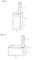
- FIG. 1 is a perspective view of a GPS antenna unit 1 according to an embodiment of the present invention.
- the GPS antenna unit 1 includes a unit case 11 of a cubic shape, a helical antenna 12 extending to the exterior from the unit case 11, and a control circuit board 13 accommodated within the unit case 11, the control circuit board 13 amplifying a radio wave received by the helical antenna 12 and converting it into a predetermined format.
- the unit case 11 is long in an axial direction of the helical antenna 12. However, as shown in FIG. 2, it may be long in a direction perpendicular to the axis of the helical antenna 12.
- the GPS antenna is formed as the helical antenna 12 and the projection area of the antenna itself can be made small in a plane perpendicular to the axis of the helical antenna, so when the GPS antenna unit 1 is to be installed in a two-wheeled motor vehicle, the helical antenna 12 can be installed so as to face the zenith by utilizing a limited space. Consequently, it becomes possible for the GPS antenna unit to be mounted even to a two-wheeled motor vehicle without impairing the appearance and aerodynamic characteristics of the vehicle.
- an axis ratio (the ratio of directivity in the axial direction to directivity in a direction perpendicular to the axis) can be adjusted as desired by adjusting the number of turns of a coil, so if the axis ratio is adjusted taking posture changes peculiar to the two-wheeled motor vehicle into account, it becomes possible to obtain an optimum directivity irrespective of posture changes.
- FIG. 3 shows an example in which the GPS antenna unit 1 is attached to a side mirror 20, in which 3(a) is a sectional view and 3(b) is a plan view of a mirror surface side.
- the unit case 11 is accommodated in a dead space present between a mirror 22 and the cover 21 in the interior of the side mirror 20 and the helical antenna 12 can be exposed to the exterior by utilizing a limited space present above the upper surface of the side mirror.
- the GPS antenna can be installed without impairing the appearance and aerodynamic characteristics of the vehicle.
- FIG. 5 is a side view of a two-wheeled motor vehicle for explaining an another embodiment of the present invention.
- the GPS antenna unit 1 can be mounted inside a side face of a front fender 30, inside a side face of a front cowl 40, inside a side face of an under-cowl 50, inside a side face of a rear fender 60, or inside a side face of a seat cowl 70.
- FIG. 6 shows concretely an example of mounting the GPS antenna unit 1 to the front fender 30, in which the same reference numerals as above represent the same or equivalent portions. Also to the other fender or cowls the GPS antenna unit 1 can be mounted in the same manner as above, so associated explanations will here be omitted.
- the GPS antenna unit 1 is mounted in a gap between a front tire FW and the front fender 30, i.e., inside a side face of the front fender 30.
- the helical antenna 12, as shown also in FIG. 6(a), is exposed to the exterior from an aperture 24 formed in a inclined surface of the front fender 30.
- the unit case 11 can be fixed inside a side face of a fender or a cowl and the helical antenna 12 can be exposed to the exterior by utilizing a inclined surface of the fender or the cowl, so that the GPS antenna unit can be mounted to the two-wheeled motor vehicle without impairing the appearance and aerodynamic characteristics of the vehicle.
- the GPS antenna unit 1 is built into a side mirror or mounted inside a fender or a cowl.
- the helical antenna 12 it is possible to diminish the projection area of the antenna 12 itself, so that the GPS antenna unit 1 can also be installed within a meter panel, a headlight, or a winker.
- GPS antenna unit of this embodiment can be retrofitted to an existing vehicle, but may be installed beforehand in such a component as a side mirror, a fender, or a cowl.
- the GPS antenna unit 1 may be installed within the side mirror in the process of assembly of the side mirror itself, affording a GPS antenna unit-incorporated side mirror.
- the GPS antenna unit 1 may be mounted to the front fender 30 during assembly of the front fender to afford a front fender with GPS antenna unit.
- the associated component when mounted to a two-wheeled motor vehicle at its own regular posture, holds the unit case 11 at a predetermined posture so that the helical antenna 12 faces the zenith.
- a GPS antenna unit for a two-wheeled motor vehicle capable of being mounted to the vehicle without impairing the appearance of the vehicle is to be provided.
- a GPS antenna unit for a two-wheeled motor vehicle, mounted to the two-wheeled motor vehicle to receive a radio wave from a GPS satellite includes a helical antenna 12 extending to the exterior from a unit case 11 and a controller 13 accommodated within the unit case 11 to process the radio wave received by the helical antenna 12. Since the projection area of the helical antenna is small, the GPS antenna can be mounted even to a two-wheeled motor vehicle having few planar portions facing the zenith, without impairing the appearance and aerodynamic characteristics of the vehicle.
Landscapes
- Engineering & Computer Science (AREA)
- Remote Sensing (AREA)
- Mechanical Engineering (AREA)
- Radar, Positioning & Navigation (AREA)
- Computer Networks & Wireless Communication (AREA)
- Physics & Mathematics (AREA)
- General Physics & Mathematics (AREA)
- Support Of Aerials (AREA)
- Details Of Aerials (AREA)
- Fittings On The Vehicle Exterior For Carrying Loads, And Devices For Holding Or Mounting Articles (AREA)
Abstract
Description
A GPS antenna unit for a two-wheeled motor vehicle, mounted to the two-wheeled motor vehicle to receive a radio wave from a GPS satellite includes a
Claims (7)
- A GPS antenna unit for a two-wheeled motor vehicle, mounted to the two-wheeled motor vehicle to receive a radio wave from a GPS satellite, comprising:a helical antenna (12) extending to the exterior from a unit case (11); anda controller (13) accommodated within said unit case (11) to process the radio wave received by said helical antenna (12).
- A GPS antenna unit for a two-wheeled motor vehicle, mounted to the two-wheeled motor vehicle to receive a radio wave from a GPS satellite, comprising:wherein said component (20; 30; 40; 50; 60; 70) for the two-wheeled motor vehicle holds said unit case (11) in a predetermined posture so that said helical antenna (12) faces the zenith when said component (20; 30; 40; 50; 60; 70) is attached to the two-wheeled motor vehicle in a regular posture thereof.a helical antenna (12) extending to the exterior from a unit case (11);a controller (13) accommodated within said unit case (11) to process the radio wave received by said helical antenna (12); anda component (20; 30; 40; 50; 60; 70) for the two-wheeled motor vehicle, said component (20; 30; 40; 50; 60; 70) holding said unit case (11),
- A GPS antenna unit for a two-wheeled motor vehicle according to claim 2, wherein said component (20) for the two-wheeled motor vehicle is a side mirror (20) and said unit case (11) is incorporated in said side mirror (20).
- A GPS antenna unit for a two-wheeled motor vehicle according to claim 2, wherein said component (40; 50; 70) for the two-wheeled motor vehicle is a cowl (40; 50; 70) and said unit case (11) is mounted inside said cowl (40; 50; 70).
- A GPS antenna unit for a two-wheeled motor vehicle according to claim 2, wherein said component (30; 60) for the two-wheeled motor vehicle is a fender (30; 60) and said unit case (11) is mounted inside said fender (30; 60).
- A GPS antenna unit for a two-wheeled motor vehicle according to claim 2, wherein said component for the two-wheeled motor vehicle is a headlight and said unit case (11) is incorporated in said headlight.
- A GPS antenna unit for a two-wheeled motor vehicle according to claim 2, wherein said component for the two-wheeled motor vehicle is a meter panel and said unit case (11) is incorporated in said meter panel. gh/27162pep.honda.cls
Applications Claiming Priority (2)
| Application Number | Priority Date | Filing Date | Title |
|---|---|---|---|
| JP2001052324A JP2002261525A (en) | 2001-02-27 | 2001-02-27 | GPS antenna unit for motorcycles |
| JP2001052324 | 2001-02-27 |
Publications (3)
| Publication Number | Publication Date |
|---|---|
| EP1235300A2 true EP1235300A2 (en) | 2002-08-28 |
| EP1235300A3 EP1235300A3 (en) | 2003-11-26 |
| EP1235300B1 EP1235300B1 (en) | 2009-10-14 |
Family
ID=18912974
Family Applications (1)
| Application Number | Title | Priority Date | Filing Date |
|---|---|---|---|
| EP02003933A Expired - Lifetime EP1235300B1 (en) | 2001-02-27 | 2002-02-21 | GPS antenna unit for two-wheeled motor vehicle |
Country Status (6)
| Country | Link |
|---|---|
| US (1) | US6778143B2 (en) |
| EP (1) | EP1235300B1 (en) |
| JP (1) | JP2002261525A (en) |
| CN (1) | CN1207573C (en) |
| DE (1) | DE60233992D1 (en) |
| TW (1) | TW565701B (en) |
Families Citing this family (11)
| Publication number | Priority date | Publication date | Assignee | Title |
|---|---|---|---|---|
| JP4363559B2 (en) * | 2002-09-11 | 2009-11-11 | 本田技研工業株式会社 | A saddle-ride type vehicle with a navigation system |
| FR2866986B1 (en) * | 2004-02-27 | 2006-06-16 | Michelin Soc Tech | WHEEL PASSAGE COMPRISING AN ANTENNA |
| US10608348B2 (en) | 2012-03-31 | 2020-03-31 | SeeScan, Inc. | Dual antenna systems with variable polarization |
| US10490908B2 (en) | 2013-03-15 | 2019-11-26 | SeeScan, Inc. | Dual antenna systems with variable polarization |
| DE102013222951A1 (en) * | 2013-11-12 | 2015-05-13 | Bayerische Motoren Werke Aktiengesellschaft | Antenna assembly for a motor vehicle and motor vehicle with the antenna assembly |
| US10714816B2 (en) | 2016-06-10 | 2020-07-14 | Cnh Industrial America Llc | Antenna mounting arrangement for a work vehicle |
| US10153543B2 (en) | 2016-06-10 | 2018-12-11 | Cnh Industrial America Llc | Antenna mounting arrangement for an off-road vehicle |
| JP7084476B2 (en) * | 2018-05-23 | 2022-06-14 | 本田技研工業株式会社 | Saddle-type vehicle |
| JP6929468B2 (en) * | 2018-08-27 | 2021-09-01 | ヤマハ発動機株式会社 | Vehicle-to-vehicle communication antenna device and lean vehicle |
| CN112739612B (en) * | 2018-09-28 | 2022-06-14 | 本田技研工业株式会社 | Saddle-ride type vehicle |
| IT201800010894A1 (en) * | 2018-12-07 | 2020-06-07 | Piaggio & C Spa | RIDING SADDLE VEHICLE INCLUDING A SYSTEM FOR REDUCING THE RISK OF COLLISION |
Family Cites Families (21)
| Publication number | Priority date | Publication date | Assignee | Title |
|---|---|---|---|---|
| JP3185238B2 (en) | 1991-04-25 | 2001-07-09 | 株式会社デンソー | GPS antenna structure |
| FR2691581B1 (en) * | 1992-05-19 | 1994-08-26 | Thomson Csf | Low cost and space-saving microwave antenna for vehicle transmitter and / or receiver system. |
| US5594461A (en) * | 1993-09-24 | 1997-01-14 | Rockwell International Corp. | Low loss quadrature matching network for quadrifilar helix antenna |
| JPH09203640A (en) * | 1996-01-26 | 1997-08-05 | Matsushita Electric Works Ltd | Gps apparatus for motorcycle |
| DE29603131U1 (en) * | 1996-02-21 | 1996-04-04 | Engel, Harald, Perchtoldsdorf | Ironing device with linear frame |
| US6078294A (en) * | 1996-03-01 | 2000-06-20 | Toyota Jidosha Kabushiki Kaisha | Antenna device for vehicles |
| GB9606593D0 (en) * | 1996-03-29 | 1996-06-05 | Symmetricom Inc | An antenna system |
| NZ330555A (en) * | 1996-04-16 | 2000-12-22 | Kyocera Corp | Portable radio communication device comprising a radiating element of a circularly polarized antenna |
| JPH09303016A (en) * | 1996-05-16 | 1997-11-25 | Denso Corp | Reception antenna for wireless door lock device of vehicle and wireless door lock device |
| JP3316140B2 (en) * | 1996-09-03 | 2002-08-19 | 株式会社ヨコオ | In-vehicle antenna device |
| US6002982A (en) * | 1996-11-01 | 1999-12-14 | Fry; William R. | Sports computer with GPS receiver and performance tracking capabilities |
| US6157890A (en) * | 1997-06-20 | 2000-12-05 | Yamaha Hatsudoki Kabushiki Kaisha | Motorcycle navigation system |
| JP3669147B2 (en) * | 1998-05-13 | 2005-07-06 | スズキ株式会社 | Scooter type motorcycle |
| JP2000307342A (en) * | 1999-04-22 | 2000-11-02 | Sony Corp | Antenna device and portable wireless terminal device |
| US6295033B1 (en) * | 1999-05-25 | 2001-09-25 | Xm Satellite Radio Inc. | Vehicle antenna assembly for receiving satellite broadcast signals |
| JP2001027666A (en) * | 1999-07-14 | 2001-01-30 | Denso Corp | Posture holding device for motorcycles |
| US6407709B1 (en) * | 1999-07-16 | 2002-06-18 | Garmin Corporation | Mounting device with integrated antenna |
| US6204820B1 (en) | 1999-10-21 | 2001-03-20 | William L. Jensen, Jr. | Antenna mount for air drag reduction equipment for motor vehicles |
| JP4156783B2 (en) * | 2000-04-03 | 2008-09-24 | 本田技研工業株式会社 | Motorcycle antenna arrangement structure |
| US6331838B1 (en) * | 2000-07-19 | 2001-12-18 | Delphi Technologies, Inc. | Flexible vehicle antenna |
| IT1321018B1 (en) * | 2000-10-10 | 2003-12-30 | Fiat Auto Spa | DEVICE FOR RECEIVING POSITION SIGNALS ACCORDING TO THE GPS SYSTEM. |
-
2001
- 2001-02-27 JP JP2001052324A patent/JP2002261525A/en active Pending
-
2002
- 2002-01-10 TW TW091100257A patent/TW565701B/en not_active IP Right Cessation
- 2002-02-07 CN CNB021035733A patent/CN1207573C/en not_active Expired - Fee Related
- 2002-02-21 DE DE60233992T patent/DE60233992D1/en not_active Expired - Lifetime
- 2002-02-21 EP EP02003933A patent/EP1235300B1/en not_active Expired - Lifetime
- 2002-02-27 US US10/083,515 patent/US6778143B2/en not_active Expired - Fee Related
Also Published As
| Publication number | Publication date |
|---|---|
| CN1207573C (en) | 2005-06-22 |
| JP2002261525A (en) | 2002-09-13 |
| US20020120399A1 (en) | 2002-08-29 |
| TW565701B (en) | 2003-12-11 |
| US6778143B2 (en) | 2004-08-17 |
| EP1235300A3 (en) | 2003-11-26 |
| EP1235300B1 (en) | 2009-10-14 |
| DE60233992D1 (en) | 2009-11-26 |
| CN1372146A (en) | 2002-10-02 |
Similar Documents
| Publication | Publication Date | Title |
|---|---|---|
| EP1235300A2 (en) | GPS antenna unit for two-wheeled motor vehicle | |
| US7266204B2 (en) | Rearview mirror assemblies incorporating hands-free telephone components | |
| US9893415B2 (en) | Two-wheeled motor vehicle | |
| US11760274B2 (en) | Vehicular sensor mounting structure | |
| US7986800B2 (en) | Device with acoustic guard | |
| JPH10170647A (en) | Radar equipment, especially automotive radar equipment | |
| JP7060704B2 (en) | Saddle-type vehicle | |
| JP2006327513A (en) | In-vehicle camera structure | |
| EP1759926B1 (en) | Exterior mirror assembly | |
| JP2005020660A (en) | Antenna device for vehicle | |
| JPH0591003A (en) | On-vehicle antenna system | |
| JP7231661B2 (en) | Radar mounting structure | |
| KR102261847B1 (en) | Integral bracket mounted with camera and radar | |
| JP2001006493A (en) | Mounting structure of cable reel and winker.lighting switch on steering shaft | |
| JP7831378B2 (en) | Solar roof | |
| JP2000062653A (en) | Spoiler | |
| US20260034946A1 (en) | Auxiliary structure for vehicle windshield | |
| JP7246585B2 (en) | In-vehicle equipment | |
| JP3031936U (en) | Small in-vehicle antenna for TV | |
| US20250102618A1 (en) | Roof cover for mounting autonomous driving sensor | |
| US7498554B2 (en) | Interior rear view mirror for vehicles, preferably motor vehicles | |
| KR200233407Y1 (en) | Mobile payload satellite antenna device | |
| JP2006191671A (en) | Composite antenna device for vehicle | |
| JPH07273520A (en) | Gps antenna unit | |
| CN119275531A (en) | Antenna device and vehicle including the same |
Legal Events
| Date | Code | Title | Description |
|---|---|---|---|
| PUAI | Public reference made under article 153(3) epc to a published international application that has entered the european phase |
Free format text: ORIGINAL CODE: 0009012 |
|
| AK | Designated contracting states |
Kind code of ref document: A2 Designated state(s): AT BE CH CY DE DK ES FI FR GB GR IE IT LI LU MC NL PT SE TR |
|
| AX | Request for extension of the european patent |
Free format text: AL;LT;LV;MK;RO;SI |
|
| PUAL | Search report despatched |
Free format text: ORIGINAL CODE: 0009013 |
|
| AK | Designated contracting states |
Kind code of ref document: A3 Designated state(s): AT BE CH CY DE DK ES FI FR GB GR IE IT LI LU MC NL PT SE TR |
|
| AX | Request for extension of the european patent |
Extension state: AL LT LV MK RO SI |
|
| 17P | Request for examination filed |
Effective date: 20031222 |
|
| AKX | Designation fees paid |
Designated state(s): DE FR GB IT |
|
| 17Q | First examination report despatched |
Effective date: 20070327 |
|
| GRAP | Despatch of communication of intention to grant a patent |
Free format text: ORIGINAL CODE: EPIDOSNIGR1 |
|
| GRAS | Grant fee paid |
Free format text: ORIGINAL CODE: EPIDOSNIGR3 |
|
| GRAA | (expected) grant |
Free format text: ORIGINAL CODE: 0009210 |
|
| RIN1 | Information on inventor provided before grant (corrected) |
Inventor name: MORITA, HIROYUKI |
|
| RAP1 | Party data changed (applicant data changed or rights of an application transferred) |
Owner name: HONDA GIKEN KOGYO KABUSHIKI KAISHA |
|
| AK | Designated contracting states |
Kind code of ref document: B1 Designated state(s): DE FR GB IT |
|
| REG | Reference to a national code |
Ref country code: GB Ref legal event code: FG4D |
|
| REF | Corresponds to: |
Ref document number: 60233992 Country of ref document: DE Date of ref document: 20091126 Kind code of ref document: P |
|
| PLBE | No opposition filed within time limit |
Free format text: ORIGINAL CODE: 0009261 |
|
| STAA | Information on the status of an ep patent application or granted ep patent |
Free format text: STATUS: NO OPPOSITION FILED WITHIN TIME LIMIT |
|
| 26N | No opposition filed |
Effective date: 20100715 |
|
| PGFP | Annual fee paid to national office [announced via postgrant information from national office to epo] |
Ref country code: IT Payment date: 20110216 Year of fee payment: 10 Ref country code: FR Payment date: 20110218 Year of fee payment: 10 |
|
| PGFP | Annual fee paid to national office [announced via postgrant information from national office to epo] |
Ref country code: GB Payment date: 20110216 Year of fee payment: 10 |
|
| PGFP | Annual fee paid to national office [announced via postgrant information from national office to epo] |
Ref country code: DE Payment date: 20120215 Year of fee payment: 11 |
|
| GBPC | Gb: european patent ceased through non-payment of renewal fee |
Effective date: 20120221 |
|
| REG | Reference to a national code |
Ref country code: FR Ref legal event code: ST Effective date: 20121031 |
|
| PG25 | Lapsed in a contracting state [announced via postgrant information from national office to epo] |
Ref country code: IT Free format text: LAPSE BECAUSE OF NON-PAYMENT OF DUE FEES Effective date: 20120221 |
|
| PG25 | Lapsed in a contracting state [announced via postgrant information from national office to epo] |
Ref country code: FR Free format text: LAPSE BECAUSE OF NON-PAYMENT OF DUE FEES Effective date: 20120229 Ref country code: GB Free format text: LAPSE BECAUSE OF NON-PAYMENT OF DUE FEES Effective date: 20120221 |
|
| REG | Reference to a national code |
Ref country code: DE Ref legal event code: R119 Ref document number: 60233992 Country of ref document: DE Effective date: 20130903 |
|
| PG25 | Lapsed in a contracting state [announced via postgrant information from national office to epo] |
Ref country code: DE Free format text: LAPSE BECAUSE OF NON-PAYMENT OF DUE FEES Effective date: 20130903 |