EP1235255A1 - Electrodeless lamp - Google Patents
Electrodeless lamp Download PDFInfo
- Publication number
- EP1235255A1 EP1235255A1 EP00974838A EP00974838A EP1235255A1 EP 1235255 A1 EP1235255 A1 EP 1235255A1 EP 00974838 A EP00974838 A EP 00974838A EP 00974838 A EP00974838 A EP 00974838A EP 1235255 A1 EP1235255 A1 EP 1235255A1
- Authority
- EP
- European Patent Office
- Prior art keywords
- magnetic core
- electrodeless lamp
- induction coil
- lamp according
- magnetic
- Prior art date
- Legal status (The legal status is an assumption and is not a legal conclusion. Google has not performed a legal analysis and makes no representation as to the accuracy of the status listed.)
- Withdrawn
Links
Images






Classifications
-
- H—ELECTRICITY
- H01—ELECTRIC ELEMENTS
- H01J—ELECTRIC DISCHARGE TUBES OR DISCHARGE LAMPS
- H01J65/00—Lamps without any electrode inside the vessel; Lamps with at least one main electrode outside the vessel
- H01J65/04—Lamps in which a gas filling is excited to luminesce by an external electromagnetic field or by external corpuscular radiation, e.g. for indicating plasma display panels
- H01J65/042—Lamps in which a gas filling is excited to luminesce by an external electromagnetic field or by external corpuscular radiation, e.g. for indicating plasma display panels by an external electromagnetic field
- H01J65/048—Lamps in which a gas filling is excited to luminesce by an external electromagnetic field or by external corpuscular radiation, e.g. for indicating plasma display panels by an external electromagnetic field the field being produced by using an excitation coil
-
- Y—GENERAL TAGGING OF NEW TECHNOLOGICAL DEVELOPMENTS; GENERAL TAGGING OF CROSS-SECTIONAL TECHNOLOGIES SPANNING OVER SEVERAL SECTIONS OF THE IPC; TECHNICAL SUBJECTS COVERED BY FORMER USPC CROSS-REFERENCE ART COLLECTIONS [XRACs] AND DIGESTS
- Y02—TECHNOLOGIES OR APPLICATIONS FOR MITIGATION OR ADAPTATION AGAINST CLIMATE CHANGE
- Y02B—CLIMATE CHANGE MITIGATION TECHNOLOGIES RELATED TO BUILDINGS, e.g. HOUSING, HOUSE APPLIANCES OR RELATED END-USER APPLICATIONS
- Y02B20/00—Energy efficient lighting technologies, e.g. halogen lamps or gas discharge lamps
Definitions
- the invention relates to electric lamps and, more specifically, to electrodeless lamps operated at frequencies from 20 kHz to 1 MHz.
- Electrodeless fluorescent lamps have been recently introduced in markets for indoor, outdoor, industrial, and commercial applications.
- the advantage of electrodeless lamps is the removal of internal electrodes and heating filaments that are a life-limiting factor of conventional fluorescent lamps. Therefore, the life of electrodeless fluorescent lamps is substantially higher than that of conventional fluorescent lamps and can reach 100,000 hrs.
- Genura General Electric Corp.
- This lamp is a replacement for a R30 incandescent lamp and has 1,100 lumen light output at 23 W of total power.
- the life of the Genura lamp, 15,000 hrs, is much longer than that of the incandescent lamp.
- the drawback of the Genura lamp is the high initial cost, partially due to the need to prevent electromagnetic interference and partially due to the circuit cost operating at 2.65 MHz. Both drawbacks could be diminished if the electrodeless fluorescent lamp was operated at low frequency as low as 100 kHz.
- the large and heavy metal (aluminum or copper) base is not suitable due to its large size and weight.
- the replacement of the incandescent lamp requires the use of Edison socket that should be coupled with the base. Again, the diameter of the lamp base should not be larger than the diameter of the incandescent lamp bulb that is 60 mm.
- the proximity of ferrite core to the metal base causes the interference of the magnetic field with the metal base that results in the increase of the coil/ferrite core power losses.
- the magnetic field generated by the coil induces eddy currents in the metal base that causes power losses and reduces the combined coil/structure quality factor, Q.
- Q the combined coil/structure quality factor
- the need for the incorporation of the lamp driver and lamp matching network inside the lamp base and to couple them with the Edison socket makes the cooling issue more complex. Indeed, the temperature inside of the lamp base should not exceed - 100°C to provide integrity of the driver's components. The use of components that can stand higher temperatures leads to higher cost of the driver and hence, the lamp.
- the present invention comprises an electrodeless fluorescent lamp that includes a glass envelope containing a fill of discharge gas (for example, a mixture of inert gas and mercury vapor).
- a ferrite core and an induction coil made from Litz wire are positioned inside of the reentrant cavity.
- a cooling structure comprises a metal (aluminum, copper) tube placed inside of the cavity and a ceramic cylinder that is thermally coupled to the Edison socket with material having high thermal conductivity.
- An objective of the present invention is to provide a cooling structure that keeps the ferrite core temperature below Curie point.
- Another objective of the present invention is to provide low temperatures, T ⁇ 100°C, inside of the lamp base where the driver and matching network are placed.
- a further objective of the present invention is to provide low power losses in the cooling structure and in the lamp base so to provide a high lamp power efficiency and efficacy.
- Yet another objective of the present invention is to design a coil that has high quality factor at the frequency as low as 100 kHz so as to provide low coil power losses and high lamp power efficiency.
- An additional objective of the present invention is to provide an electrodeless fluorescent lamp that can operate at 100 kHz that results in overall low cost system.
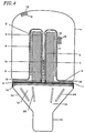
- a bulbous envelope 1 made from the glass has a re-entry cavity 2 with an exhausting tabulation 3 located inside the cavity 2 on its axis (or possibly off axis).
- the tubulation 3 extends from the envelope bottom 4.
- the fill inert gas argon, krypton, or the like
- FIG. 1B is a cross-sectional view of an electrodeless fluorescent lamp shown in FIG. 1A taken along line A-A'.
- a mercury amalgam (or mercury dispenser) 5 is positioned in the tubulation 3 and controls the mercury vapor pressure in the envelope.
- a coil 6 made from multiple strand wire (Litz wire) is wound around a ferrite core 7.
- the ferrite core 7 was made from MnZn material (see U.S. patent Application 09/303,951 by Chamberlain et al.) and is disposed in the re-entry cavity 2.
- the coil 6 and ferrite core 7 are maintained at temperatures below Curie point ( ⁇ 220°C) with the help of a cooling structure made from the metal with high thermal conductivity and low RF power losses (low eddy currents) such as aluminum, copper, or the like.
- the cooling assembly comprises a metal tube 8 positioned inside a ferrite core 7 and the cylinder 9 (cylindrical portion) located inside the Edison socket 10 and having the outer diameter close to that of the inner diameter of Edison socket 10.
- the top edge of the metal tube was positioned inside of the ferrite core where the magnetic field does not have a radial component.
- the coil/ferrite inductance is improved as compared to the case where the top edge of the metal tube 8 is positioned so as to project from the top of the ferrite core 7.
- the term "top edge” is defined as one of two edges of the metal tube 8 which is farther from the Edison socket 10 than the other edge.
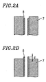
- FIG. 2A shows a state where the top edge of the metal tube 8 is positioned so as not to project from the top of the ferrite core 7 (i.e., where the top edge of the metal tube 8 is inside a hollow portion of the ferrite core 7.)
- FIG. 2B shows a state where the top edge of the metal tube 8 is positioned so as to project from the top of the ferrite core 7 by distance d.
- the coil/ferrite inductance L c was 387.4 ⁇ H
- the resistance component was 0.602 ⁇
- Q quality factor
- the coil/ferrite inductance L c was 384.3 ⁇ H
- the resistance component was 0.794 ⁇
- the quality factor, Q was 303.8.
- the metal tube 8 is thermally coupled to the ferrite core 7.
- the expression “the metal tube 8 is thermally coupled to the ferrite core 7” is defined to simply indicate that the metal tube 8 and the ferrite core 7 are positioned so that heat can be transmitted between the metal tube 8 and the ferrite core 7. This expression is not limited to indicate that the metal tube 8 and the ferrite core 7 are in contact with each other.
- the expression “thermally coupled” is defined to indicate similar states.
- the metal tube 8 and cylinder 9 are welded to each other or made from a single piece. In other words, one end of the metal tube 8 is thermally coupled to the cylinder 9.
- the cylinder 9 is also thermally coupled to the Edison socket 10.
- the heat from the ferrite core 7 and cavity walls 2 is transferred via the metal tube 8 to the cylinder 9 and then dumped to the Edison socket 10.
- the metal tube 8 and the cylinder 9 act as heat conduction means for conducting the heat generated in the ferrite core 7 to the Edison socket 10.
- the Edison socket 10 is connected to a line external to the electrodeless fluorescent lamp in order to receive the power to be supplied to the electrodeless fluorescent lamp, and therefore the heat generated while the electrodeless fluorescent lamp is in use is conducted to the outside of the electrodeless fluorescent lamp through the Edison socket 10.
- the cylinder 9 has a thread which can be coupled to the thread of the Edison socket 10.
- the cylinder 9 and the Edison socket 10 can be coupled to each other through the threads.
- the heat conduction means shown in FIG. 2A in which the top edge of the metal tube 8 is positioned inside the hollow portion of the ferrite core 7 so as to improve the coil/ferrite inductance does not need to have the structure shown in FIG. 1A.
- the heat conduction means can have any other structure as long as it has the function of conducting the heat of the ferrite core 7 to the outside of the electrodeless fluorescent lamp. With these other structures, the heat conduction means can provide the effect of improving the coil/ferrite inductance by positioning the top edge of the metal tube inside the hollow portion of the ferrite core 7, as compared to the case where the top edge of the metal tube projects from the top of the ferrite core 7.
- a tube formed of a ceramic material can be used.
- the tube 8 and the cylinder 9 are preferably formed of a material having a high thermal conductivity and a high resistance, in order to effectively conduct the heat generated in the ferrite core 7 to the Edison socket 10 and restrict the magnetic field from generating an eddy current in the tube 8 and the cylinder 9.
- the tube 8 and the cylinder 9 are preferably formed of a material having a thermal conductivity of 20 W/m ⁇ K or more and a resistance of 2 ⁇ m or more.
- the tube 8 and the cylinder 9 can be formed of a metal material such as, for example, copper or aluminum and/or a ceramic material such as, for example, alumina, aluminum nitride or silicon carbide.
- the ferrite plate 11 is formed of a magnetic material and deforms a magnetic field generated by an electric current flowing through the coil 6.
- the ferrite plate 11 is positioned so that at least a portion of the magnetic flux passing through the ferrite core 7 passes through the ferrite plate 11. In other words, the ferrite plate 11 is magnetically coupled to the ferrite core 7.
- the ferrite plate 11 is, for example, a disc formed of a material identical with the material of the ferrite core 7.
- FIG. 3A schematically shows a magnetic field generated in the vicinity of the ferrite core 7 by an electric current flowing through the coil 6 in the absence of the ferrite plate 11.
- a magnetic flux 50 passes through the cylinder 9 (portion 901).
- the cylinder 9 is formed of a material which can generate an eddy current (for example, a metal material)
- an eddy current is generated in the cylinder 9 by the passage of the magnetic flux 50 through the cylinder 9.
- the coil power loss is generated and the lamp efficacy is reduced.
- the portion of the cylinder 9 in which the eddy current is generated is heated to have its temperature raised.
- the temperature rise of the cylinder 9 has an adverse affect on the lamp driver and the matching network located in an area 13, and moreover reduce the ability of the tube 8 and the cylinder 9 to function as the heat conduction means of conducting the heat generated in the ferrite core 7 to the Edison socket 10.
- FIG. 3B shows that when the ferrite plate 11 is located at the bottom of the ferrite core 7, the magnetic field is deformed.
- the spatial expansion of the magnetic field is smaller and the quantity of the magnetic flux outside the envelope 1 is smaller as a result of the provision of the ferrite plate 11. Therefore, the number of lines of magnetic induction passing through the cylinder 9 is reduced. Since the generation of an eddy current in the cylinder 9 is restricted, the cylinder 9 is prevented from having a high temperature due to the eddy current.
- An eddy current can be generated in a portion 902 of the metal tube 8 shown in FIG. 3A. In the case where the ferrite plate 11 is located at the bottom of the ferrite core 7 as shown in FIG. 3B, the portion 902 of the metal tube 8 can also be restricted from having a high temperature due to the generation of an eddy current.
- the ferrite plate 11 acts as reduction means for reducing a thermal influence of the magnetic field generated by the electric current flowing through the coil 6 exerted on the metal tube 8 and the cylinder 9 (i.e., the heat conduction means).
- the heat conduction means does not need to have the structure shown in FIG. 1A.
- the heat conduction means can have any other structure as long as it has the function of conducting the heat of the ferrite core 7 to the outside of the electrodeless fluorescent lamp. With these other structures of the heat conduction means, the ferrite plate 11 can act as the reduction means for reducing a thermal influence exerted on the heat conduction means.
- the metal tube 8 and the cylinder 9 can be formed of a material having a low resistance.
- Such a broad selection of materials which can be used for the metal tube 8 and the cylinder 9 is preferable in that use of a wider variety of materials having a high thermal conductivity is allowed, resulting in improvement of the function of the metal tube 8 and the cylinder 9 as the heat conduction means.
- the ferrite plate 11 also acts as deformation means for improving the power efficiency and the efficacy of the electrodeless fluorescent lamp by deforming the magnetic field, regardless of the presence or absence of the metal tube 8 and the cylinder 9.
- FIG. 3C schematically shows a magnetic field in the vicinity of the ferrite core 7 of an electrodeless fluorescent lamp which includes neither the tube 8 nor the cylinder 9 forming the heat conduction means, but includes the ferrite plate 11. Due to the provision of the ferrite plate 11, the quantity of the magnetic flux passing through the envelope 1 increases and thus the power efficiency and the efficacy of the electrodeless fluorescent lamp are improved.
- the thermal shield 12 made from non-metallic material and having low thermal conductivity thermally insulates the area 13 from the ferrite core 7 and the ferrite disk 11.
- thermally insulate is defined to include the meaning of "restrict heat transmission”.
- Xydar for example, having a thermal conductivity of about 0.36 W/m ⁇ K is preferably used.
- Xydar is the registered trademark of Amoco Polymers, Inc.
- a material used to form the thermal shield 12 preferably has a thermal conductivity of 0.4 W/m ⁇ K or less.
- the thermal shield 12 acts as restriction means for restricting the heat generated in the ferrite core 7 from being transmitted to the driver.
- the area 13 is used for the disposal of the lamp driver and the matching network (not shown) and is kept at temperature below 100°C.
- the enclosure 14 made from non-metallic material (e.g. plastic) is glued to the lamp bottom 4 and to the Edison socket 10.
- the protective and phosphor coatings 15 and 16 are disposed on the inner surfaces of the envelope 1 and the re-entry cavity 2.
- the reflective coating 17 (alumina or the like) is disposed on the inner surface of the bottom 4 of the envelope 1 and on the inner surface of the cavity 2.
- the outer surface of the bottom 4 and the walls 2 are coated with the reflective coating 18 (alumina or the like).
- a few glass rods 19 are used to position the amalgam 5 inside the tubulation 3. (When the lamp is operated without amalgam, no glass rods are used.)
- To reduce temperature inside the area 13 where the driver and matching network are located a few slits 20 were made in the enclosure 14.
- the second embodiment of the present invention is shown in FIG. 4.
- the cooling arrangement comprises a tube 8 made from material of high thermal conductivity such as alumina, copper, aluminum or the like and a ceramic "skirt" 9 having high thermal conductivity (aluminum oxide, aluminum carbide, or the like).
- the whole cooling structure could be also made from the single piece of ceramic.
- the use of the metal with high thermal conductivity such as copper or aluminum is not desirable due to high losses caused by eddy currents.
- the cooling arrangement is formed of a material having a high resistance.
- the resistance of the material used for the cooling arrangement is preferably equal to or higher than the resistance of copper (2 ⁇ m).
- the material used for the cooling arrangement preferably has a high thermal conductivity.
- the thermal conductivity of the material used for the cooling arrangement is preferably equal to or higher than the thermal conductivity of alumina (20 W/m ⁇ K).
- the cooling arrangement acts as thermal conduction means for releasing the heat generated in the ferrite core 7 to the outside of the electrodeless fluorescent lamp.
- the heat from the ferrite core 7 and the cavity walls 2 is transferred via the tube 8 to the ceramic 9 and then is removed via convection to ambient atmosphere.
- the thermal shield 12 made from the material with low thermal conductivity also helps to reduce heat transfer to the driver area 13 and keeps the temperature in this area below about 100°C.
- slits 20 may be added to the housing unit 14. This however, could be considered optional depending on the lamp operation environment.
- the shape of the envelope 1 is not limited to the shape shown in FIG. 1A or 4.
- the envelope 1 can have a shape without the re-entry cavity 2.
- the envelope 1 can be formed of a ceramic material instead of glass. It is sufficient for the envelope 1 to be at least partially light-transmissive.
- the temperatures of the ferrite core 7, T ferr and inside the area 13, near the thermal shield 12, T base are given in FIG. 5 as functions of the lamp run-up time for the driving frequency of 95 kHz and RF power of 23 W. It is seen that after about 35 min. of operation both temperatures stop to grow.
- the stabilized temperature of the ferrite core 7 is around 175°C that is substantially lower than Curie point of 220°C. Even if the ambient temperature is 40°C the ferrite temperature is still below 220°C.
- the stabilized temperature inside the area 13 is about 85°C so at ambient temperature of 40°C T base is still lower than 100°C.
- the lamp is operated as follows.
- the envelope is filled with argon at pressures from 0.1 to 3.0 Torr (13.3 Pa to 399 Pa) dependent on the envelope diameter and length.
- the mercury vapor pressure in the envelope is controlled by the temperature of the amalgam (or mercury cold spot) 5.
- the 60 Hz line voltage (100 V or 220 V) is applied to the driver located in the area 13.
- the high frequency voltage is generated by the driver and applied to the coil 6 via the matching network.
- the capacitive discharge with low plasma density is ignited at coil voltage around 150-200 V.
- the coil voltage When the coil voltage reaches the magnitude that is high enough to maintain in the envelope a self-sustained inductively coupled discharge, the bright discharge appears in the envelope that is accompanied with the decrease of both coil current and voltage. This is the starting of the lamp.
- the magnitudes of the coil starting voltage and current are determined by the coil number of turns, gas/mercury vapor pressure in the envelope and the envelope geometry.
- the inert gas (argon) pressure in the envelope 1 was about 1 torr (about 133 Pa).
- the envelope diameter is 60 mm and the envelope length is 62 mm.
- the induction coil 6 has 60 turns wound in two layers.
- the lamp starting voltage was 1000 V rms.
- the coil voltage and current, V m and I m needed to maintain the inductively coupled discharge decrease as RF power grows.
- V m the typical coil maintaining voltage
- V m varied from 480 V at 15 W to 350 V at 40 W
- the coil current I m varied from 2.3 A (15 w) to 1.6 A (40 W).
- the lamp power efficiency during the lamp operation depends on the coil and ferrite core power losses, P loss .
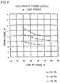
- the power losses measured in the lamp shown in FIG. 1A (the first embodiment) are plotted as functions of the lamp power, P lamp , in FIG. 6 for three driving frequencies: 101 kHz, 135 kHz and 170 kHz.
- the power losses were determined as the difference between the lamp forward power, P f , and reflected power, P ref , measured for the coil current I m but in the absence of the RF discharge in the lamp.
- the increase of the driving frequency leads to lower coil/ferrite power losses. For instance, at the frequency of 170 kHz and the lamps RF power of 23 W, the coil/ferrite power losses are 2.4 W.
- the lamp power efficiency, ⁇ and the lamp efficacy (LPW) are shown in FIG. 7 as functions of the driving frequency, f, for the lamp described in FIG.
- the present invention is not limited to be applicable to an electrodeless fluorescent lamp.
- the present invention is applicable to an electrodeless lamp in which the inner wall of the envelope 1 (FIG. 1A and FIG. 4) is not coated with the phosphor coating 16 and thus light by discharge is directly released to the outside of the envelope 1, based on a similar principle to the above-described operational principle.
Landscapes
- Physics & Mathematics (AREA)
- Electromagnetism (AREA)
- Engineering & Computer Science (AREA)
- Plasma & Fusion (AREA)
- Discharge Lamps And Accessories Thereof (AREA)
- Non-Portable Lighting Devices Or Systems Thereof (AREA)
Abstract
An electrodeless lamp includes an envelope (1)
containing a fill of discharge gas; a magnetic core (7);
an induction coil (6) wound around the magnetic core (7);
a driver for supplying an electric current to the induction
coil (6) to drive the electrodeless lamp; a socket (10) for
receiving a power supplied to the electrodeless lamp; and
heat conduction means (8, 9) thermally coupled to the
magnetic core (7) and the socket (10) for conducting heat
generated in the magnetic core (7) to the socket (10).

Description
The invention relates to electric lamps and, more
specifically, to electrodeless lamps operated at
frequencies from 20 kHz to 1 MHz.
Electrodeless fluorescent lamps have been recently
introduced in markets for indoor, outdoor, industrial, and
commercial applications. The advantage of electrodeless
lamps is the removal of internal electrodes and heating
filaments that are a life-limiting factor of conventional
fluorescent lamps. Therefore, the life of electrodeless
fluorescent lamps is substantially higher than that of
conventional fluorescent lamps and can reach 100,000 hrs.
An electrodeless fluorescent lamp introduced in the
market by General Electric Corp. ("Genura") is operated at
a frequency of 2.65 MHz and used for indoor general lighting.
This lamp is a replacement for a R30 incandescent lamp and
has 1,100 lumen light output at 23 W of total power. The
life of the Genura lamp, 15,000 hrs, is much longer than
that of the incandescent lamp. The drawback of the Genura
lamp is the high initial cost, partially due to the need
to prevent electromagnetic interference and partially due
to the circuit cost operating at 2.65 MHz. Both drawbacks
could be diminished if the electrodeless fluorescent lamp
was operated at low frequency as low as 100 kHz.
In U.S. Patent Applications 09/083,820 by Popov et
al. and 09/303,951 by Chamberlain et al. (upon on which the
present application claims priority and which has the same
assignee as the present application) electrodeless
fluorescent lamps operated at low frequencies from 50 kHz
to 500 kHz were described. Those lamps utilized a ferrite
core made from MnZn material, Litz wire, and an aluminum
cooling structure that removed heat from the reentry cavity
walls and ferrite core and redirected heat to the lamp
fixture. The aluminum cooling structure comprises the
aluminum cylinder inside the ferrite core and the aluminum
base welded to the lamp fixture. This approach and
construction were found to be very effective to keep the
ferrite core at temperature below Curie point.
However, in many lamp applications (e.g. the
replacement of a conventional incandescent lamp) the large
and heavy metal (aluminum or copper) base is not suitable
due to its large size and weight. Also, the replacement of
the incandescent lamp requires the use of Edison socket that
should be coupled with the base. Again, the diameter of the
lamp base should not be larger than the diameter of the
incandescent lamp bulb that is 60 mm.
The proximity of ferrite core to the metal base
causes the interference of the magnetic field with the metal
base that results in the increase of the coil/ferrite core
power losses. Indeed, the magnetic field generated by the
coil induces eddy currents in the metal base that causes
power losses and reduces the combined coil/structure
quality factor, Q. As a result, the lamp power efficiency
and hence, efficacy decreases.
The need for the incorporation of the lamp driver
and lamp matching network inside the lamp base and to couple
them with the Edison socket makes the cooling issue more
complex. Indeed, the temperature inside of the lamp base
should not exceed - 100°C to provide integrity of the driver's
components. The use of components that can stand higher
temperatures leads to higher cost of the driver and hence,
the lamp.
The present invention comprises an electrodeless
fluorescent lamp that includes a glass envelope containing
a fill of discharge gas (for example, a mixture of inert
gas and mercury vapor). A ferrite core and an induction coil
made from Litz wire are positioned inside of the reentrant
cavity. A cooling structure comprises a metal (aluminum,
copper) tube placed inside of the cavity and a ceramic
cylinder that is thermally coupled to the Edison socket with
material having high thermal conductivity.
An objective of the present invention is to provide
a cooling structure that keeps the ferrite core temperature
below Curie point.
Another objective of the present invention is to
provide low temperatures, T < 100°C, inside of the lamp base
where the driver and matching network are placed.
A further objective of the present invention is to
provide low power losses in the cooling structure and in
the lamp base so to provide a high lamp power efficiency
and efficacy.
Yet another objective of the present invention is
to design a coil that has high quality factor at the frequency
as low as 100 kHz so as to provide low coil power losses
and high lamp power efficiency.
An additional objective of the present invention is
to provide an electrodeless fluorescent lamp that can
operate at 100 kHz that results in overall low cost system.
Referring to FIG. 1A, a bulbous envelope 1 made from
the glass has a re-entry cavity 2 with an exhausting
tabulation 3 located inside the cavity 2 on its axis (or
possibly off axis). The tubulation 3 extends from the
envelope bottom 4. The fill inert gas (argon, krypton, or
the like) is at pressure from 0.1 torr to 5 torr (13.3 Pa
to 665 Pa). FIG. 1B is a cross-sectional view of an
electrodeless fluorescent lamp shown in FIG. 1A taken along
line A-A'.
A mercury amalgam (or mercury dispenser) 5 is
positioned in the tubulation 3 and controls the mercury vapor
pressure in the envelope. A coil 6 made from multiple strand
wire (Litz wire) is wound around a ferrite core 7. The ferrite
core 7 was made from MnZn material (see U.S. patent
Application 09/303,951 by Chamberlain et al.) and is
disposed in the re-entry cavity 2. The coil 6 and ferrite
core 7 are maintained at temperatures below Curie point
(<220°C) with the help of a cooling structure made from the
metal with high thermal conductivity and low RF power losses
(low eddy currents) such as aluminum, copper, or the like.
The cooling assembly comprises a metal tube 8 positioned
inside a ferrite core 7 and the cylinder 9 (cylindrical
portion) located inside the Edison socket 10 and having the
outer diameter close to that of the inner diameter of Edison
socket 10.
To minimize the effect of the metal tube on the
coil/ferrite inductance, the top edge of the metal tube was
positioned inside of the ferrite core where the magnetic
field does not have a radial component. By positioning the
top edge of the metal tube 8 in this manner, the coil/ferrite
inductance is improved as compared to the case where the
top edge of the metal tube 8 is positioned so as to project
from the top of the ferrite core 7. Herein, the term "top
edge" is defined as one of two edges of the metal tube 8
which is farther from the Edison socket 10 than the other
edge.
FIG. 2A shows a state where the top edge of the metal
tube 8 is positioned so as not to project from the top of
the ferrite core 7 (i.e., where the top edge of the metal
tube 8 is inside a hollow portion of the ferrite core 7.)
FIG. 2B shows a state where the top edge of the metal tube
8 is positioned so as to project from the top of the ferrite
core 7 by distance d. In the case where the top edge of the
metal tube 8 was positioned as shown in FIG. 2A, the
coil/ferrite inductance Lc was 387.4 µH, the resistance
component was 0.602 Ω, and the quality factor, Q was 404.2.
In the case where the top edge of the metal tube 8 was
positioned as shown in FIG. 2B and d = 5 mm, the coil/ferrite
inductance Lc was 384.3 µH, the resistance component was
0.794 Ω, and the quality factor, Q was 303.8. As can be
appreciated, when the top edge of the metal tube 8 projects
from the top of the ferrite core 7, the coil/ferrite
inductance decreases and the resistance component increases.
Therefore, the coil power loss increases. Furthermore, the
metal tube 8 is undesirably heated to a high temperature
by an eddy current generated in the projecting portion of
the metal tube 8.
The metal tube 8 is thermally coupled to the ferrite
core 7. Herein, the expression "the metal tube 8 is
thermally coupled to the ferrite core 7" is defined to simply
indicate that the metal tube 8 and the ferrite core 7 are
positioned so that heat can be transmitted between the metal
tube 8 and the ferrite core 7. This expression is not limited
to indicate that the metal tube 8 and the ferrite core 7
are in contact with each other. Throughout this
specification, the expression "thermally coupled" is
defined to indicate similar states.
The metal tube 8 and cylinder 9 are welded to each
other or made from a single piece. In other words, one end
of the metal tube 8 is thermally coupled to the cylinder
9.
The cylinder 9 is also thermally coupled to the
Edison socket 10. Thus, the heat from the ferrite core 7
and cavity walls 2 is transferred via the metal tube 8 to
the cylinder 9 and then dumped to the Edison socket 10.
As can be appreciated, the metal tube 8 and the
cylinder 9 act as heat conduction means for conducting the
heat generated in the ferrite core 7 to the Edison socket
10. The Edison socket 10 is connected to a line external
to the electrodeless fluorescent lamp in order to receive
the power to be supplied to the electrodeless fluorescent
lamp, and therefore the heat generated while the
electrodeless fluorescent lamp is in use is conducted to
the outside of the electrodeless fluorescent lamp through
the Edison socket 10.
The cylinder 9 has a thread which can be coupled to
the thread of the Edison socket 10. The cylinder 9 and the
Edison socket 10 can be coupled to each other through the
threads.
The heat conduction means shown in FIG. 2A in which
the top edge of the metal tube 8 is positioned inside the
hollow portion of the ferrite core 7 so as to improve the
coil/ferrite inductance does not need to have the structure
shown in FIG. 1A. The heat conduction means can have any
other structure as long as it has the function of conducting
the heat of the ferrite core 7 to the outside of the
electrodeless fluorescent lamp. With these other
structures, the heat conduction means can provide the effect
of improving the coil/ferrite inductance by positioning the
top edge of the metal tube inside the hollow portion of the
ferrite core 7, as compared to the case where the top edge
of the metal tube projects from the top of the ferrite core
7.
Instead of the metal tube 8, a tube formed of a
ceramic material can be used. The tube 8 and the cylinder
9 are preferably formed of a material having a high thermal
conductivity and a high resistance, in order to effectively
conduct the heat generated in the ferrite core 7 to the Edison
socket 10 and restrict the magnetic field from generating
an eddy current in the tube 8 and the cylinder 9.
Specifically, the tube 8 and the cylinder 9 are preferably
formed of a material having a thermal conductivity of
20 W/m·K or more and a resistance of 2 Ω·m or more. The
tube 8 and the cylinder 9 can be formed of a metal material
such as, for example, copper or aluminum and/or a ceramic
material such as, for example, alumina, aluminum nitride
or silicon carbide.
The ferrite plate 11 increases the coil/ferrite
effective permeability, µaff, and the coil/ferrite
inductance, Lc, that results in the increase of the
coil/ferrite quality factor, Q (Q = 550 at f = 100 kHz),
and in the decrease of the coil/ferrite power losses, Ploss.
Consequently, the lamp has high power efficiency, (η =Ppl/Plamp
= (Plamp - Ploss)/Plamp) and high efficacy.
The ferrite plate 11 is formed of a magnetic material
and deforms a magnetic field generated by an electric current
flowing through the coil 6. The ferrite plate 11 is
positioned so that at least a portion of the magnetic flux
passing through the ferrite core 7 passes through the ferrite
plate 11. In other words, the ferrite plate 11 is
magnetically coupled to the ferrite core 7.
The ferrite plate 11 is, for example, a disc formed
of a material identical with the material of the ferrite
core 7.
FIG. 3A schematically shows a magnetic field
generated in the vicinity of the ferrite core 7 by an electric
current flowing through the coil 6 in the absence of the
ferrite plate 11. As shown in FIG. 3A, in the absence of
the ferrite plate 11, a magnetic flux 50 passes through the
cylinder 9 (portion 901). When the cylinder 9 is formed of
a material which can generate an eddy current (for example,
a metal material), an eddy current is generated in the
cylinder 9 by the passage of the magnetic flux 50 through
the cylinder 9. Thus, the coil power loss is generated and
the lamp efficacy is reduced. The portion of the cylinder
9 in which the eddy current is generated is heated to have
its temperature raised. The temperature rise of the
cylinder 9 has an adverse affect on the lamp driver and the
matching network located in an area 13, and moreover reduce
the ability of the tube 8 and the cylinder 9 to function
as the heat conduction means of conducting the heat generated
in the ferrite core 7 to the Edison socket 10.
FIG. 3B shows that when the ferrite plate 11 is
located at the bottom of the ferrite core 7, the magnetic
field is deformed. In FIG. 3B, as compared with in FIG. 3A,
the spatial expansion of the magnetic field is smaller and
the quantity of the magnetic flux outside the envelope 1
is smaller as a result of the provision of the ferrite plate
11. Therefore, the number of lines of magnetic induction
passing through the cylinder 9 is reduced. Since the
generation of an eddy current in the cylinder 9 is restricted,
the cylinder 9 is prevented from having a high temperature
due to the eddy current. An eddy current can be generated
in a portion 902 of the metal tube 8 shown in FIG. 3A. In
the case where the ferrite plate 11 is located at the bottom
of the ferrite core 7 as shown in FIG. 3B, the portion 902
of the metal tube 8 can also be restricted from having a
high temperature due to the generation of an eddy current.
As can be appreciated, the ferrite plate 11 acts as
reduction means for reducing a thermal influence of the
magnetic field generated by the electric current flowing
through the coil 6 exerted on the metal tube 8 and the
cylinder 9 (i.e., the heat conduction means). The heat
conduction means does not need to have the structure shown
in FIG. 1A. The heat conduction means can have any other
structure as long as it has the function of conducting the
heat of the ferrite core 7 to the outside of the electrodeless
fluorescent lamp. With these other structures of the heat
conduction means, the ferrite plate 11 can act as the
reduction means for reducing a thermal influence exerted
on the heat conduction means.
Since the provision of the ferrite plate 11 can
prevent the generation of an eddy current in the metal tube
8 and the cylinder 9, the metal tube 8 and the cylinder 9
can be formed of a material having a low resistance. Such
a broad selection of materials which can be used for the
metal tube 8 and the cylinder 9 is preferable in that use
of a wider variety of materials having a high thermal
conductivity is allowed, resulting in improvement of the
function of the metal tube 8 and the cylinder 9 as the heat
conduction means.
The ferrite plate 11 also acts as deformation means
for improving the power efficiency and the efficacy of the
electrodeless fluorescent lamp by deforming the magnetic
field, regardless of the presence or absence of the metal
tube 8 and the cylinder 9.
FIG. 3C schematically shows a magnetic field in the
vicinity of the ferrite core 7 of an electrodeless
fluorescent lamp which includes neither the tube 8 nor the
cylinder 9 forming the heat conduction means, but includes
the ferrite plate 11. Due to the provision of the ferrite
plate 11, the quantity of the magnetic flux passing through
the envelope 1 increases and thus the power efficiency and
the efficacy of the electrodeless fluorescent lamp are
improved.
The thermal shield 12 made from non-metallic
material and having low thermal conductivity thermally
insulates the area 13 from the ferrite core 7 and the ferrite
disk 11. Herein, the expression "thermally insulate" is
defined to include the meaning of "restrict heat
transmission". For the thermal shield 12, Xydar, for
example, having a thermal conductivity of about 0.36 W/m·K
is preferably used. "Xydar" is the registered trademark of
Amoco Polymers, Inc. A material used to form the thermal
shield 12 preferably has a thermal conductivity of 0.4 W/m·K
or less.
The thermal shield 12 acts as restriction means for
restricting the heat generated in the ferrite core 7 from
being transmitted to the driver.
The area 13 is used for the disposal of the lamp
driver and the matching network (not shown) and is kept at
temperature below 100°C. The enclosure 14 made from
non-metallic material (e.g. plastic) is glued to the lamp
bottom 4 and to the Edison socket 10. The protective and
phosphor coatings 15 and 16 are disposed on the inner
surfaces of the envelope 1 and the re-entry cavity 2. The
reflective coating 17 (alumina or the like) is disposed on
the inner surface of the bottom 4 of the envelope 1 and on
the inner surface of the cavity 2. To minimize visible light
losses via the bottom 4 and the cavity walls 2 the outer
surface of the bottom 4 and the walls 2 are coated with the
reflective coating 18 (alumina or the like). A few glass
rods 19 are used to position the amalgam 5 inside the
tubulation 3. (When the lamp is operated without amalgam,
no glass rods are used.) To reduce temperature inside the
area 13 where the driver and matching network are located
a few slits 20 were made in the enclosure 14.
The second embodiment of the present invention is
shown in FIG. 4. The cooling arrangement comprises a tube
8 made from material of high thermal conductivity such as
alumina, copper, aluminum or the like and a ceramic "skirt"
9 having high thermal conductivity (aluminum oxide,
aluminum carbide, or the like). The whole cooling structure
could be also made from the single piece of ceramic. The
use of the metal with high thermal conductivity such as
copper or aluminum is not desirable due to high losses caused
by eddy currents. In order to prevent a large eddy current
from being generated in the cooling arrangement, it is
preferable that the cooling arrangement is formed of a
material having a high resistance. The resistance of the
material used for the cooling arrangement is preferably
equal to or higher than the resistance of copper (2 Ω·m).
In order to remove the heat from the ferrite core 7, the
material used for the cooling arrangement preferably has
a high thermal conductivity. The thermal conductivity of
the material used for the cooling arrangement is preferably
equal to or higher than the thermal conductivity of alumina
(20 W/m·K).
The cooling arrangement acts as thermal conduction
means for releasing the heat generated in the ferrite core
7 to the outside of the electrodeless fluorescent lamp.
The heat from the ferrite core 7 and the cavity walls
2 is transferred via the tube 8 to the ceramic 9 and then
is removed via convection to ambient atmosphere. The
thermal shield 12 made from the material with low thermal
conductivity also helps to reduce heat transfer to the driver
area 13 and keeps the temperature in this area below about
100°C.
In order to further reduce the temperature of the
electronic components in the area 13, slits 20 may be added
to the housing unit 14. This however, could be considered
optional depending on the lamp operation environment.
In the second embodiment shown in FIG. 4, it is
preferable to position the top edge of the tube 8 inside
the hollow portion of the ferrite core 7 as in the first
embodiment.
In the first and second embodiments, the shape of
the envelope 1 is not limited to the shape shown in FIG. 1A
or 4. For example, the envelope 1 can have a shape without
the re-entry cavity 2. The envelope 1 can be formed of a
ceramic material instead of glass. It is sufficient for the
envelope 1 to be at least partially light-transmissive.
The temperatures of the ferrite core 7, Tferr and
inside the area 13, near the thermal shield 12, Tbase are given
in FIG. 5 as functions of the lamp run-up time for the driving
frequency of 95 kHz and RF power of 23 W. It is seen that
after about 35 min. of operation both temperatures stop to
grow. The stabilized temperature of the ferrite core 7 is
around 175°C that is substantially lower than Curie point
of 220°C. Even if the ambient temperature is 40°C the ferrite
temperature is still below 220°C. The stabilized
temperature inside the area 13 is about 85°C so at ambient
temperature of 40°C Tbase is still lower than 100°C.
The lamp is operated as follows. The envelope is
filled with argon at pressures from 0.1 to 3.0 Torr (13.3 Pa
to 399 Pa) dependent on the envelope diameter and length.
The mercury vapor pressure in the envelope is controlled
by the temperature of the amalgam (or mercury cold spot)
5. The 60 Hz line voltage (100 V or 220 V) is applied to
the driver located in the area 13. The high frequency
voltage is generated by the driver and applied to the coil
6 via the matching network. The capacitive discharge with
low plasma density is ignited at coil voltage around 150-200
V.
When the coil voltage reaches the magnitude that is
high enough to maintain in the envelope a self-sustained
inductively coupled discharge, the bright discharge appears
in the envelope that is accompanied with the decrease of
both coil current and voltage. This is the starting of the
lamp. The magnitudes of the coil starting voltage and current
are determined by the coil number of turns, gas/mercury vapor
pressure in the envelope and the envelope geometry.
In the preferred embodiments 1 and 2 the inert gas
(argon) pressure in the envelope 1 was about 1 torr (about
133 Pa). The envelope diameter is 60 mm and the envelope
length is 62 mm. The induction coil 6 has 60 turns wound
in two layers. The lamp starting voltage was 1000 V rms.
The coil voltage and current, Vm and Im, needed to maintain
the inductively coupled discharge decrease as RF power grows.
For the coil with 60 turns the typical coil maintaining
voltage Vm, varied from 480 V at 15 W to 350 V at 40 W and
the coil current Im, varied from 2.3 A (15 w) to 1.6 A (40
W).
The lamp power efficiency during the lamp operation
depends on the coil and ferrite core power losses, Ploss. The
power losses measured in the lamp shown in FIG. 1A (the first
embodiment) are plotted as functions of the lamp power, Plamp,
in FIG. 6 for three driving frequencies: 101 kHz, 135 kHz
and 170 kHz. The power losses were determined as the
difference between the lamp forward power, Pf, and reflected
power, Pref, measured for the coil current Im but in the
absence of the RF discharge in the lamp.
It is seen from FIG. 6 that as the lamp RF power
increases, the coil/ferrite power losses, Ploss, decreases.
For instance, for the frequency of 101 kHz, the power losses
decreases from 5.6 W at Plamp = 19.5 W to 3.8 W at Plamp = 26 W.
The increase of the driving frequency leads to lower
coil/ferrite power losses. For instance, at the frequency
of 170 kHz and the lamps RF power of 23 W, the coil/ferrite
power losses are 2.4 W. The decrease of Ploss at higher
frequencies results in higher lamp power efficiency, η =
Ppl/Plamp. The lamp power efficiency, η and the lamp efficacy
(LPW) are shown in FIG. 7 as functions of the driving
frequency, f, for the lamp described in FIG. 1A (the first
embodiment) and operated at lamp RF power of 23 W. It is
seen that η increases as the driving frequency increases
from 0.81 at f = 101 kHz to 0.9 at f = 170 kHz. It is expected
that the lamp efficacy also increases with the driving
frequency. Indeed, as it is shown in FIG. 7 the lamp efficacy
increases from 65 LPW at f = 101 kHz to 73 LPW at f = 170
kHz.
It should be mentioned here that the efficacy of the
lamp described in the present invention and operated at the
frequency as low as 100 kHz is higher than that of Genura
electrodeless fluorescent lamp operated at the same RF power
but at substantially higher driving frequency of 2.65 MHz.
The present invention is not limited to be
applicable to an electrodeless fluorescent lamp. For
example, the present invention is applicable to an
electrodeless lamp in which the inner wall of the envelope
1 (FIG. 1A and FIG. 4) is not coated with the phosphor coating
16 and thus light by discharge is directly released to the
outside of the envelope 1, based on a similar principle to
the above-described operational principle.
While it is apparent that change and modifications
can be made within the spirit and scope of the present
invention, it is our intention, however, only to be limited
by the appended claims.
Claims (18)
- An electrodeless lamp, comprising:an envelope containing a fill of discharge gas;a magnetic core;an induction coil wound around the magnetic core;a driver for supplying an electric current to the induction coil to drive the electrodeless lamp;a socket for receiving a power supplied to the electrodeless lamp; andheat conduction means thermally coupled to the magnetic core and the socket for conducting heat generated in the magnetic core to the socket.
- An electrodeless lamp according to claim 1, wherein the envelope has a re-entry cavity, and the magnetic core is positioned to be adjacent to the re-entry cavity.
- An electrodeless lamp according to claim 1, wherein:the magnetic core has a hollow portion;the heat conduction means includes a tube and a cylindrical portion thermally coupled to the tube; andat least a portion of the tube is positioned inside the hollow portion, and the cylindrical portion is thermally coupled to the socket.
- An electrodeless lamp according to claim 1, wherein the heat conduction means is formed of a material having a thermal conductivity of 20 W/m·K or higher and a resistance of 2 Ω·m or higher.
- An electrodeless lamp according to claim 1, wherein the heat conduction means is formed of at least one of a metal material and a ceramic material.
- An electrodeless lamp according to claim 5, wherein the metal material includes at least one of copper and aluminum.
- An electrodeless lamp according to claim 5, wherein the ceramic material includes at least one of alumina, aluminum nitride, and silicon carbide.
- An electrodeless lamp according to claim 3, wherein the socket has a first thread, and the cylindrical portion has a second thread which can be coupled to the first thread.
- An electrodeless lamp according to claim 3, wherein one end of the tube is thermally coupled to the cylindrical portion, and the other end of the tube is positioned inside the hollow portion of the magnetic core.
- An electrodeless lamp, comprising:an envelope containing a fill of discharge gas;a magnetic core;an induction coil wound around the magnetic core;a driver for supplying an electric current to the induction coil to drive the electrodeless lamp; andrestriction means for restricting heat generated in the magnetic core from being transmitted to the driver.
- An electrodeless lamp according to claim 10, wherein the restriction means is formed of a material having a thermal conductivity of 0.4 W/m·K or less.
- An electrodeless lamp, comprising:an envelope containing a fill of discharge gas;a magnetic core;an induction coil wound around the magnetic core;a driver for supplying an electric current to the induction coil to drive the electrodeless lamp; anddeformation means magnetically coupled to the magnetic core for deforming a magnetic field generated by an electric current flowing through the induction coil so as to increase a quantity of a magnetic flux passing through the envelope.
- An electrodeless lamp according to claim 12, wherein the deformation means includes a disc formed of a magnetic material which is magnetically coupled to the magnetic core.
- An electrodeless lamp according to claim 13, wherein the magnetic material is identical with a material of the magnetic core.
- An electrodeless lamp, comprising:an envelope containing a fill of discharge gas;a magnetic core;an induction coil wound around the magnetic core;a driver for supplying an electric current to the induction coil to drive the electrodeless lamp;heat conduction means thermally coupled to the magnetic core for conducting heat generated in the magnetic core to the outside of the electrodeless lamp; andreduction means magnetically coupled to the magnetic core for reducing a thermal influence of a magnetic field generated by an electric current flowing through the induction coil exerted on the heat conduction means.
- An electrodeless lamp according to claim 15, wherein the reduction means includes a disc formed of a magnetic material which is magnetically coupled to the magnetic core.
- An electrodeless lamp according to claim 16, wherein the magnetic material is identical with a material of the magnetic core.
- An electrodeless lamp, comprising:wherein:an envelope containing a fill of discharge gas;a magnetic core having a hollow portion;an induction coil wound around the magnetic core;a driver for supplying an electric current to the induction coil to drive the electrodeless lamp; andheat conduction means thermally coupled to the magnetic core for conducting heat generated in the magnetic core to the outside of the electrodeless lamp,the heat conduction means includes a tube thermally coupled to the magnetic core, andone end of the tube is positioned inside the hollow portion.
Applications Claiming Priority (3)
| Application Number | Priority Date | Filing Date | Title |
|---|---|---|---|
| US435960 | 1999-11-09 | ||
| US09/435,960 US6433478B1 (en) | 1999-11-09 | 1999-11-09 | High frequency electrodeless compact fluorescent lamp |
| PCT/JP2000/007858 WO2001035446A1 (en) | 1999-11-09 | 2000-11-08 | Electrodeless lamp |
Publications (2)
| Publication Number | Publication Date |
|---|---|
| EP1235255A1 true EP1235255A1 (en) | 2002-08-28 |
| EP1235255A4 EP1235255A4 (en) | 2006-05-03 |
Family
ID=23730529
Family Applications (1)
| Application Number | Title | Priority Date | Filing Date |
|---|---|---|---|
| EP00974838A Withdrawn EP1235255A4 (en) | 1999-11-09 | 2000-11-08 | LAMP WITHOUT ELECTRODE |
Country Status (6)
| Country | Link |
|---|---|
| US (2) | US6433478B1 (en) |
| EP (1) | EP1235255A4 (en) |
| CN (2) | CN1222012C (en) |
| CA (1) | CA2390234A1 (en) |
| TW (1) | TW472283B (en) |
| WO (1) | WO2001035446A1 (en) |
Cited By (1)
| Publication number | Priority date | Publication date | Assignee | Title |
|---|---|---|---|---|
| DE102005050306B3 (en) * | 2005-10-20 | 2007-03-15 | Minebea Co., Ltd. | Electrode-less high frequency low-pressure gas discharge lamp has soft magnetic core for inductive conversion with exciter winding and discharge unit |
Families Citing this family (31)
| Publication number | Priority date | Publication date | Assignee | Title |
|---|---|---|---|---|
| US6433478B1 (en) * | 1999-11-09 | 2002-08-13 | Matsushita Electric Industrial Co., Ltd. | High frequency electrodeless compact fluorescent lamp |
| US6555954B1 (en) * | 2000-07-14 | 2003-04-29 | Matsushita Electric Industrial Co., Ltd. | Compact electrodeless fluorescent lamp with improved cooling |
| US6653783B2 (en) * | 2000-09-26 | 2003-11-25 | Matsushita Electric Industrial Co., Ltd. | Self-ballasted electrodeless discharge lamp with startability improving means |
| US6979940B2 (en) * | 2002-05-28 | 2005-12-27 | Matsushita Electric Industrial Co., Ltd. | Electrodeless discharge lamp |
| JP2005346924A (en) * | 2002-06-03 | 2005-12-15 | Matsushita Electric Ind Co Ltd | Electrodeless discharge lamp lighting device and bulb-type electrodeless fluorescent lamp |
| WO2004006289A1 (en) * | 2002-07-02 | 2004-01-15 | Matsushita Electric Industrial Co., Ltd. | Bulb type electrodeless discharge lamp and electrodeless discharge lamp lighting device |
| US7778712B1 (en) * | 2003-01-13 | 2010-08-17 | Success by Association, Inc. | Bulb apparatus |
| US20050164630A1 (en) * | 2003-11-19 | 2005-07-28 | Lawrence Kates | Repeater unit with flourescent ballast |
| JP4258380B2 (en) * | 2004-01-05 | 2009-04-30 | パナソニック電工株式会社 | Electrodeless fluorescent lamp and its lighting device |
| TWI272578B (en) * | 2004-08-03 | 2007-02-01 | Lite On It Corp | Disk drive structure with an adjustable bearing structure for guide bars |
| US20060076864A1 (en) * | 2004-10-13 | 2006-04-13 | Matsushita Electric Works Ltd. | Electrodeless high power fluorescent lamp with controlled coil temperature |
| US7279840B2 (en) * | 2004-11-17 | 2007-10-09 | Matsushita Electric Works Ltd. | Electrodeless fluorescent lamp with controlled cold spot temperature |
| US7088033B2 (en) * | 2004-11-24 | 2006-08-08 | Matsushita Electric Works Ltd. | Electrodeless fluorescent lamp with stabilized operation at high and low ambient temperatures |
| RU2389108C2 (en) * | 2004-12-27 | 2010-05-10 | Серавижн Лимитед | Nonelectrode incandescent lamp |
| US8102123B2 (en) * | 2005-10-04 | 2012-01-24 | Topanga Technologies, Inc. | External resonator electrode-less plasma lamp and method of exciting with radio-frequency energy |
| KR100764778B1 (en) | 2005-12-12 | 2007-10-11 | 엘지전자 주식회사 | Communication device and method using electrodeless lamp system |
| US20080258629A1 (en) * | 2007-04-20 | 2008-10-23 | Rensselaer Polytechnic Institute | Apparatus and method for extracting power from and controlling temperature of a fluorescent lamp |
| DE102007042978A1 (en) * | 2007-09-10 | 2009-03-12 | Osram Gesellschaft mit beschränkter Haftung | lamp |
| US8702465B2 (en) * | 2008-05-07 | 2014-04-22 | Ceravision Limited | Method of manufacturing an electrode-less incandescent bulb |
| CN101315866B (en) * | 2008-07-03 | 2011-08-03 | 张誉耀 | Electrodeless lamp equipped with ventilation, heat insulation and heat radiation device |
| CN102135255B (en) * | 2011-03-09 | 2013-07-10 | 浙江开元光电照明科技有限公司 | Electrodeless-bulb table lamp with power between 15W and 25W |
| US8847473B2 (en) * | 2011-09-01 | 2014-09-30 | Lianying YE | Self-cooling screw bulb-type electromagnetic induction lamp |
| US8502482B1 (en) * | 2011-12-06 | 2013-08-06 | John Yeh | Compact induction lamp |
| CN102931049B (en) * | 2012-10-18 | 2016-04-06 | 杭州新叶光电工程技术有限公司 | A kind of compact electrodeless fluorescent lamp |
| US10529551B2 (en) | 2012-11-26 | 2020-01-07 | Lucidity Lights, Inc. | Fast start fluorescent light bulb |
| US20140375203A1 (en) | 2012-11-26 | 2014-12-25 | Lucidity Lights, Inc. | Induction rf fluorescent lamp with helix mount |
| US10128101B2 (en) * | 2012-11-26 | 2018-11-13 | Lucidity Lights, Inc. | Dimmable induction RF fluorescent lamp with reduced electromagnetic interference |
| US10141179B2 (en) | 2012-11-26 | 2018-11-27 | Lucidity Lights, Inc. | Fast start RF induction lamp with metallic structure |
| USD854198S1 (en) | 2017-12-28 | 2019-07-16 | Lucidity Lights, Inc. | Inductive lamp |
| US10236174B1 (en) | 2017-12-28 | 2019-03-19 | Lucidity Lights, Inc. | Lumen maintenance in fluorescent lamps |
| CN113451955B (en) * | 2021-07-08 | 2022-06-24 | 中国工程物理研究院总体工程研究所 | Device and method for installing sensor lead in narrow space through wire protection |
Family Cites Families (40)
| Publication number | Priority date | Publication date | Assignee | Title |
|---|---|---|---|---|
| US3987334A (en) * | 1975-01-20 | 1976-10-19 | General Electric Company | Integrally ballasted electrodeless fluorescent lamp |
| JPS5858782B2 (en) * | 1976-09-10 | 1983-12-27 | 株式会社東芝 | fluorescent light |
| JPS5346182A (en) * | 1976-10-08 | 1978-04-25 | Toshiba Corp | Bulb type fluorescent discharge lamp |
| US4298828A (en) * | 1979-02-21 | 1981-11-03 | Westinghouse Electric Corp. | High frequency electrodeless lamp having a gapped magnetic core and method |
| US4357559A (en) * | 1980-03-17 | 1982-11-02 | General Electric Company | Fluorescent lamp utilizing phosphor combination |
| NL8104223A (en) | 1981-09-14 | 1983-04-05 | Philips Nv | ELECTRESSLESS GAS DISCHARGE LAMP. |
| NL8401878A (en) * | 1984-06-14 | 1986-01-02 | Philips Nv | ELECTRESSLESS LOW PRESSURE DISCHARGE LAMP. |
| NL8900406A (en) * | 1989-02-20 | 1990-09-17 | Philips Nv | ELECTRESSLESS LOW PRESSURE DISCHARGE LAMP. |
| ES2075324T3 (en) * | 1990-04-06 | 1995-10-01 | Philips Electronics Nv | LOW PRESSURE DISCHARGE LAMP WITHOUT ELECTRODES. |
| US5291091A (en) * | 1991-01-25 | 1994-03-01 | U.S. Philips Corporation | Electrodeless low-pressure discharge |
| US5306555A (en) * | 1991-09-18 | 1994-04-26 | Battelle Memorial Institute | Aerogel matrix composites |
| US5355054A (en) * | 1992-01-07 | 1994-10-11 | U.S. Philips Corporation | Electrodeless low-pressure discharge lamp having a cooling body with a partitioned vapor channel |
| US5581157A (en) * | 1992-05-20 | 1996-12-03 | Diablo Research Corporation | Discharge lamps and methods for making discharge lamps |
| US5572083A (en) * | 1992-07-03 | 1996-11-05 | U.S. Philips Corporation | Electroless low-pressure discharge lamp |
| US5343126A (en) | 1992-10-26 | 1994-08-30 | General Electric Company | Excitation coil for an electrodeless fluorescent lamp |
| US6057649A (en) * | 1993-05-11 | 2000-05-02 | U.S. Philips Corporation | Illumination unit, electrodeless low-pressure discharge lamp, and coil suitable for use therein |
| US5598069A (en) * | 1993-09-30 | 1997-01-28 | Diablo Research Corporation | Amalgam system for electrodeless discharge lamp |
| US5434482A (en) | 1993-10-04 | 1995-07-18 | General Electric Company | Electrodeless fluorescent lamp with optimized amalgam positioning |
| US5412288A (en) | 1993-12-15 | 1995-05-02 | General Electric Company | Amalgam support in an electrodeless fluorescent lamp |
| US5412289A (en) | 1993-12-15 | 1995-05-02 | General Electric Company | Using a magnetic field to locate an amalgam in an electrodeless fluorescent lamp |
| US5500567A (en) | 1994-02-10 | 1996-03-19 | General Electric Company | Apparatus for securing an amalgam at the apex of an electrodeless fluorescent lamp |
| GB9405371D0 (en) | 1994-03-18 | 1994-05-04 | Ge Lighting Ltd | Electrodeless fluorescent lamp |
| US5559392A (en) | 1994-06-13 | 1996-09-24 | General Electric Company | Apparatus for securing an amalgam at the apex of an electrodeless fluorescent lamp |
| US5847508A (en) | 1994-10-03 | 1998-12-08 | General Electric Company | Integrated starting and running amalgam assembly for an electrodeless fluorescent lamp |
| GB9521375D0 (en) | 1995-10-18 | 1995-12-20 | Gen Electric | Electrodeless fluorescent lamp |
| GB9521373D0 (en) | 1995-10-18 | 1995-12-20 | Gen Electric | Electrodeless fluorescent lamp |
| DE19643219A1 (en) | 1995-10-23 | 1997-04-24 | Gen Electric | Amalgam holder arrangement for an electrodeless discharge lamp |
| WO1997023895A2 (en) | 1995-12-21 | 1997-07-03 | Philips Electronics N.V. | Electrodeless lamp with a heat conductor |
| GB9603197D0 (en) * | 1996-02-15 | 1996-04-17 | Gen Electric | Electrodeless discharge lamp |
| US5698951A (en) | 1996-05-06 | 1997-12-16 | Matsushita Electric Works Research & Development Labratory | Electrodeless discharge lamp and device for increasing the lamp's luminous development |
| US5783912A (en) | 1996-06-26 | 1998-07-21 | General Electric Company | Electrodeless fluorescent lamp having feedthrough for direct connection to internal EMI shield and for supporting an amalgam |
| JPH10112293A (en) | 1996-10-04 | 1998-04-28 | Hitachi Ltd | Electrodeless lamp |
| JPH10112292A (en) * | 1996-10-04 | 1998-04-28 | Hitachi Ltd | Electrodeless fluorescent lamp |
| JPH1125925A (en) * | 1997-07-02 | 1999-01-29 | Hitachi Ltd | Electrodeless fluorescent lamp |
| US5886472A (en) * | 1997-07-11 | 1999-03-23 | Osram Sylvania Inc. | Electrodeless lamp having compensation loop for suppression of magnetic interference |
| US6081070A (en) | 1998-05-22 | 2000-06-27 | Matsushita Electric Works R & D Laboratories Inc. | High-frequency electrodeless fluorescent lamp |
| US20020067129A1 (en) * | 1999-05-03 | 2002-06-06 | John C. Chamberlain | Ferrite core for electrodeless flourescent lamp operating at 50-500 khz |
| US6433478B1 (en) * | 1999-11-09 | 2002-08-13 | Matsushita Electric Industrial Co., Ltd. | High frequency electrodeless compact fluorescent lamp |
| US6404141B1 (en) * | 2000-03-07 | 2002-06-11 | Matsushita Electric Industrial Co., Ltd. | Electrodeless discharge lamp |
| US6642671B2 (en) * | 2001-08-27 | 2003-11-04 | Matsushita Electric Industrial Co., Ltd. | Electrodeless discharge lamp |
-
1999
- 1999-11-09 US US09/435,960 patent/US6433478B1/en not_active Expired - Fee Related
-
2000
- 2000-11-08 CA CA002390234A patent/CA2390234A1/en not_active Abandoned
- 2000-11-08 EP EP00974838A patent/EP1235255A4/en not_active Withdrawn
- 2000-11-08 CN CNB008154872A patent/CN1222012C/en not_active Expired - Fee Related
- 2000-11-08 WO PCT/JP2000/007858 patent/WO2001035446A1/en not_active Ceased
- 2000-11-08 CN CNA2005100067445A patent/CN1684223A/en not_active Withdrawn
- 2000-11-09 TW TW089123695A patent/TW472283B/en active
- 2000-12-26 US US09/748,310 patent/US6768248B2/en not_active Expired - Fee Related
Cited By (2)
| Publication number | Priority date | Publication date | Assignee | Title |
|---|---|---|---|---|
| DE102005050306B3 (en) * | 2005-10-20 | 2007-03-15 | Minebea Co., Ltd. | Electrode-less high frequency low-pressure gas discharge lamp has soft magnetic core for inductive conversion with exciter winding and discharge unit |
| US7800289B2 (en) | 2005-10-20 | 2010-09-21 | Minebea Co., Ltd. | Electrodeless gas discharge lamp |
Also Published As
| Publication number | Publication date |
|---|---|
| US6433478B1 (en) | 2002-08-13 |
| US20010000941A1 (en) | 2001-05-10 |
| CN1222012C (en) | 2005-10-05 |
| CN1684223A (en) | 2005-10-19 |
| US6768248B2 (en) | 2004-07-27 |
| TW472283B (en) | 2002-01-11 |
| EP1235255A4 (en) | 2006-05-03 |
| CN1390362A (en) | 2003-01-08 |
| CA2390234A1 (en) | 2001-05-17 |
| WO2001035446A1 (en) | 2001-05-17 |
Similar Documents
| Publication | Publication Date | Title |
|---|---|---|
| EP1235255A1 (en) | Electrodeless lamp | |
| US6555954B1 (en) | Compact electrodeless fluorescent lamp with improved cooling | |
| US6081070A (en) | High-frequency electrodeless fluorescent lamp | |
| EP0030593B1 (en) | Compact fluorescent light source and method of excitation thereof | |
| US5461284A (en) | Virtual fixture for reducing electromagnetic interaction between an electrodeless lamp and a metallic fixture | |
| US4117378A (en) | Reflective coating for external core electrodeless fluorescent lamp | |
| US6288490B1 (en) | Ferrite-free electrodeless fluorescent lamp | |
| EP0298538B1 (en) | Electrodeless low-pressure discharge lamp | |
| US7084562B2 (en) | Electrodeless discharge lamp | |
| US6605889B2 (en) | Electrodeless low pressure lamp with multiple ferrite cores and coils | |
| US5773926A (en) | Electrodeless fluorescent lamp with cold spot control | |
| JP2001325920A (en) | Electrodeless discharge lamp | |
| US7279840B2 (en) | Electrodeless fluorescent lamp with controlled cold spot temperature | |
| US4871946A (en) | Electrodeless high intensity discharge lamp | |
| US7088033B2 (en) | Electrodeless fluorescent lamp with stabilized operation at high and low ambient temperatures | |
| EP0660376B1 (en) | Electrodeless lamp | |
| US20060076864A1 (en) | Electrodeless high power fluorescent lamp with controlled coil temperature | |
| US6548965B1 (en) | Electrodeless fluorescent lamp with low wall loading | |
| KR100499198B1 (en) | An Electrodeless and Magnetic-Coreless Discharge Lamp | |
| JPWO2001035446A1 (en) | Electrodeless lamp | |
| JP2009517809A (en) | Low profile, low loss, closed loop electrodeless fluorescent lamp | |
| JPH08148125A (en) | Electrodeless discharge lamp |
Legal Events
| Date | Code | Title | Description |
|---|---|---|---|
| PUAI | Public reference made under article 153(3) epc to a published international application that has entered the european phase |
Free format text: ORIGINAL CODE: 0009012 |
|
| 17P | Request for examination filed |
Effective date: 20020531 |
|
| AK | Designated contracting states |
Kind code of ref document: A1 Designated state(s): AT BE CH CY DE DK ES FI FR GB GR IE IT LI LU MC NL PT SE TR |
|
| RBV | Designated contracting states (corrected) |
Designated state(s): AT BE CH CY DE FR GB IT LI |
|
| A4 | Supplementary search report drawn up and despatched |
Effective date: 20060322 |
|
| STAA | Information on the status of an ep patent application or granted ep patent |
Free format text: STATUS: THE APPLICATION HAS BEEN WITHDRAWN |
|
| 18W | Application withdrawn |
Effective date: 20060425 |