EP1235212A2 - Optical pickup and high-frequency superposition module therefor - Google Patents
Optical pickup and high-frequency superposition module therefor Download PDFInfo
- Publication number
- EP1235212A2 EP1235212A2 EP02290434A EP02290434A EP1235212A2 EP 1235212 A2 EP1235212 A2 EP 1235212A2 EP 02290434 A EP02290434 A EP 02290434A EP 02290434 A EP02290434 A EP 02290434A EP 1235212 A2 EP1235212 A2 EP 1235212A2
- Authority
- EP
- European Patent Office
- Prior art keywords
- laser diode
- power supply
- superposition module
- oscillating circuit
- frequency
- Prior art date
- Legal status (The legal status is an assumption and is not a legal conclusion. Google has not performed a legal analysis and makes no representation as to the accuracy of the status listed.)
- Withdrawn
Links
Images


Classifications
-
- G—PHYSICS
- G11—INFORMATION STORAGE
- G11B—INFORMATION STORAGE BASED ON RELATIVE MOVEMENT BETWEEN RECORD CARRIER AND TRANSDUCER
- G11B7/00—Recording or reproducing by optical means, e.g. recording using a thermal beam of optical radiation by modifying optical properties or the physical structure, reproducing using an optical beam at lower power by sensing optical properties; Record carriers therefor
- G11B7/12—Heads, e.g. forming of the optical beam spot or modulation of the optical beam
- G11B7/125—Optical beam sources therefor, e.g. laser control circuitry specially adapted for optical storage devices; Modulators, e.g. means for controlling the size or intensity of optical spots or optical traces
- G11B7/126—Circuits, methods or arrangements for laser control or stabilisation
-
- H—ELECTRICITY
- H01—ELECTRIC ELEMENTS
- H01S—DEVICES USING THE PROCESS OF LIGHT AMPLIFICATION BY STIMULATED EMISSION OF RADIATION [LASER] TO AMPLIFY OR GENERATE LIGHT; DEVICES USING STIMULATED EMISSION OF ELECTROMAGNETIC RADIATION IN WAVE RANGES OTHER THAN OPTICAL
- H01S5/00—Semiconductor lasers
- H01S5/06—Arrangements for controlling the laser output parameters, e.g. by operating on the active medium
- H01S5/062—Arrangements for controlling the laser output parameters, e.g. by operating on the active medium by varying the potential of the electrodes
Definitions
- the present invention relates to an optical pickup provided in information recording/playback apparatus using optical recording media such as a DVD, MD and CD and a high-frequency superposition module.
- a laser diode used as a laser light source of an optical pickup is driven in the single mode when it is driven by a direct current.
- the single mode basically means that a single optical output of a particular wavelength is obtained.
- a rise in the temperature of the laser diode gradually shifts the center of oscillating wavelength toward the longer wavelength at certain wavelength intervals.
- the variation in the oscillating wavelength is called the mode popping and a noise generated by the mode popping is called the popping noise.
- the oscillating wavelength is 650 nm and the mode interval is 0.1 nm.
- the initial wavelength of 650 at activation varies for example to 650.1 nm due to a rise in temperature.
- Mode popping often occurs when the temperature of the diode varies.
- mode popping may be regarded as a laser noise associated with variation in temperature.
- Optical output from a laser diode is the sum of the outputs of oscillating wavelength modes as longitudinal modes. Optical output is more likely to vary so that a noise is more likely to occur due to variations in temperature in the single mode where a single oscillating wavelength is used than in the multimode where a number of oscillating wavelengths are used.
- Fig. 6A shows the block diagram of a related art circuit configuration of a high-frequency superposition module that drives a laser diode with this high frequency superposed.
- Fig. 6B is a circuit diagram of Fig. 6A.
- a numeral 1 represents a laser diode, 2 a photo-detector diode, and 3 a high-frequency superposition module for driving these diodes.
- the high-frequency superposition module 3 has a power supply terminal 4 for feeding power to drive the photo-detector diode 2, a power supply terminal 5 for feeding a direct current to the laser diode 1 via a filter 6, an oscillating circuit 7 for feeding a high-frequency current to the laser diode 1, a direct current power supply terminal 8 of the oscillating circuit 7, a filter 9 for preventing the oscillating high frequency from being fed back to the power supply terminal 8, and an impedance matching circuit 10 for providing impedance matching with the circuit on the side on the laser diode 1 and preventing reflection.
- the filters 6, 9 are composed of inductors L3, L4, respectively.
- the oscillating circuit 7 is composed of a transistor Q1, capacitors C1 through C3 and C6, inductors L1, L2, and resistors R1 through R3.
- the impedance matching circuit 10 is composed of capacitors C4, C5.
- the oscillating circuit 7 composes an oscillating circuit that uses an LC resonance phenomenon.
- the oscillating circuit 7 oscillates at a frequency of several hundreds megahertz and superposes a high frequency on a direct current from the power supply terminal 5 thus driving the laser diode 1.
- Optical output generated by the laser diode 1 has peaks in a plurality of wavelengths of predetermined wavelength intervals. The envelope of the peaks forms the shape of a crest. That is, multiple longitudinal modes for a laser beam are used to prevent the mode popping noise.
- a power supply connected to the power supply terminal 5 for feeding a direct current to the laser diode 1 is separate from the power supply of the oscillating circuit 7 connected to the power supply terminal 8.
- turning off the laser diode 1 does not halt continuous operation of the oscillating circuit 7.
- a related art high-frequency superposition module comprises a power supply terminal 5 for driving the laser diode by using a direct current and a power supply terminal 8 for driving the oscillating circuit 7. Further, it is necessary to provide filters 6, 9 for preventing propagation of a high frequency into each power supply terminal 5, 8. This makes it difficult to scale down the high-frequency superposition module.
- an object of the present invention is to provide a high-frequency superposition module for an optical pickup that reduces the number of devices, facilitates scale-down and allows an oscillating circuit to be turned off when a power supply for feeding a direct current to a laser diode is turned off and an optical pickup using the high-frequency superposition module.
- the first aspect of the invention is a high-frequency superposition module for an optical pickup that superposes a high-frequency current on the direct current for a laser diode for an optical pickup and feeds the resulting current, in that an oscillating circuit for feeding the high frequency to the laser diode comprises at least an active element and passive elements and that a power supply for feeding the direct current to the laser diode is also used as a power supply for the oscillating circuit.
- a power supply dedicated to the oscillating circuit is made unnecessary.
- a dedicated power supply and power supply terminal and passive elements such as a filter between the power supply terminal and the oscillating circuit can be removed, thereby allowing simplified configuration and scale-down of the module.
- the power supply of the laser diode is off, the power supply of the oscillating circuit is also off without generating a noise.
- the second aspect of the invention is an optical pickup in that the optical pickup has at least a high-frequency superposition module according to the first aspect of the invention and at least a laser diode driven by the high-frequency superposition module.
- configuring an optical pickup by using the high-frequency superposition module allows scale-down of the high-frequency superposition module itself as well as unifies power circuits for a laser diode into a single circuit. This simplifies the optical pickup configuration and scales down the optical pickup.
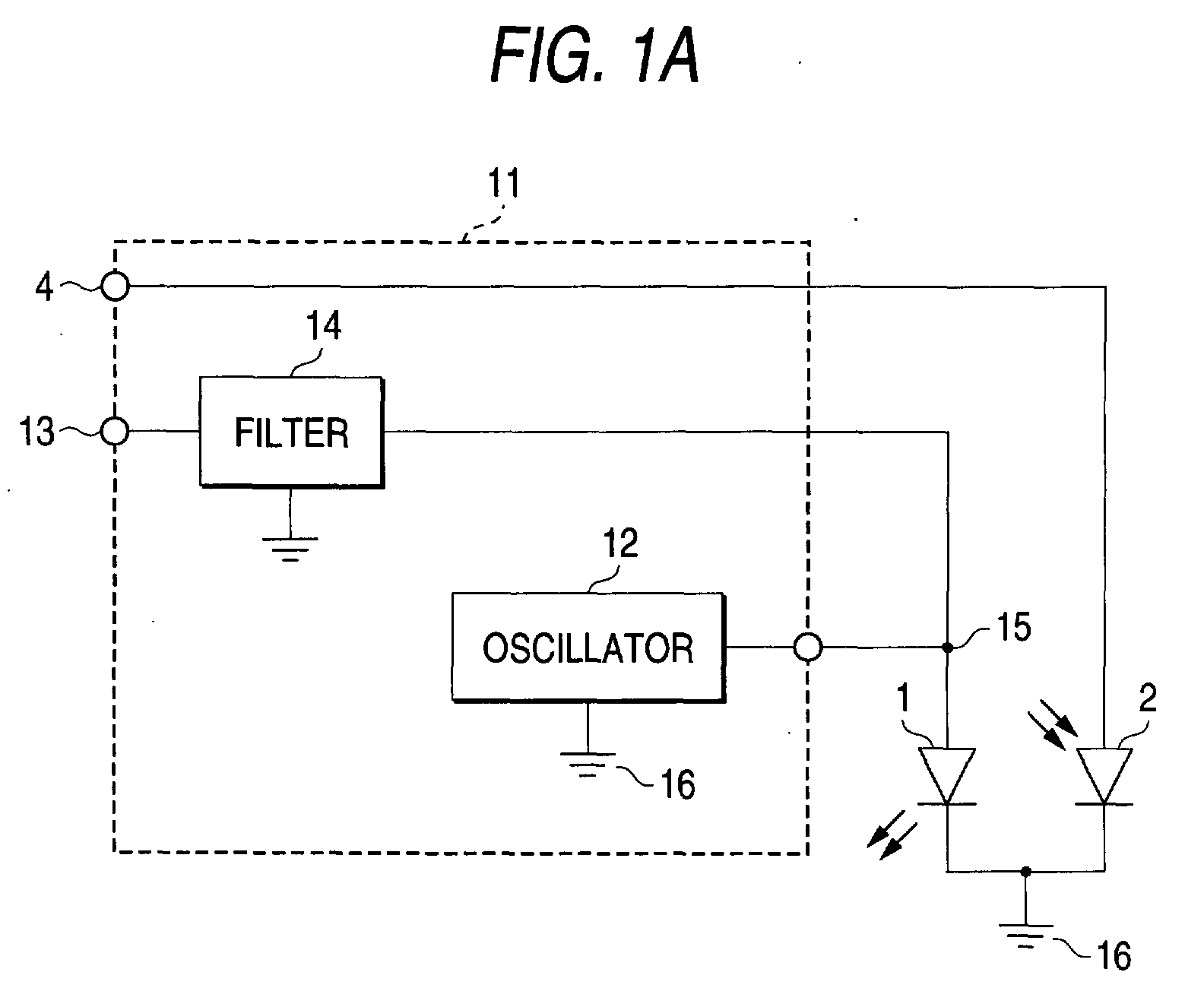
- Fig. 1A is a block diagram showing an embodiment of a high-frequency superposition module for an optical pickup according to the invention.
- Fig. 2 is a circuit diagram of Fig. 1A.
- a numeral 1 represents a laser diode for an optical pickup
- 2 a photo-detector diode
- 11 a high-frequency superposition module
- 4 a power supply terminal for the photo-detector diode
- 12 an oscillating circuit
- 13 a power supply terminal for feeding a direct current to the laser diode 1 as well as feeding power to the oscillating circuit 12
- 14 a filter for preventing a high frequency generated by the oscillating circuit 12 from being to the power supply.
- the oscillating circuit 12 is connected between a connection point 15 between the filter 14 and the laser diode 1 and a ground 16, that is, in parallel with the laser diode 1.
- the oscillating circuit 12 is composed of an active element consisting of a transistor Q1 and passive elements such as capacitors C1 through C3, inductors L1, L2, and resistors R1 through R3.
- the oscillating circuit oscillates at a high frequency of several hundreds of megahertz.
- the filter 14 is composed of an inductor L3.
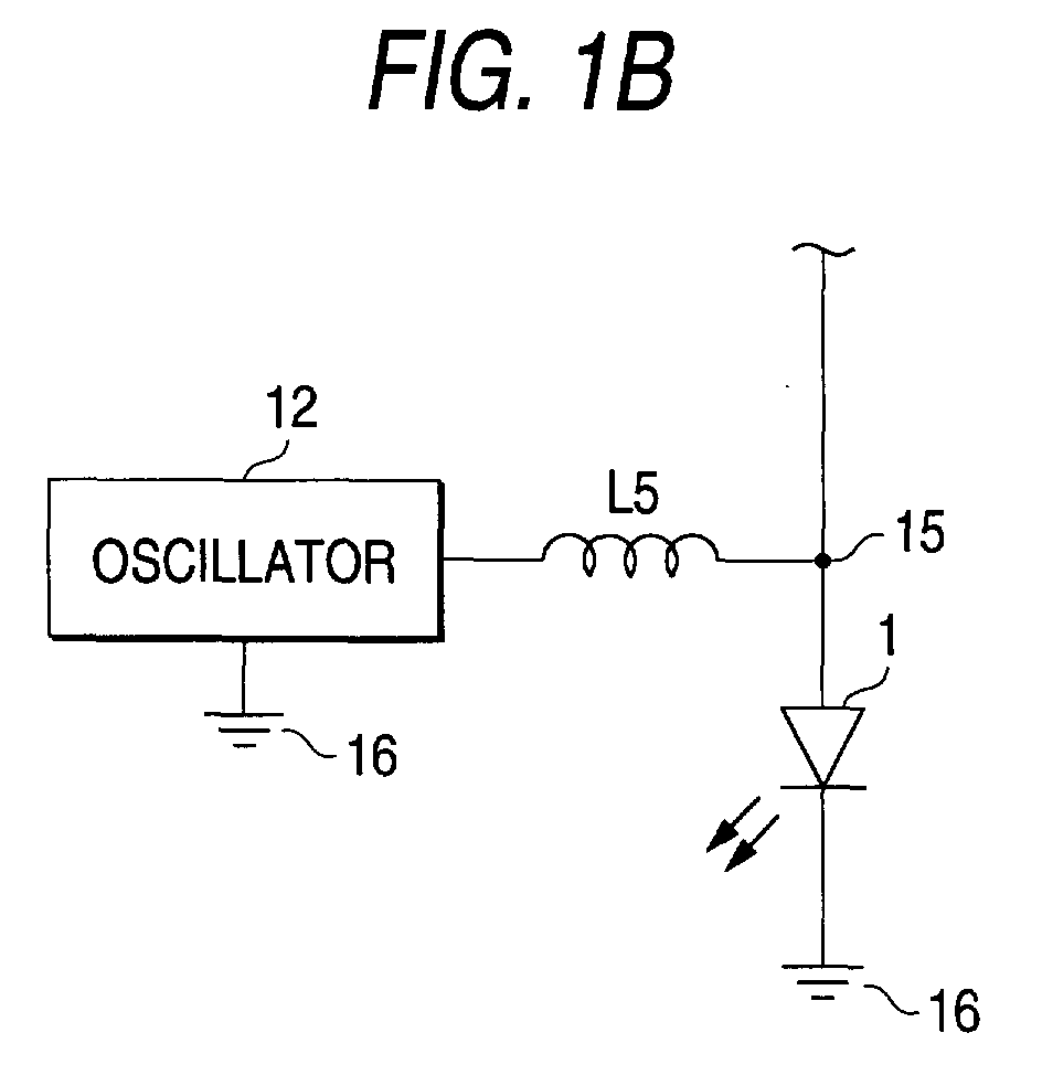
- an impedance matching circuit such as an inductor L5 and a capacitor C7 may be provided between the oscillating circuit 12 and the laser diode 1.
- the high-frequency superposition module itself can be scaled down and also power circuits for a laser diode are unified into a single circuit. This simplifies the optical pickup configuration and scales down the optical pickup.
- Fig. 3A shows a configuration of a Michelson interferomenter for measuring the visibility below. (Pmax-Pmin) / (Pmax+Pmin) where Pmax is the maximum value of optical strength, Pmin is the minimum value of optical strength.
- a high-frequency superposition module 21 under measurement composed of a related art high-frequency superposition module or a high-frequency superposition module according to the invention is connected to a power supply 20 to drive the laser diode 1.
- Laser beams generated by the laser diode 1 are made into parallel rays by using a collimator lens.
- the parallel rays are reflected on a fixed mirror 24 by way of a beam splitter 23 and transmitted to a moving mirror 25. Reflected lights from these mirrors 24, 25 are again unified into a single ray by using the beam splitter 23 and detected by a photo-detector diode 27 via a condenser lens 26.
- ⁇ 1
- a light appearing on the laser diode 1 is a complete coherent light (wavelength, phase and wave front are aligned).
- the system is operating in the multimode.
- Table 1 shows comparison of the ⁇ value between the single mode, a related art article and an article developed according to this invention, and corresponding oscillating frequency and operating power current between the related art article and the article developed according to this invention.
- Fig. 4 shows the V- ⁇ characteristic obtained when only a direct current is used to drive the laser diode 1. In this case, the ⁇ value is 98.7 % as shown in Table 1.
- Superposition amount Coherence primary peak obtained when optical output is 5 mV (%)( ⁇ value) Oscillating frequency of superposition module (MHz) Operating power current of superposition current (mA) No superposition modules 98.7 Fig. 4 Related art 66.4 Fig. 5A 372 18 Invention 59.7 Fig. 5B 361 18
- Fig. 5A shows the V- ⁇ characteristic of a related art high-frequency superposition module shown in Fig. 6 and the corresponding ⁇ value is 64.4 %.
- Fig. 5B shows the V- ⁇ characteristic of a high-frequency superposition module of the invention shown in Figs. 1A and 2 and the corresponding ⁇ value is 59.7 % from the same operating current as the related art article. showing that more efficient operation is obtained.
- a power supply dedicated to an oscillating circuit is made unnecessary.
- a dedicated power supply, a power supply terminal, and passive elements such as a filter between the power supply terminal and the oscillating circuit can be removed. This simplifies and scales down the configuration.
- the power supply for the high-frequency superposition module is also off thus generating no noise.
- the power supply for the oscillating circuit is also off thus generating no noise.
- the high-frequency superposition module itself can be scaled down and also power circuits for a laser diode are unified into a single circuit. This simplifies the optical pickup configuration and scales down the optical pickup.
Landscapes
- Physics & Mathematics (AREA)
- Optics & Photonics (AREA)
- Condensed Matter Physics & Semiconductors (AREA)
- General Physics & Mathematics (AREA)
- Electromagnetism (AREA)
- Semiconductor Lasers (AREA)
- Optical Head (AREA)
Abstract
Description
| Superposition amount Coherence primary peak obtained when optical output is 5 mV (%)(γ value) | Oscillating frequency of superposition module (MHz) | Operating power current of superposition current (mA) | |
| No superposition modules | 98.7 Fig. 4 | ||
| Related art | 66.4 Fig. 5A | 372 | 18 |
| Invention | 59.7 Fig. 5B | 361 | 18 |
Claims (3)
- A high-frequency superposition module for an optical pickup that superposes a high-frequency current on a direct current of a laser diode (1) for the optical pickup, said module comprising :an oscillating circuit (12) for feeding said high frequency to said laser diode, which includes at least an active element and passive elements; anda power supply (13) for feeding said direct current to the laser diode which is also used as a power supply for said oscillating circuit.
- A high-frequency superposition module as claimed in claim 1 further comprising an impedance matching circuit (L5; C7) being provided between the oscillating circuit and the laser diode.
- An optical pickup comprising:wherein said laser diode is driven by said high-frequency superposition module.a laser diode (1); anda high-frequency superposition module that superposes a high-frequency current on a direct current of a laser diode, said module including:an oscillating circuit (12) for feeding said high frequency to said laser diode, which includes at least an active element and passive elements; anda power supply (13) for feeding said direct current to the laser diode which is also used as a power supply for said oscillating circuit,
Applications Claiming Priority (2)
| Application Number | Priority Date | Filing Date | Title |
|---|---|---|---|
| JP2001047249 | 2001-02-22 | ||
| JP2001047249A JP2002251763A (en) | 2001-02-22 | 2001-02-22 | High frequency superimposed module for optical pickup, and optical pickup |
Publications (2)
| Publication Number | Publication Date |
|---|---|
| EP1235212A2 true EP1235212A2 (en) | 2002-08-28 |
| EP1235212A3 EP1235212A3 (en) | 2007-05-16 |
Family
ID=18908715
Family Applications (1)
| Application Number | Title | Priority Date | Filing Date |
|---|---|---|---|
| EP02290434A Withdrawn EP1235212A3 (en) | 2001-02-22 | 2002-02-22 | Optical pickup and high-frequency superposition module therefor |
Country Status (6)
| Country | Link |
|---|---|
| US (1) | US6914872B2 (en) |
| EP (1) | EP1235212A3 (en) |
| JP (1) | JP2002251763A (en) |
| KR (1) | KR20020069117A (en) |
| CN (1) | CN1224967C (en) |
| TW (1) | TWI297151B (en) |
Families Citing this family (6)
| Publication number | Priority date | Publication date | Assignee | Title |
|---|---|---|---|---|
| JP2004253444A (en) * | 2003-02-18 | 2004-09-09 | Murata Mfg Co Ltd | High frequency superposition module for driving laser diode |
| JP2005044963A (en) * | 2003-07-28 | 2005-02-17 | Tdk Corp | Laser diode module |
| US7468998B2 (en) * | 2005-03-25 | 2008-12-23 | Pavilion Integration Corporation | Radio frequency modulation of variable degree and automatic power control using external photodiode sensor for low-noise lasers of various wavelengths |
| JP5025388B2 (en) * | 2007-08-27 | 2012-09-12 | シスメックス株式会社 | Sample analyzer and sample analysis method |
| US7606273B2 (en) * | 2007-10-15 | 2009-10-20 | Pavilion Integration Corporation | Wavelength and intensity stabilized laser diode and application of same to pumping solid-state lasers |
| JP2012048801A (en) * | 2010-08-30 | 2012-03-08 | Sony Corp | Information processing unit and information processing method |
Family Cites Families (9)
| Publication number | Priority date | Publication date | Assignee | Title |
|---|---|---|---|---|
| JPS599086A (en) | 1982-07-07 | 1984-01-18 | Multi Giken Kk | Retransfer printing mode |
| US4819242A (en) * | 1985-11-20 | 1989-04-04 | Hitachi, Ltd. | Semiconductor laser driver circuit |
| JPH01133224A (en) * | 1987-04-07 | 1989-05-25 | Olympus Optical Co Ltd | Optical disk device |
| JPH0793758A (en) | 1993-09-24 | 1995-04-07 | Sony Corp | Optical pickup |
| JP2675977B2 (en) * | 1994-02-10 | 1997-11-12 | オリンパス光学工業株式会社 | Optical information recording / reproducing device |
| JPH087316A (en) * | 1994-06-21 | 1996-01-12 | Canon Inc | Optical information recording / reproducing device |
| JPH0831092A (en) * | 1994-07-20 | 1996-02-02 | Hitachi Ltd | Optical disk drive |
| JP2999684B2 (en) * | 1995-03-10 | 2000-01-17 | 株式会社日立製作所 | Optical disk recording control method and optical disk device |
| JP3620966B2 (en) * | 1998-06-30 | 2005-02-16 | 富士写真フイルム株式会社 | Semiconductor laser pumped solid state laser |
-
2001
- 2001-02-22 JP JP2001047249A patent/JP2002251763A/en active Pending
-
2002
- 2002-02-20 KR KR1020020008896A patent/KR20020069117A/en not_active Ceased
- 2002-02-21 US US10/078,371 patent/US6914872B2/en not_active Expired - Fee Related
- 2002-02-21 TW TW091102995A patent/TWI297151B/en active
- 2002-02-22 EP EP02290434A patent/EP1235212A3/en not_active Withdrawn
- 2002-02-22 CN CNB021051291A patent/CN1224967C/en not_active Expired - Fee Related
Also Published As
| Publication number | Publication date |
|---|---|
| CN1224967C (en) | 2005-10-26 |
| KR20020069117A (en) | 2002-08-29 |
| US20020163875A1 (en) | 2002-11-07 |
| US6914872B2 (en) | 2005-07-05 |
| TWI297151B (en) | 2008-05-21 |
| CN1372258A (en) | 2002-10-02 |
| EP1235212A3 (en) | 2007-05-16 |
| JP2002251763A (en) | 2002-09-06 |
Similar Documents
| Publication | Publication Date | Title |
|---|---|---|
| JP3151581B2 (en) | Lightwave rangefinder | |
| EP1744414A2 (en) | Frequency-stabilized laser and frequency stabilizing method | |
| JP2013545107A (en) | Broadband light source acousto-optic tunable filter (AOTF) for fluorescence measurement system | |
| US6914872B2 (en) | Optical pickup and high-frequency superposition module therefor | |
| US5471490A (en) | Device in which electromagnetic radiation is raised in frequency and apparatus for optically scanning an information plane, comprising such a device | |
| US20010019563A1 (en) | Light wavelength conversion module | |
| US5781222A (en) | Optical information recording/reproducing apparatus supplying a smaller high-frequency current to a first semiconductor laser for generating a light beam to record information than to a second semiconductor laser for reproducing recorded information | |
| US5025449A (en) | Optical pumping-type solid-state laser apparatus with a semiconductor laser device | |
| JP2000505599A (en) | Method and apparatus for using laser diode | |
| US20090141748A1 (en) | Tunable laser light source and controlling method of the same | |
| KR20130023187A (en) | Optical coherence tomography using active mode-locking fiber laser | |
| CN102812602B (en) | Laser with tunable outer cavity and method for using same | |
| EP0206338A2 (en) | Light modulator | |
| US7313073B2 (en) | Optical pickup and optical disk system | |
| US6891875B2 (en) | Optical disc device | |
| JPH0637384A (en) | Light frequency stabilizing light source apparatus | |
| JP3111333B2 (en) | Light source means | |
| US5081710A (en) | Laser transmitter | |
| JP3786348B2 (en) | High frequency superposition module for optical pickup | |
| JP2888224B2 (en) | Laser diode drive | |
| JPH0466059B2 (en) | ||
| JP3018418B2 (en) | Optical loss measuring device | |
| JPH04321943A (en) | Optical information recording/reproducing device | |
| CN117791273A (en) | Ultra-narrow linewidth sweep frequency laser | |
| JPS63276720A (en) | optical disk device |
Legal Events
| Date | Code | Title | Description |
|---|---|---|---|
| PUAI | Public reference made under article 153(3) epc to a published international application that has entered the european phase |
Free format text: ORIGINAL CODE: 0009012 |
|
| AK | Designated contracting states |
Kind code of ref document: A2 Designated state(s): AT BE CH CY DE DK ES FI FR GB GR IE IT LI LU MC NL PT SE TR |
|
| AX | Request for extension of the european patent |
Free format text: AL;LT;LV;MK;RO;SI |
|
| PUAL | Search report despatched |
Free format text: ORIGINAL CODE: 0009013 |
|
| AK | Designated contracting states |
Kind code of ref document: A3 Designated state(s): AT BE CH CY DE DK ES FI FR GB GR IE IT LI LU MC NL PT SE TR |
|
| AX | Request for extension of the european patent |
Extension state: AL LT LV MK RO SI |
|
| AKX | Designation fees paid | ||
| REG | Reference to a national code |
Ref country code: DE Ref legal event code: 8566 |
|
| STAA | Information on the status of an ep patent application or granted ep patent |
Free format text: STATUS: THE APPLICATION IS DEEMED TO BE WITHDRAWN |
|
| 18D | Application deemed to be withdrawn |
Effective date: 20071117 |