EP1235194A2 - Fernsteuer- und Überwachungssystem für Geräte mit Sensoren und/oder Aktuatoren - Google Patents
Fernsteuer- und Überwachungssystem für Geräte mit Sensoren und/oder Aktuatoren Download PDFInfo
- Publication number
- EP1235194A2 EP1235194A2 EP02002674A EP02002674A EP1235194A2 EP 1235194 A2 EP1235194 A2 EP 1235194A2 EP 02002674 A EP02002674 A EP 02002674A EP 02002674 A EP02002674 A EP 02002674A EP 1235194 A2 EP1235194 A2 EP 1235194A2
- Authority
- EP
- European Patent Office
- Prior art keywords
- actuators
- sensors
- communication device
- downstream
- machine
- Prior art date
- Legal status (The legal status is an assumption and is not a legal conclusion. Google has not performed a legal analysis and makes no representation as to the accuracy of the status listed.)
- Withdrawn
Links
Images
Classifications
-
- G—PHYSICS
- G08—SIGNALLING
- G08C—TRANSMISSION SYSTEMS FOR MEASURED VALUES, CONTROL OR SIMILAR SIGNALS
- G08C17/00—Arrangements for transmitting signals characterised by the use of a wireless electrical link
- G08C17/02—Arrangements for transmitting signals characterised by the use of a wireless electrical link using a radio link
-
- B—PERFORMING OPERATIONS; TRANSPORTING
- B25—HAND TOOLS; PORTABLE POWER-DRIVEN TOOLS; MANIPULATORS
- B25J—MANIPULATORS; CHAMBERS PROVIDED WITH MANIPULATION DEVICES
- B25J19/00—Accessories fitted to manipulators, e.g. for monitoring, for viewing; Safety devices combined with or specially adapted for use in connection with manipulators
- B25J19/02—Sensing devices
- B25J19/027—Electromagnetic sensing devices
Definitions
- the invention relates to a system for a plurality of sensors and / or Machine or system with actuators.
- the invention has for its object a system for a variety of sensors and / or to specify a machine or system which has actuators and which is suitable for certain Types of machines or systems, especially robots, is optimized at which the sensors and / or actuators are clustered and relatively closely packed on certain Places.
- the advantages that can be achieved with the invention are in particular that the proposed System for example with robot arms with heaped up in certain places occurring sensors and / or actuators is cheaper and also less Weight than that in documents DE 199 26 799 A1 and DE 199 26 562 proposed solutions in which a separate communication facility in each individual sensor and / or each individual actuator is realized.
- the proposed system is also less expensive and has less weight off if you compare it to a conventional system with wired sensors and / or compares actuators.
- the proposed system leads to advantageously reduced weight Robot arms, which is beneficial in terms of the dynamics of the arms and the drive power required for the movements of the robot arms.
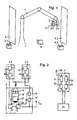
- Fig. 1 is an arrangement with a robot arm and a plurality of sensors and / or actuators. It is a robotic arm 1 that can be bent several times to recognize, wherein at the end joint portion of the robot arm a group of relatively closely adjacent sensors / actuators 2.1, 2.2 ... 2.n is installed. It is below Always talk about sensors / actuators, which are either sensors or can be actuators.
- the sensors / actuators 2.1, 2.2 ... 2.n are short Connection cable connected to a common communication device 3, which is also installed on the end joint section of the robot arm.
- the communication device 3 contains the required radio transmitters and / or Radio receiver for such wireless communication with a central base station 4 to realize. Details on this are described in FIG. 2.
- the electrical energy supply to the sensors / actuators 2.1... 2.n is preferably carried out also using the common communication facility.
- For wireless electrical supply are two primary windings 5.1 and 5.2 on both sides of the robot installed and each connected to a magnetic field generating device 6.1 or 6.2.
- These magnetic field generating devices 6.1, 6.2 have an oscillator on which the primary windings 5.1, 5.2 with a medium-frequency vibration in Ranges from about 15 kHz to about 15 MHz, with the primary windings preferably a resonance capacitor is in parallel or in series. In particular between A medium-frequency magnetic field is formed in the primary windings 5.1, 5.2.
- the communication device 3 contains at least one secondary winding. Due to the purely magnetic coupling between primary winding 5.1, 5.2 and secondary winding a conversion takes place in the sense of a medium-frequency transformer from magnetic energy to electrical energy by means of this secondary winding.
- the 2 shows the structure of sensors / actuators, a common communication device and base station shown in detail.
- a communication device 3 with sensor 2.1 and actuator 2.2 connected to it.
- the connections are made each via short connecting lines.
- other sensors can and / or actuators connected to this common communication device 3 his.
- the sensor 2.1 has a sensor that detects the sensor environment Sensor head 7 with downstream signal evaluation 8.
- the processed sensor signal arrives at a modulator / encoder 11 with a radio transmitter 12 connected downstream and antenna 13.
- the actuator 2.2 has an actuator unit 9, for example a compressed air valve or Contactor, and a control unit 10 for this.
- the control unit 10 is connected to one Demodulator / decoder 15 of the communication device 3 connected.
- the Demodulator / decoder 15 is preceded by a radio receiver 14 which is connected to the Antenna 13 is connected.
- the communication device 3 expediently an electrical power supply unit, which is used to supply the components the connected sensors and / or actuators as well as for feeding the components the communication device 3 itself serves.
- This power supply unit consists of at least one secondary winding 16, one in parallel or resonator capacitor 17 arranged in series, a rectifier 18 and a Energy storage 19 at the DC output of the rectifier.
- the one that can be seen in the rectifier 18 Voltage becomes the sensor head 7, the signal evaluation 8, if necessary the actuator unit 8, the control unit 10 and the modulator / encoder 11, the Radio transmitter 12, the radio receiver 14 and the demodulator / decoder 15 supplied.
- actuator units can also be used, which - except the control - not operated electrically, but for example by compressed air.
- secondary winding configurations can also be used, for example three secondary windings arranged orthogonally to one another.
- the to a central computer 23 (process computer, programmable logic controller) connected base station 4 has an antenna 20 to which a radio receiver 21 and a radio transmitter 25 are connected.
- the signals of the radio receiver 21 are fed to a demodulator / decoder 22 which is connected to the central computer 23 is connected.
- a modulator / encoder 24 is connected upstream of the radio transmitter 25, which is also connected to the central computer 23.
Landscapes
- Engineering & Computer Science (AREA)
- Physics & Mathematics (AREA)
- Electromagnetism (AREA)
- Robotics (AREA)
- Mechanical Engineering (AREA)
- Computer Networks & Wireless Communication (AREA)
- General Physics & Mathematics (AREA)
- Selective Calling Equipment (AREA)
Abstract
- wobei an der Maschine oder Anlage mindestens eine Kommunikationseinrichtung (3) montiert ist, an welche über kurze Verbindungskabel mindestens zwei Sensoren und/oder Aktoren (2.1...2.n) angeschlossen sind,
- wobei die Kommunikationseinrichtung (3) einen Modulator/Codierer (11) mit nachgeschaltetem Funksender (12) zum Senden von Sensorsignalen und/oder einen Funkempfänger (14) mit nachgeschaltetem Demodulator /Decodierer (15) zum Empfang von Aktor-Ansteuersignalen aufweist,
- wobei die Kommunikationseinrichtung (3) über Funksignale mit einer Basisstation (4) kommuniziert, welche mit einem Zentralrechner der Maschine oder Anlage (1) verbunden ist und
- wobei die Basisstation (4) einen Funkempfänger (21) mit nachgeschaltetem Demodulator/Decodierer (22) zum Empfang von Sensorsignalen und/oder einen Modulator/Codierer (24) mit nachgeschaltetem Funksender (25) zum Senden von Aktor-Ansteuersignalen aufweist.
Description
- wobei jeder Näherungssensor mindestens eine zur Energieaufnahme aus einem mittelfrequenten Magnetfeld geeignete Sekundärwicklung aufweist,
- wobei mindestens eine von einem mittelfrequenten Oszillator gespeiste Primärwicklung zur drahtlosen Versorgung der Näherungssensoren mit elektrischer Energie vorgesehen ist und
- wobei jeder Näherungssensor mit einer Sendeeinrichtung ausgestattet ist, welche interessierende Sensor-Informationen beinhaltende Funksignale an eine zentrale, mit einem Prozeßrechner der Maschine verbundene Empfangseinrichtung abgibt.
- wobei jeder Aktor mindestens eine zur Energieaufnahme aus einem mittelfrequenten Magnetfeld geeignete Sekundärwicklung aufweist,
- wobei mindestens eine von einem mittelfrequenten Oszillator gespeiste Primärwicklung zur drahtlosen Versorgung der Aktoren mit elektrischer Energie vorgesehen ist und
- wobei jeder Aktor mit einer Empfangseinrichtung ausgestattet ist, welche Funksignale einer mit einem Prozeßrechner der Maschine verbundenen zentralen Sendeeinrichtung empfängt.
- wobei an der Maschine oder Anlage mindestens eine Kommunikationseinrichtung montiert ist, an welche über kurze Verbindungskabel mindestens zwei Sensoren und/oder Aktoren angeschlossen sind,
- wobei die Kommunikationseinrichtung einen Modulator/Codierer mit nachgeschaltetem Funksender zum Senden von Sensorsignalen und/oder einen Funkempfänger mit nachgeschaltetem Demodulator /Decodierer zum Empfang von Aktor-Ansteuersignalen aufweist,
- wobei die Kommunikationseinrichtung über Funksignale mit einer Basisstation kommuniziert, welche mit einem Zentralrechner der Maschine oder Anlage verbunden ist und
- wobei die Basisstation einen Funkempfänger mit nachgeschaltetem Demodulator/Decodierer zum Empfang von Sensorsignalen und/oder einen Modulator/Codierer mit nachgeschaltetem Funksender zum Senden von Aktor-Ansteuersignalen aufweist.
- Fig.1
- eine Anordnung mit einem Roboterarm und einer Vielzahl von Sensoren/Aktoren,
- Fig. 2
- den Aufbau von Sensoren/Aktoren, gemeinsamer Kommunikationseinrichtung und Basisstation im Detail.
Claims (3)
- System für eine eine Vielzahl von Sensoren und/oder Aktoren (2.1 ...2.n) aufweisende Maschine oder Anlage (1),wobei an der Maschine oder Anlage mindestens eine Kommunikationseinrichtung (3) montiert ist, an welche über kurze Verbindungskabel mindestens zwei Sensoren und/oder Aktoren (2.1...2.n) angeschlossen sind,wobei die Kommunikationseinrichtung (3) einen Modulator/Codierer (11) mit nachgeschaltetem Funksender (12) zum Senden von Sensorsignalen und/oder einen Funkempfänger (14) mit nachgeschaltetem Demodulator /Decodierer (15) zum Empfang von Aktor-Ansteuersignalen aufweist,wobei die Kommunikationseinrichtung (3) über Funksignale mit einer Basisstation (4) kommuniziert, welche mit einem Zentralrechner der Maschine oder Anlage (1) verbunden ist undwobei die Basisstation (4) einen Funkempfänger (21) mit nachgeschaltetem Demodulator/Decodierer (22) zum Empfang von Sensorsignalen und/oder einen Modulator/Codierer (24) mit nachgeschaltetem Funksender (25) zum Senden von Aktor-Ansteuersignalen aufweist.
- System nach Anspruch 1, dadurch gekennzeichnet, daß die Kommunikationseinrichtung (3) zusätzlich zur elektrischen Energieversorgung der Sensoren und/oder Aktoren (2.1...2.n) dient, wozu die Maschine oder Anlage (1) im Einflußbereich mindestens einer von einer Magnetfelderzeugungsvorrichtung (6.1, 6.2) gespeisten, ein Magnetfeld erzeugenden Primärwicklung (5.2, 5.2) liegt und wozu die Kommunikationseinrichtung (3) mindestens eine zur Energieaufnahme aus diesem Magnetfeld geeignete Sekundärwicklung (16) mit nachgeschaltetem Gleichrichter (18) aufweist.
- System nach Anspruch 2, dadurch gekennzeichnet, daß zur Bildung von Resonanzkreisen jeweils mindesten ein Resonanzkondensator in Reihe oder parallel zur Primärwicklung (5.1, 5.2) und/oder Sekundärwicklung (16) angeordnet ist.
Applications Claiming Priority (2)
| Application Number | Priority Date | Filing Date | Title |
|---|---|---|---|
| DE10108243A DE10108243A1 (de) | 2001-02-21 | 2001-02-21 | System für eine Vielzahl von Sensoren und/oder Aktoren aufweisende Maschine oder Anlage |
| DE10108243 | 2001-02-21 |
Publications (2)
| Publication Number | Publication Date |
|---|---|
| EP1235194A2 true EP1235194A2 (de) | 2002-08-28 |
| EP1235194A3 EP1235194A3 (de) | 2008-01-23 |
Family
ID=7674935
Family Applications (1)
| Application Number | Title | Priority Date | Filing Date |
|---|---|---|---|
| EP02002674A Withdrawn EP1235194A3 (de) | 2001-02-21 | 2002-02-06 | Fernsteuer- und Überwachungssystem für Geräte mit Sensoren und/oder Aktuatoren |
Country Status (3)
| Country | Link |
|---|---|
| US (1) | US20020118098A1 (de) |
| EP (1) | EP1235194A3 (de) |
| DE (1) | DE10108243A1 (de) |
Families Citing this family (8)
| Publication number | Priority date | Publication date | Assignee | Title |
|---|---|---|---|---|
| DE10304585A1 (de) * | 2003-02-05 | 2004-08-19 | Abb Research Ltd. | Zwei- oder mehrdimensionale Magnetfelderzeugungsanordnung |
| SE527946C2 (sv) * | 2003-12-10 | 2006-07-18 | Abb Ab | Kraftförsörjning för robottillämpningar |
| SE0303445L (sv) * | 2003-12-17 | 2005-06-18 | Abb Research Ltd | Verktyg för en industrirobot |
| DE102005032647A1 (de) * | 2005-07-13 | 2007-02-08 | Abb Patent Gmbh | Baukastensystem zur Energieversorgung eines drahtlosen I/O-Gerätes, an welches ein oder mehrere Knoten angschlossen sind |
| US7654348B2 (en) | 2006-10-06 | 2010-02-02 | Irobot Corporation | Maneuvering robotic vehicles having a positionable sensor head |
| US9522595B2 (en) | 2011-01-27 | 2016-12-20 | Irobot Defense Holdings, Inc. | Small unmanned ground vehicle |
| US9346499B2 (en) | 2011-01-27 | 2016-05-24 | Irobot Corporation | Resilient wheel assemblies |
| EP3800014A1 (de) * | 2019-10-01 | 2021-04-07 | SMW-AUTOBLOK Spannsysteme GmbH | Roboter zum greifen und/oder halten von gegenständen |
Family Cites Families (11)
| Publication number | Priority date | Publication date | Assignee | Title |
|---|---|---|---|---|
| US4827395A (en) * | 1983-04-21 | 1989-05-02 | Intelli-Tech Corporation | Manufacturing monitoring and control systems |
| US4912471A (en) * | 1983-11-03 | 1990-03-27 | Mitron Systems Corporation | Interrogator-responder communication system |
| US5153583A (en) * | 1987-11-18 | 1992-10-06 | Uniscan Ltd. | Transponder |
| DE4344071A1 (de) * | 1993-12-23 | 1995-07-06 | Josef Femboeck | Vorrichtung zur Übertragung von Energie und/oder Daten |
| US5745049A (en) * | 1995-07-20 | 1998-04-28 | Yokogawa Electric Corporation | Wireless equipment diagnosis system |
| US5714946A (en) * | 1996-04-26 | 1998-02-03 | Caterpillar Inc. | Apparatus for communicating with a machine when the machine ignition is turned off |
| DE19826513A1 (de) * | 1998-06-15 | 1999-12-23 | Siemens Ag | Automatisierungssystem mit Funksensor |
| EP0989525A3 (de) * | 1998-08-31 | 2001-09-19 | Kabushiki Kaisha Kobe Seiko Sho | Verwaltungssystem für Baumaschinen |
| US6806808B1 (en) * | 1999-02-26 | 2004-10-19 | Sri International | Wireless event-recording device with identification codes |
| DE50015873D1 (de) * | 1999-06-11 | 2010-04-08 | Abb Research Ltd | System für eine eine vielzahl von aktoren aufweisende maschine |
| US6181026B1 (en) * | 1999-06-28 | 2001-01-30 | Ford Global Technologies, Inc. | Vehicle immobilizer system for electronic engine control |
-
2001
- 2001-02-21 DE DE10108243A patent/DE10108243A1/de not_active Withdrawn
-
2002
- 2002-02-06 EP EP02002674A patent/EP1235194A3/de not_active Withdrawn
- 2002-02-21 US US10/080,361 patent/US20020118098A1/en not_active Abandoned
Also Published As
| Publication number | Publication date |
|---|---|
| US20020118098A1 (en) | 2002-08-29 |
| EP1235194A3 (de) | 2008-01-23 |
| DE10108243A1 (de) | 2002-08-22 |
Similar Documents
| Publication | Publication Date | Title |
|---|---|---|
| EP1190476B1 (de) | System für eine eine vielzahl von aktoren aufweisende maschine | |
| DE10216422C5 (de) | Vorrichtung zur induktiven Energieversorgung und Führung eines beweglichen Objektes | |
| EP3319748B1 (de) | Vorrichtung zur erzeugung einer ultraschallschwingung eines werkzeugs und zur messung von schwingungsparametern | |
| DE10304584A1 (de) | Anordnung zur drahtlosen Versorgung eines Systems mit einer Vielzahl Sensoren und/oder Aktoren mit elektrischer Energie | |
| CH661994A5 (de) | Verfahren zur uebertragung von informationen und befehlen von einer bodenstelle auf ein schienenfahrzeug. | |
| EP1294074A2 (de) | Magnetfelderzeugungssystem und Anordnung zur drahtlosen Versorgung einer Vielzahl Sensoren und/oder Aktoren | |
| EP2803143B1 (de) | Induktive energieversorgungseinrichtung | |
| DE19640367A1 (de) | Leitungslose Energie- und Datenübertragung für ein modulares Peripherie-System | |
| DE10335035A1 (de) | System und Verfahren zur Identifizierung von Automatisierungskomponenten | |
| EP1235194A2 (de) | Fernsteuer- und Überwachungssystem für Geräte mit Sensoren und/oder Aktuatoren | |
| EP3279027B1 (de) | Anordnung mit einer netzwerkvorrichtung, die zur befestigung an einem fahrdraht einer stromdurchflossenen oberleitung ausgebildet ist | |
| DE10041160A1 (de) | Containerstation | |
| EP1532599B1 (de) | Verfahren zum betrieb eines systems mit einer vielzahl knoten und einer basisstation,gemäss tdma und system hierzu | |
| DE102018130342A1 (de) | Schaltgeräteanordnung | |
| EP1243990B1 (de) | Leit/Steuersystem mit einer speicherprogrammierbaren Steuerung und einer Vielzahl von Aktoren und/oder Sensoren und/oder Eingabeeinheiten und/oder Ausgabeeinheiten und/oder Ein/Ausgabeeinheiten | |
| DE19918655A1 (de) | Einrichtung zum Betrieb ausgewählter elektrischer Verbraucher auf Bahnfahrzeugen | |
| EP2091799B1 (de) | Vorrichtung zur kontaktlosen ermittlung des energiebedarfs eines weichenstellantriebs | |
| DE10321842B3 (de) | Verfahren und Vorrichtung zum Betrieb eines Sensors oder Aktors | |
| DE10347584B4 (de) | System mit einer Vielzahl drahtlos gespeister Sensoren und/oder Aktoren und einer mit einem Automatisierungsgerät verbundenen Basisstation | |
| EP3541680B1 (de) | Verfahren und eisenbahnkomponente zum übertragen von nachrichten | |
| DE10304587A1 (de) | Magnetfelderzeugungssystem mit einer mindestens zweidimensionalen Wicklungsanordnung | |
| EP1744474B1 (de) | Basisstation eines gemäss TDMA (Time Division Multiple Access) betriebenen Kommunikationssystems | |
| DE3446253C2 (de) | ||
| DE19944896A1 (de) | Verfahren zur Ortung von Schienenfahrzeugen | |
| DE102023136529A1 (de) | Sensorvorrichtung, abnormalitätsdiagnosesystem und roboter |
Legal Events
| Date | Code | Title | Description |
|---|---|---|---|
| PUAI | Public reference made under article 153(3) epc to a published international application that has entered the european phase |
Free format text: ORIGINAL CODE: 0009012 |
|
| AK | Designated contracting states |
Kind code of ref document: A2 Designated state(s): AT BE CH CY DE DK ES FI FR GB GR IE IT LI LU MC NL PT SE TR |
|
| AX | Request for extension of the european patent |
Free format text: AL;LT;LV;MK;RO;SI |
|
| PUAL | Search report despatched |
Free format text: ORIGINAL CODE: 0009013 |
|
| AK | Designated contracting states |
Kind code of ref document: A3 Designated state(s): AT BE CH CY DE DK ES FI FR GB GR IE IT LI LU MC NL PT SE TR |
|
| AX | Request for extension of the european patent |
Extension state: AL LT LV MK RO SI |
|
| AKX | Designation fees paid |
Designated state(s): DE FR IT |
|
| STAA | Information on the status of an ep patent application or granted ep patent |
Free format text: STATUS: THE APPLICATION IS DEEMED TO BE WITHDRAWN |
|
| 18D | Application deemed to be withdrawn |
Effective date: 20080724 |