EP1235098A2 - LCD module and a combination switch using the same - Google Patents
LCD module and a combination switch using the same Download PDFInfo
- Publication number
- EP1235098A2 EP1235098A2 EP02004144A EP02004144A EP1235098A2 EP 1235098 A2 EP1235098 A2 EP 1235098A2 EP 02004144 A EP02004144 A EP 02004144A EP 02004144 A EP02004144 A EP 02004144A EP 1235098 A2 EP1235098 A2 EP 1235098A2
- Authority
- EP
- European Patent Office
- Prior art keywords
- lcd module
- front panel
- panel
- transparent front
- rear panel
- Prior art date
- Legal status (The legal status is an assumption and is not a legal conclusion. Google has not performed a legal analysis and makes no representation as to the accuracy of the status listed.)
- Withdrawn
Links
Images





Classifications
-
- G—PHYSICS
- G02—OPTICS
- G02F—OPTICAL DEVICES OR ARRANGEMENTS FOR THE CONTROL OF LIGHT BY MODIFICATION OF THE OPTICAL PROPERTIES OF THE MEDIA OF THE ELEMENTS INVOLVED THEREIN; NON-LINEAR OPTICS; FREQUENCY-CHANGING OF LIGHT; OPTICAL LOGIC ELEMENTS; OPTICAL ANALOGUE/DIGITAL CONVERTERS
- G02F1/00—Devices or arrangements for the control of the intensity, colour, phase, polarisation or direction of light arriving from an independent light source, e.g. switching, gating or modulating; Non-linear optics
- G02F1/01—Devices or arrangements for the control of the intensity, colour, phase, polarisation or direction of light arriving from an independent light source, e.g. switching, gating or modulating; Non-linear optics for the control of the intensity, phase, polarisation or colour
- G02F1/13—Devices or arrangements for the control of the intensity, colour, phase, polarisation or direction of light arriving from an independent light source, e.g. switching, gating or modulating; Non-linear optics for the control of the intensity, phase, polarisation or colour based on liquid crystals, e.g. single liquid crystal display cells
- G02F1/133—Constructional arrangements; Operation of liquid crystal cells; Circuit arrangements
- G02F1/1333—Constructional arrangements; Manufacturing methods
-
- G—PHYSICS
- G02—OPTICS
- G02F—OPTICAL DEVICES OR ARRANGEMENTS FOR THE CONTROL OF LIGHT BY MODIFICATION OF THE OPTICAL PROPERTIES OF THE MEDIA OF THE ELEMENTS INVOLVED THEREIN; NON-LINEAR OPTICS; FREQUENCY-CHANGING OF LIGHT; OPTICAL LOGIC ELEMENTS; OPTICAL ANALOGUE/DIGITAL CONVERTERS
- G02F1/00—Devices or arrangements for the control of the intensity, colour, phase, polarisation or direction of light arriving from an independent light source, e.g. switching, gating or modulating; Non-linear optics
- G02F1/01—Devices or arrangements for the control of the intensity, colour, phase, polarisation or direction of light arriving from an independent light source, e.g. switching, gating or modulating; Non-linear optics for the control of the intensity, phase, polarisation or colour
- G02F1/13—Devices or arrangements for the control of the intensity, colour, phase, polarisation or direction of light arriving from an independent light source, e.g. switching, gating or modulating; Non-linear optics for the control of the intensity, phase, polarisation or colour based on liquid crystals, e.g. single liquid crystal display cells
- G02F1/133—Constructional arrangements; Operation of liquid crystal cells; Circuit arrangements
- G02F1/1333—Constructional arrangements; Manufacturing methods
- G02F1/133308—Support structures for LCD panels, e.g. frames or bezels
-
- G—PHYSICS
- G06—COMPUTING OR CALCULATING; COUNTING
- G06F—ELECTRIC DIGITAL DATA PROCESSING
- G06F3/00—Input arrangements for transferring data to be processed into a form capable of being handled by the computer; Output arrangements for transferring data from processing unit to output unit, e.g. interface arrangements
- G06F3/01—Input arrangements or combined input and output arrangements for interaction between user and computer
- G06F3/02—Input arrangements using manually operated switches, e.g. using keyboards or dials
- G06F3/023—Arrangements for converting discrete items of information into a coded form, e.g. arrangements for interpreting keyboard generated codes as alphanumeric codes, operand codes or instruction codes
- G06F3/0238—Programmable keyboards
-
- H—ELECTRICITY
- H01—ELECTRIC ELEMENTS
- H01H—ELECTRIC SWITCHES; RELAYS; SELECTORS; EMERGENCY PROTECTIVE DEVICES
- H01H9/00—Details of switching devices, not covered by groups H01H1/00 - H01H7/00
- H01H9/18—Distinguishing marks on switches, e.g. for indicating switch location in the dark; Adaptation of switches to receive distinguishing marks
- H01H9/181—Distinguishing marks on switches, e.g. for indicating switch location in the dark; Adaptation of switches to receive distinguishing marks using a programmable display, e.g. LED or LCD
-
- G—PHYSICS
- G02—OPTICS
- G02F—OPTICAL DEVICES OR ARRANGEMENTS FOR THE CONTROL OF LIGHT BY MODIFICATION OF THE OPTICAL PROPERTIES OF THE MEDIA OF THE ELEMENTS INVOLVED THEREIN; NON-LINEAR OPTICS; FREQUENCY-CHANGING OF LIGHT; OPTICAL LOGIC ELEMENTS; OPTICAL ANALOGUE/DIGITAL CONVERTERS
- G02F1/00—Devices or arrangements for the control of the intensity, colour, phase, polarisation or direction of light arriving from an independent light source, e.g. switching, gating or modulating; Non-linear optics
- G02F1/01—Devices or arrangements for the control of the intensity, colour, phase, polarisation or direction of light arriving from an independent light source, e.g. switching, gating or modulating; Non-linear optics for the control of the intensity, phase, polarisation or colour
- G02F1/13—Devices or arrangements for the control of the intensity, colour, phase, polarisation or direction of light arriving from an independent light source, e.g. switching, gating or modulating; Non-linear optics for the control of the intensity, phase, polarisation or colour based on liquid crystals, e.g. single liquid crystal display cells
- G02F1/133—Constructional arrangements; Operation of liquid crystal cells; Circuit arrangements
- G02F1/1333—Constructional arrangements; Manufacturing methods
- G02F1/133302—Rigid substrates, e.g. inorganic substrates
-
- G—PHYSICS
- G02—OPTICS
- G02F—OPTICAL DEVICES OR ARRANGEMENTS FOR THE CONTROL OF LIGHT BY MODIFICATION OF THE OPTICAL PROPERTIES OF THE MEDIA OF THE ELEMENTS INVOLVED THEREIN; NON-LINEAR OPTICS; FREQUENCY-CHANGING OF LIGHT; OPTICAL LOGIC ELEMENTS; OPTICAL ANALOGUE/DIGITAL CONVERTERS
- G02F1/00—Devices or arrangements for the control of the intensity, colour, phase, polarisation or direction of light arriving from an independent light source, e.g. switching, gating or modulating; Non-linear optics
- G02F1/01—Devices or arrangements for the control of the intensity, colour, phase, polarisation or direction of light arriving from an independent light source, e.g. switching, gating or modulating; Non-linear optics for the control of the intensity, phase, polarisation or colour
- G02F1/13—Devices or arrangements for the control of the intensity, colour, phase, polarisation or direction of light arriving from an independent light source, e.g. switching, gating or modulating; Non-linear optics for the control of the intensity, phase, polarisation or colour based on liquid crystals, e.g. single liquid crystal display cells
- G02F1/133—Constructional arrangements; Operation of liquid crystal cells; Circuit arrangements
- G02F1/1333—Constructional arrangements; Manufacturing methods
- G02F1/133368—Cells having two substrates with different characteristics, e.g. different thickness or material
-
- G—PHYSICS
- G02—OPTICS
- G02F—OPTICAL DEVICES OR ARRANGEMENTS FOR THE CONTROL OF LIGHT BY MODIFICATION OF THE OPTICAL PROPERTIES OF THE MEDIA OF THE ELEMENTS INVOLVED THEREIN; NON-LINEAR OPTICS; FREQUENCY-CHANGING OF LIGHT; OPTICAL LOGIC ELEMENTS; OPTICAL ANALOGUE/DIGITAL CONVERTERS
- G02F2201/00—Constructional arrangements not provided for in groups G02F1/00 - G02F7/00
- G02F2201/50—Protective arrangements
- G02F2201/503—Arrangements improving the resistance to shock
-
- H—ELECTRICITY
- H01—ELECTRIC ELEMENTS
- H01H—ELECTRIC SWITCHES; RELAYS; SELECTORS; EMERGENCY PROTECTIVE DEVICES
- H01H13/00—Switches having rectilinearly-movable operating part or parts adapted for pushing or pulling in one direction only, e.g. push-button switch
- H01H13/02—Details
- H01H13/12—Movable parts; Contacts mounted thereon
- H01H13/14—Operating parts, e.g. push-button
-
- H—ELECTRICITY
- H01—ELECTRIC ELEMENTS
- H01H—ELECTRIC SWITCHES; RELAYS; SELECTORS; EMERGENCY PROTECTIVE DEVICES
- H01H15/00—Switches having rectilinearly-movable operating part or parts adapted for actuation in opposite directions, e.g. slide switch
- H01H15/02—Details
- H01H15/06—Movable parts; Contacts mounted thereon
- H01H15/10—Operating parts
-
- H—ELECTRICITY
- H01—ELECTRIC ELEMENTS
- H01H—ELECTRIC SWITCHES; RELAYS; SELECTORS; EMERGENCY PROTECTIVE DEVICES
- H01H2219/00—Legends
- H01H2219/002—Legends replaceable; adaptable
- H01H2219/01—Liquid crystal
-
- H—ELECTRICITY
- H01—ELECTRIC ELEMENTS
- H01H—ELECTRIC SWITCHES; RELAYS; SELECTORS; EMERGENCY PROTECTIVE DEVICES
- H01H2219/00—Legends
- H01H2219/036—Light emitting elements
- H01H2219/037—Light emitting elements using organic materials, e.g. organic LED
-
- H—ELECTRICITY
- H01—ELECTRIC ELEMENTS
- H01H—ELECTRIC SWITCHES; RELAYS; SELECTORS; EMERGENCY PROTECTIVE DEVICES
- H01H23/00—Tumbler or rocker switches, i.e. switches characterised by being operated by rocking an operating member in the form of a rocker button
- H01H23/02—Details
- H01H23/12—Movable parts; Contacts mounted thereon
- H01H23/14—Tumblers
-
- H—ELECTRICITY
- H04—ELECTRIC COMMUNICATION TECHNIQUE
- H04M—TELEPHONIC COMMUNICATION
- H04M1/00—Substation equipment, e.g. for use by subscribers
- H04M1/02—Constructional features of telephone sets
- H04M1/0202—Portable telephone sets, e.g. cordless phones, mobile phones or bar type handsets
- H04M1/026—Details of the structure or mounting of specific components
- H04M1/0266—Details of the structure or mounting of specific components for a display module assembly
Definitions
- the present invention relates to a liquid crystal display (LCD) module and, more particularly, to the structure of a combination switch including the LCD module.
- LCD liquid crystal display
- portable terminals such as a portable data assistant or a mobile telephone
- the higher performances should include higher functions of the portable terminals as well as simplification of the operation thereof.
- the simplification of the operations is partially achieved by large dimensions of a display module, such as an LCD module, which displays a guidance image for the operations.
- the LCD module used in the portable terminal has increasingly larger dimensions.
- the LCD module has a lower mechanical resistance against an external force, and thus is generally protected by an overcoat layer.
- the provision of the overcoat layer increases the thickness of the portable terminal, however.
- increase of the number of operations in the portable terminal may necessitate allocation of a single switch button to a plurality of functions, which complicates the operation itself of the portable terminal and confuses the user.
- the display on the LCD module of the portable terminal is generally switched for providing a variety of operational information in view of the increase of the number of functions and services provided by the portable terminal.
- Examples of such a switching of the display for the operational information include a switching between a waiting mode at which the LCD module displays time information, residual battery power, antenna sensitivity or mode information such as a manner mode or vibration mode of the portable terminal, and a calling mode at which the LCD module displays a telephone number.
- the switching of the display on the LCD module is implemented by a changeover switch which switches between a plurality of installed programs.
- the increase in the functions of the portable terminal necessitates an increase in the display area of the LCD module in the portable terminal.
- the provision of the changeover switch as well as provision of a number of other operational switches on a housing or casing of the portable terminal decreases the area of the housing to be allocated to the LCD module.
- a trade-off arises between a larger display area for the LCD module and the provision of a number of operational switches.
- JP Patent No. 3019893 is directed to a camera having an installed zoom lens and implies a solution for the trade-off in the portable terminal as described above.
- the described camera includes a substrate, an LCD module formed thereon, and a changeover switch or seesaw switch mounted on the substrate for switching the zooming direction of the zoom lens.
- the substrate further mounts thereon a large number of electric interconnections.
- the seesaw switch includes a pair of electric contacts sandwiching therebetween the LCD module and normally urged to a neutral position, and an arched lever made of a transparent material for allowing the LCD module to be observed therethrough and having a pair of protrusions which respectively abut against the electric contacts at the operating positions of the seesaw switch.
- the swivel axis of the lever of the seesaw switch extends parallel to the camera body or casing and overlies the center of the LCD module.
- the seesaw switch effects abutment between each of the electric contacts and a corresponding one of the protrusions by a swivel operation, while allowing the zooming direction of the zoom lens to be observed on the LCD module.
- the LCD module is formed on a substrate, which is fixed onto the camera body, for indicating a variety of operational information including the zooming direction.
- the described camera includes the lever of the seesaw switch, which also functions as a protective member for protecting the LCD module against an external force. This allows reduction of the total area for the operational switch and the LCD module, thereby solving the trade-off between the operational switches and the LCD module in the camera.
- a combination switch including an LCD module and an associated switch member capable of being operated by the movement of the LCD module without affecting the function of the LCD module.
- the present invention provides a liquid crystal display (LCD) module including a transparent front panel, a rear panel and a liquid crystal (LC) layer sandwiched between the transparent front panel and the rear panel, the transparent front panel having a central area opposing areas of the LC layer and the rear panel and a peripheral area extending from the central area, the transparent front panel acting as an overcoat for protecting the LC layer and the rear panel against a reasonable external force.
- LCD liquid crystal display
- the present invention also provides a combination switch structure including: a liquid crystal (LCD) module including a transparent front panel, a rear panel and a liquid crystal (LC) layer sandwiched between the transparent front panel and the rear panel, the transparent front panel having a central area opposing areas of the LC layer and the rear panel and a peripheral area extending from the central area; and a switch member operated by a movement of the peripheral area when the transparent front panel is applied with an external force.
- LCD liquid crystal
- LC liquid crystal
- the trade-off between the number of switches and a larger area of the LC module can be solved due to the functions and the structure of the combination switch.
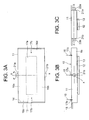
- an LCD module generally designated by reference numeral 10, according to a first embodiment of the present invention includes a transparent front panel 11, a transparent rear panel 12, and an LC layer 13 sandwiched therebetween to form a unitary body of the LCD module 10.
- the rear panel 12 has a relatively small thickness, and may be made of a non-transparent material.
- the front panel 11 has a function for protecting the LC layer 13 against a reasonable external load 15 generally applied to the portable terminal 10, such as a portable data assistant or a mobile telephone. As is well known, if the front panel 11 is deformed by the external load 15, the LC layer 13 is also deformed to affect the image passed by the LC layer 13. For prevention of such a deformation, the front panel 11 has a thickness sufficient for preventing the external load 15 from exerting an adverse influence to the LC layer 13. The front panel 11 has an area larger than the areas of the rear panel 12 and the LC layer 13, which are substantially same.
- the peripheral area 16 of the front panel 11 protruding from the edges of the rear panel 12 and the LC layer 13 is referred to as a flange 16 in this text, the flange 16 including four flange portions corresponding to the four edges of the LCD modules 10.
- external load or "reasonable external load” as used herein means a load inadvertently applied to the portable terminal 10, such as a load applied when the user sits on a seat with the portable terminal 10 received in a rear pocket of trousers, a load applied by a luggage, for example, to the portable terminal 10 received in a leather bag, or a force applied by the gravity when the portable terminal 10 falls to the ground.
- the external load has an unspecified point of application on the transparent front panel.
- Fig. 1 shows such a point of application of the external force 15 by reference numeral 17.
- a pair of through-holes 19a and 19b formed in the front panel 11 at the flange portions thereof are used in combination with respective screws or bolts 20a and 20b.
- the external load 15 hardly damages the LC layer 13 and the rear panel 12 due to substantially no deformation of the front panel 11 having a sufficient thickness.
- the LCD module 10 of the first embodiment is attached onto a casing 18 having an opening 14 for allowing a swivel movement or seesaw movement of the LCD module 10 around a swivel axis X-X extending in the direction parallel to the front surface of the casing 18 or the front panel 11.
- the swivel axis X-X is implemented by a pair of protrusions 21a and 21b formed on the top and bottom of the front panel 11 at the flange portions 16a and 16b thereof.
- the pair of protrusions 21a and 21b are supported on a pair of bearings 22a and 22b fixed onto the casing 18 so that the LCD module 10 is allowed to move in a seesaw fashion around the swivel axis X-X with respect to the casing 18.
- an external load 15 applied onto the front panel 11 at a point 17a located in the vicinity of or on the axis X-X does not swivel the LCD module 10.
- the external load 15 does not substantially generate a deformation or damage on the rear panel 12 and the LC layer 13 due to the sufficient thickness of the front panel 11.
- the LCD module 10 is swiveled without involving a damage on the LCD module 10.
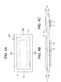
- an LCD module 10A according to a second embodiment of the present invention is similar to the LCD module 10 of the first embodiment except for a step 31 formed in the vicinity of the periphery of the front panel 10.
- the step 10 is such that the front portion 11a of the front panel 10 is smaller in size than the rear portion 11b of the front panel 10.
- the step 31 is formed by different thicknesses of the front panel 11, wherein the inner area of each flange portion 16a-16d of the front panel 11 has a larger thickness than the outer area of the each flange portion 16a-16d.
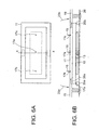
- the LCD module 10A of the second embodiment is attached onto a casing 18 having an opening 14 so that the LCD module 10A is allowed to swivel around the swivel axis X-X, with the front surface of the front panel 11 received in the opening 14.
- the swivel axis X-X is implemented by a pair of fulcrums 24a and 24b residing on the top and bottom flange portions 16a and 16b of the front panel 11 of the LCD module 10A.
- the front panel 11 is supported at both the side edges thereof by the casing 18 by means of a pair of springs 28a and 28b disposed between the casing 18 and the front surface of the flange portions 16a and 16b.
- the rear surface of the front panel 11 is supported against the springs 28a and 28b at the fulcrums 24a and 24b, located on the swivel axis X-X, by a pair of support members 32a and 32b formed on a substrate 26.
- the front surface of the central area of the front panel 11 is flush with the front surface of the casing 18 at the normal position of the LCD module 10A.
- the periphery of the front panel 11 having a lower thickness than the central area is received inside the casing 18.
- a pair of changeover switches 25a and 25b are disposed on the substrate 26 at the locations where the right and left edges of the rear surface of the front panel 11 abut the changeover switches 25a and 25b after the swivel of the LCD module 10 for on/off operations of the switches 25a and 25b.
- the changeover switches 25a and 25b are used for switching between programs which display different information on the LCD module 10A.
- a pair of support members may be formed on the casing 18 for supporting the flange portions 16a and 16b of the front panel 11 instead of the support members 32a and 32b on the substrate 26.
- the fulcrums reside on the rear surface of the casing 18.
- FIG. 6A to 6C there are shown swiveling directions of the LCD module 10A of the present embodiment by arrows 23a and 23b.
- the LCD module 10A stays at the normal position due to a small moment around the swivel axis X-X.
- the applied force is transferred onto the casing 18 and/or substrate 26.
- the sufficient thickness of the front panel 11 allows the rear panel 12 and the LC layer 13 to be substantially free from deformation. If a pair of external forces 15 are applied at both points 17b and 17c so that both the external forces 15 cancel the moment of each other with respect to the swivel axis X-X, the LCD module 10A stays at the normal position as well.
- an external force 15 is applied onto the front panel at point 17b or 17c, which is well apart from the swivel axis X-X.
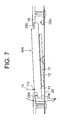
- the LCD module 10A is swiveled by the external force 15 in a seesaw function to allow one of the rear edges thereof to abut one of the changeover switches 25 and 25b, after breaking the mechanical balance between the springs 25a and 25b, as shown in Fig. 7.
- Each switch 25a or 25b has an inherent function for switching the image on the LCD module 10.
- the front panel 11 may be made of any of glass or plastic resin materials for achieving a variety of shapes for the flange portion.
- the number of flange portions may be two or four in the front panel, so long as the flange portions oppose each other.
- top or bottom flange and a right or left flange may be formed in the front panel 11 if the flange portions are not used for swiveling the LCD module 10 and simply used for fixing.
- the rear panel 12 may be either transparent or non-transparent.
- the front panel 11 may have any shape such as a polygon.
- the LC layer 13 may be made of any LC materials or an organic electroluminescence material.
- an LCD module 10B includes a front panel 11 having a first portion 11c and a second portion 11d, a rear panel 12, and an LC layer 13 sandwiched therebetween, wherein the first portion 11c has a larger thickness and functions as a protective overcoat for protecting the second portion 11d, the rear panel 12 and the LC layer 13 against an external load.
- the protective overcoat 11c also has a larger area than the area of the second portion 11d, the LC layer 13 and the rear panel 12, as viewed in the direction normal to the panels.
- the protective overcoat 11c has flange portions 16a-16d protruding from the edge of the second portion 11d in the direction parallel to the panels.
- the second portion 11d of the front panel 11 and the rear panel 12 have substantially the same thickness and the same dimensions. This structure allows the fabrication process to be simplified.
- the combination switch structure having the LCD module of the present invention may be of a single-switch type or a slide-switch type other than the seesaw-switch type shown in Figs 5A to 5C.
- Figs. 9A and 9B show a single-switch type combination switch structure having the LCD module 10 of Figs. 1A to 1C.
- a pair of elastic members or springs 42a and 42b are provided between the flange portions 16c and 16d of the front panel 11 and the substrate 26 mounting thereon the LCD module 10, urging the LCD module 10 toward the front side.
- a changeover switch 41 is disposed at the center of the rear surface of the rear panel 12 so that the changeover switch 41 is in the normal state thereof by the function of the springs 42a and 42b.
- the casing 18 having an opening 14 for exposing the front panel 11 of the LCD module 10 is fastened to the substrate 26 by screws 43a and 43b.
- Figs. 10A and 10B show a slide-switch structure having the LCD module 10A of the second embodiment.
- the flange portions 16a and 16b of the LCD module 10A are mounted on a pair of guide rails 51a and 51b, which are fixed onto a substrate 26, so that guide rails 51a and 51b allows the LCD module 10A to slide between two positions at which the steps 31 of the flange portions 16c and 16d act as stoppers on the edges of the opening 14.
- the LCD module 10A has a lever 53 which forces the switch 52 to make open or close during the slide movement of the LCD module 10A between the stoppers.
- the sufficient thickness of the front panel 11 protects the LC layer 13 and the rear panel 12 against the external force for shifting the LC module 10A between the stoppers.
Landscapes
- Physics & Mathematics (AREA)
- Nonlinear Science (AREA)
- Engineering & Computer Science (AREA)
- General Physics & Mathematics (AREA)
- Optics & Photonics (AREA)
- Crystallography & Structural Chemistry (AREA)
- Chemical & Material Sciences (AREA)
- Mathematical Physics (AREA)
- General Engineering & Computer Science (AREA)
- Theoretical Computer Science (AREA)
- Human Computer Interaction (AREA)
- Devices For Indicating Variable Information By Combining Individual Elements (AREA)
- Liquid Crystal (AREA)
- Telephone Set Structure (AREA)
Abstract
Description
Claims (9)
- A liquid crystal display (LCD) module comprising a transparent front panel (11), a rear panel (12) and a liquid crystal (LC) layer (13) sandwiched between said transparent front panel (11) and said rear panel (12), characterized in that:said transparent front panel (11) has a central area opposing areas of said LC layer (13) and said rear panel (12) and a peripheral area (16) extending from said central area, and said transparent front panel (11) has a thickness larger than a thickness of said rear panel (12).
- The LCD module as defined in claim 1, wherein said peripheral area (16) has a plurality of holes (19a, 19b) for receiving screws (20a, 20b).
- The LCD module as defined in claim 1, wherein said peripheral area (16) includes a pair of flange portions (16a, 16b; 16c, 16d) extending from said central area.
- The LCD module as defined in claim 1, wherein said central area has a thickness larger than a thickness of said peripheral area (16), whereby a step is formed in a vicinity of a boundary between said central area and said peripheral area (16).
- The LCD module as defined in claim 1, wherein said transparent front panel (11) comprises a first portion having a thickness substantially equal to a thickness of said rear panel, and an second portion covering said first portion.
- A combination switch structure comprising:a liquid crystal (LCD) module (10, 10A, 10B) including a transparent front panel (11), a rear panel (12) and a liquid crystal (LC) layer (13) sandwiched between said transparent front panel (11) and said rear panel (129; anda switch member (25a, 25b, 41, 52) operated by a movement of said front panel (11) when said transparent front panel (11) is applied with an external force, characterized in that:said transparent front panel (11) has a central area opposing areas of said LC layer (13) and said rear panel (12) and a peripheral area (16) extending from said central area, and wherein said switch member (25a, 25b, 41, 52) is operated by the movement of said peripheral area (16).
- The combination switch structure as defined in claim 6, further comprising at least one elastic member (28a, 28b; 42a, 42b) for urging said LCD module (10, 10A, 10B), wherein said switch member (25a, 25b, 41, 52) is pressed by pressing said transparent front panel (10, 10A, 10B) against said elastic member (28a, 28b; 42a, 42b).
- The combination switch structure as defined in claim 7, wherein said at least one elastic member (28a, 28b) includes a pair of springs, and said LCD module (10A) swivels around a swivel axis (X-X) when said transparent panel (11) is pressed.
- The combination switch structure as defined in claim 6, further comprising a guide member (51a, 51b) fixed with respect to a casing (18) for guiding said LCD module (10A) along a surface of said casing (18), wherein said switch member (52) is operated by a slide movement of said peripheral area (16).
Applications Claiming Priority (2)
| Application Number | Priority Date | Filing Date | Title |
|---|---|---|---|
| JP2001050328A JP2002250911A (en) | 2001-02-26 | 2001-02-26 | Liquid crystal module and switching structure which uses liquid crystal module |
| JP2001050328 | 2001-02-26 |
Publications (2)
| Publication Number | Publication Date |
|---|---|
| EP1235098A2 true EP1235098A2 (en) | 2002-08-28 |
| EP1235098A3 EP1235098A3 (en) | 2007-06-20 |
Family
ID=18911302
Family Applications (1)
| Application Number | Title | Priority Date | Filing Date |
|---|---|---|---|
| EP02004144A Withdrawn EP1235098A3 (en) | 2001-02-26 | 2002-02-25 | LCD module and a combination switch using the same |
Country Status (5)
| Country | Link |
|---|---|
| US (2) | US6853432B2 (en) |
| EP (1) | EP1235098A3 (en) |
| JP (1) | JP2002250911A (en) |
| CN (1) | CN1232868C (en) |
| HK (1) | HK1050396A1 (en) |
Cited By (3)
| Publication number | Priority date | Publication date | Assignee | Title |
|---|---|---|---|---|
| FR2918499A1 (en) * | 2007-06-12 | 2009-01-09 | Johnson Controis Technology Co | Key element actuating and functional symbol displaying device for e.g. air conditioning system, of motor vehicle, has guiding element defining curve such that actuation of key element corresponds to movement of key element along curve |
| EP2658223A1 (en) * | 2012-04-27 | 2013-10-30 | Samsung Electronics Co., Ltd. | Portable Terminal with Crack Prevention Structure for Display Device |
| WO2018029172A1 (en) * | 2016-08-08 | 2018-02-15 | Audi Ag | Haptic feedback for a screen |
Families Citing this family (39)
| Publication number | Priority date | Publication date | Assignee | Title |
|---|---|---|---|---|
| US5910854A (en) | 1993-02-26 | 1999-06-08 | Donnelly Corporation | Electrochromic polymeric solid films, manufacturing electrochromic devices using such solid films, and processes for making such solid films and devices |
| US5668663A (en) | 1994-05-05 | 1997-09-16 | Donnelly Corporation | Electrochromic mirrors and devices |
| US6891563B2 (en) | 1996-05-22 | 2005-05-10 | Donnelly Corporation | Vehicular vision system |
| US6124886A (en) | 1997-08-25 | 2000-09-26 | Donnelly Corporation | Modular rearview mirror assembly |
| US6326613B1 (en) | 1998-01-07 | 2001-12-04 | Donnelly Corporation | Vehicle interior mirror assembly adapted for containing a rain sensor |
| US8294975B2 (en) | 1997-08-25 | 2012-10-23 | Donnelly Corporation | Automotive rearview mirror assembly |
| US6172613B1 (en) | 1998-02-18 | 2001-01-09 | Donnelly Corporation | Rearview mirror assembly incorporating vehicle information display |
| US6445287B1 (en) | 2000-02-28 | 2002-09-03 | Donnelly Corporation | Tire inflation assistance monitoring system |
| US8288711B2 (en) | 1998-01-07 | 2012-10-16 | Donnelly Corporation | Interior rearview mirror system with forwardly-viewing camera and a control |
| US6693517B2 (en) | 2000-04-21 | 2004-02-17 | Donnelly Corporation | Vehicle mirror assembly communicating wirelessly with vehicle accessories and occupants |
| US6477464B2 (en) | 2000-03-09 | 2002-11-05 | Donnelly Corporation | Complete mirror-based global-positioning system (GPS) navigation solution |
| US6329925B1 (en) | 1999-11-24 | 2001-12-11 | Donnelly Corporation | Rearview mirror assembly with added feature modular display |
| WO2001064481A2 (en) | 2000-03-02 | 2001-09-07 | Donnelly Corporation | Video mirror systems incorporating an accessory module |
| US7370983B2 (en) | 2000-03-02 | 2008-05-13 | Donnelly Corporation | Interior mirror assembly with display |
| US7195381B2 (en) | 2001-01-23 | 2007-03-27 | Donnelly Corporation | Vehicle interior LED lighting system |
| US7167796B2 (en) | 2000-03-09 | 2007-01-23 | Donnelly Corporation | Vehicle navigation system for use with a telematics system |
| US7581859B2 (en) | 2005-09-14 | 2009-09-01 | Donnelly Corp. | Display device for exterior rearview mirror |
| US7255451B2 (en) | 2002-09-20 | 2007-08-14 | Donnelly Corporation | Electro-optic mirror cell |
| US6918674B2 (en) | 2002-05-03 | 2005-07-19 | Donnelly Corporation | Vehicle rearview mirror system |
| WO2003105099A1 (en) | 2002-06-06 | 2003-12-18 | Donnelly Corporation | Interior rearview mirror system with compass |
| US7329013B2 (en) | 2002-06-06 | 2008-02-12 | Donnelly Corporation | Interior rearview mirror system with compass |
| US7274501B2 (en) | 2002-09-20 | 2007-09-25 | Donnelly Corporation | Mirror reflective element assembly |
| US7310177B2 (en) | 2002-09-20 | 2007-12-18 | Donnelly Corporation | Electro-optic reflective element assembly |
| JP2004240878A (en) * | 2003-02-07 | 2004-08-26 | Nec Corp | Portable electronic appliance, display direction switching method and program |
| US7446924B2 (en) | 2003-10-02 | 2008-11-04 | Donnelly Corporation | Mirror reflective element assembly including electronic component |
| US7308341B2 (en) | 2003-10-14 | 2007-12-11 | Donnelly Corporation | Vehicle communication system |
| CN100407095C (en) * | 2004-07-23 | 2008-07-30 | 华硕电脑股份有限公司 | Electronic device with screen protection function |
| EP1883855B1 (en) | 2005-05-16 | 2011-07-20 | Donnelly Corporation | Vehicle mirror assembly with indicia at reflective element |
| CN101535087B (en) | 2005-11-01 | 2013-05-15 | 唐纳利公司 | Interior rearview mirror with display |
| KR20100015501A (en) * | 2007-03-15 | 2010-02-12 | 에프-오리진, 인크. | Integrated feature for friction-less movement of force sensitive touch screen |
| EP2083348A1 (en) * | 2008-01-21 | 2009-07-29 | Visiocorp Patents S.à.r.l. | Touch screen switching assembly |
| US8154418B2 (en) | 2008-03-31 | 2012-04-10 | Magna Mirrors Of America, Inc. | Interior rearview mirror system |
| WO2012111349A1 (en) * | 2011-02-18 | 2012-08-23 | 京セラ株式会社 | Electronic device |
| USD735144S1 (en) | 2012-10-25 | 2015-07-28 | Cooper Technologies Company | Touch screen wiring device |
| CN103117026A (en) * | 2012-12-26 | 2013-05-22 | 苏州佳世达电通有限公司 | Display device with solid keys |
| JP2014157311A (en) * | 2013-02-18 | 2014-08-28 | Japan Display Inc | Display device and manufacturing method of display device |
| KR20140122433A (en) * | 2013-04-10 | 2014-10-20 | 삼성디스플레이 주식회사 | Mobile device and method of shape change a mobile device |
| EP3067909B1 (en) * | 2015-03-11 | 2017-10-18 | Siemens Aktiengesellschaft | Contact pusher unit for a switching unit |
| CN119032334A (en) * | 2023-03-24 | 2024-11-26 | 京东方科技集团股份有限公司 | Haptic feedback module and electronic device |
Family Cites Families (20)
| Publication number | Priority date | Publication date | Assignee | Title |
|---|---|---|---|---|
| JPS50121756U (en) * | 1974-03-18 | 1975-10-04 | ||
| JPS5823607B2 (en) * | 1977-09-22 | 1983-05-16 | シャープ株式会社 | Multilayer matrix type liquid crystal display device |
| JPS58102148A (en) * | 1981-12-14 | 1983-06-17 | Kawasaki Steel Corp | On-line hardness measuring method for steel sheet |
| US4623222A (en) * | 1983-11-14 | 1986-11-18 | Nippondenso Co., Ltd. | Liquid crystal type dazzle-free transmissive-reflective mirror |
| DE8334346U1 (en) * | 1983-11-30 | 1984-03-22 | Mueller, Rolf, Dr., 6750 Kaiserslautern | DEVICE, ESPECIALLY FOR TYPEWRITERS AND TERMINALS |
| JPH0682765B2 (en) * | 1985-12-25 | 1994-10-19 | 株式会社日立製作所 | Liquid crystal display element |
| JPS62176879A (en) | 1986-01-30 | 1987-08-03 | Ricoh Co Ltd | Thermal recording material |
| JPS62176879U (en) * | 1986-04-28 | 1987-11-10 | ||
| JPH07121097B2 (en) * | 1988-11-18 | 1995-12-20 | 株式会社日立製作所 | Liquid crystal television and manufacturing method thereof |
| DE69423552T2 (en) * | 1993-08-10 | 2000-09-07 | Canon K.K., Tokio/Tokyo | Liquid crystal display |
| US5808707A (en) * | 1995-03-01 | 1998-09-15 | Canon Kabushiki Kaisha | Display apparatus |
| JPH0990316A (en) * | 1995-09-20 | 1997-04-04 | Optrex Corp | Liquid crystal display device with touch panel |
| JPH09146078A (en) * | 1995-11-16 | 1997-06-06 | Canon Inc | Liquid crystal element, method of manufacturing liquid crystal element, and liquid crystal device using the same |
| JPH10104418A (en) | 1996-10-03 | 1998-04-24 | Toray Ind Inc | Liquid crystal display device substrate and liquid crystal display device |
| US5804780A (en) * | 1996-12-31 | 1998-09-08 | Ericsson Inc. | Virtual touch screen switch |
| JP3296993B2 (en) * | 1997-04-08 | 2002-07-02 | エルジー フィリップス エルシーディー カンパニー リミテッド | Portable computer with liquid crystal display |
| DE69709053T2 (en) * | 1997-04-17 | 2002-07-18 | Asulab S.A., Biel/Bienne | Liquid crystal display device for a color screen |
| JP4136090B2 (en) | 1998-06-30 | 2008-08-20 | キヤノン株式会社 | Image forming apparatus |
| JP2000194004A (en) * | 1998-07-29 | 2000-07-14 | Citizen Watch Co Ltd | Reflection type liquid crystal color display device |
| JP2000267788A (en) * | 1999-03-16 | 2000-09-29 | Olympus Optical Co Ltd | Equipment having information display means |
-
2001
- 2001-02-26 JP JP2001050328A patent/JP2002250911A/en active Pending
-
2002
- 2002-02-19 US US10/076,354 patent/US6853432B2/en not_active Expired - Fee Related
- 2002-02-25 EP EP02004144A patent/EP1235098A3/en not_active Withdrawn
- 2002-02-26 CN CNB021054339A patent/CN1232868C/en not_active Expired - Fee Related
-
2003
- 2003-03-25 HK HK03102159.0A patent/HK1050396A1/en unknown
-
2005
- 2005-01-07 US US11/030,187 patent/US7248305B2/en not_active Expired - Fee Related
Cited By (6)
| Publication number | Priority date | Publication date | Assignee | Title |
|---|---|---|---|---|
| FR2918499A1 (en) * | 2007-06-12 | 2009-01-09 | Johnson Controis Technology Co | Key element actuating and functional symbol displaying device for e.g. air conditioning system, of motor vehicle, has guiding element defining curve such that actuation of key element corresponds to movement of key element along curve |
| EP2658223A1 (en) * | 2012-04-27 | 2013-10-30 | Samsung Electronics Co., Ltd. | Portable Terminal with Crack Prevention Structure for Display Device |
| CN103379777A (en) * | 2012-04-27 | 2013-10-30 | 三星电子株式会社 | Portable terminal with crack prevention structure for display device |
| US9380714B2 (en) | 2012-04-27 | 2016-06-28 | Samsung Electronics Co., Ltd. | Portable terminal with crack prevention structure for display device |
| CN103379777B (en) * | 2012-04-27 | 2017-09-22 | 三星电子株式会社 | Portable terminal with the anti-cracking structure for display device |
| WO2018029172A1 (en) * | 2016-08-08 | 2018-02-15 | Audi Ag | Haptic feedback for a screen |
Also Published As
| Publication number | Publication date |
|---|---|
| US20050117084A1 (en) | 2005-06-02 |
| CN1232868C (en) | 2005-12-21 |
| JP2002250911A (en) | 2002-09-06 |
| HK1050396A1 (en) | 2003-06-20 |
| CN1372159A (en) | 2002-10-02 |
| EP1235098A3 (en) | 2007-06-20 |
| US7248305B2 (en) | 2007-07-24 |
| US20020118319A1 (en) | 2002-08-29 |
| US6853432B2 (en) | 2005-02-08 |
Similar Documents
| Publication | Publication Date | Title |
|---|---|---|
| US6853432B2 (en) | LCD module and a combination switch using the same | |
| EP1507273B1 (en) | Keypad assembly | |
| US7747007B2 (en) | Protective cover for portable communication device | |
| EP1748628B1 (en) | Slim portable terminal | |
| EP1775596B1 (en) | Keypad for sliding-type portable terminal | |
| KR100656810B1 (en) | Electronic device with variable keyboard | |
| EP3879799B1 (en) | Folding display device | |
| US20050079902A1 (en) | Positioning apparatus and method for a slide cover | |
| KR20010024946A (en) | Hinge assemblies for electronic devices | |
| KR100993095B1 (en) | Clamshell mobile devices | |
| EP1265127A2 (en) | A removable keyboard attachment for information devices | |
| KR20110090656A (en) | Metal Dome Switch Integrated Touch Window of Mobile Device | |
| RU2358351C2 (en) | Mobile terminal with shock absorber | |
| US20130040701A1 (en) | Portable communication device | |
| EP1924056B1 (en) | Folding type mobile terminal | |
| JP2004172454A (en) | Portable electronic apparatus | |
| EP2367338B1 (en) | Electronic device including a front bezel operable to keep the device together | |
| JP2007036905A (en) | Mobile terminal device | |
| US7664256B2 (en) | Mobile terminal apparatus | |
| US8862190B2 (en) | Portable electronic device with upper housing and cover plate therefor | |
| US20120190759A1 (en) | Keymat and screen structure and method of assembling | |
| US20110222223A1 (en) | Folding portable electronic device | |
| CA2731763C (en) | Portable electronic device with upper housing and cover plate therefor | |
| CN121039598A (en) | Electronic devices including hinge devices | |
| KR20240156911A (en) | Electronic device including hinge device |
Legal Events
| Date | Code | Title | Description |
|---|---|---|---|
| PUAI | Public reference made under article 153(3) epc to a published international application that has entered the european phase |
Free format text: ORIGINAL CODE: 0009012 |
|
| AK | Designated contracting states |
Kind code of ref document: A2 Designated state(s): AT BE CH CY DE DK ES FI FR GB GR IE IT LI LU MC NL PT SE TR |
|
| AX | Request for extension of the european patent |
Free format text: AL;LT;LV;MK;RO;SI |
|
| PUAL | Search report despatched |
Free format text: ORIGINAL CODE: 0009013 |
|
| AK | Designated contracting states |
Kind code of ref document: A3 Designated state(s): AT BE CH CY DE DK ES FI FR GB GR IE IT LI LU MC NL PT SE TR |
|
| AX | Request for extension of the european patent |
Extension state: AL LT LV MK RO SI |
|
| 17P | Request for examination filed |
Effective date: 20070524 |
|
| 17Q | First examination report despatched |
Effective date: 20071115 |
|
| AKX | Designation fees paid |
Designated state(s): DE FR GB IT |
|
| STAA | Information on the status of an ep patent application or granted ep patent |
Free format text: STATUS: THE APPLICATION HAS BEEN WITHDRAWN |
|
| 18W | Application withdrawn |
Effective date: 20091008 |