EP1234958A2 - A method of and apparatus for controlling quantity of air drawn into internal combustion engine - Google Patents
A method of and apparatus for controlling quantity of air drawn into internal combustion engine Download PDFInfo
- Publication number
- EP1234958A2 EP1234958A2 EP02003761A EP02003761A EP1234958A2 EP 1234958 A2 EP1234958 A2 EP 1234958A2 EP 02003761 A EP02003761 A EP 02003761A EP 02003761 A EP02003761 A EP 02003761A EP 1234958 A2 EP1234958 A2 EP 1234958A2
- Authority
- EP
- European Patent Office
- Prior art keywords
- valve
- low load
- intake
- operating range
- engine
- Prior art date
- Legal status (The legal status is an assumption and is not a legal conclusion. Google has not performed a legal analysis and makes no representation as to the accuracy of the status listed.)
- Granted
Links
Images

Classifications
-
- F—MECHANICAL ENGINEERING; LIGHTING; HEATING; WEAPONS; BLASTING
- F02—COMBUSTION ENGINES; HOT-GAS OR COMBUSTION-PRODUCT ENGINE PLANTS
- F02D—CONTROLLING COMBUSTION ENGINES
- F02D13/00—Controlling the engine output power by varying inlet or exhaust valve operating characteristics, e.g. timing
- F02D13/02—Controlling the engine output power by varying inlet or exhaust valve operating characteristics, e.g. timing during engine operation
- F02D13/0223—Variable control of the intake valves only
- F02D13/0226—Variable control of the intake valves only changing valve lift or valve lift and timing
-
- F—MECHANICAL ENGINEERING; LIGHTING; HEATING; WEAPONS; BLASTING
- F01—MACHINES OR ENGINES IN GENERAL; ENGINE PLANTS IN GENERAL; STEAM ENGINES
- F01L—CYCLICALLY OPERATING VALVES FOR MACHINES OR ENGINES
- F01L13/00—Modifications of valve-gear to facilitate reversing, braking, starting, changing compression ratio, or other specific operations
- F01L13/0015—Modifications of valve-gear to facilitate reversing, braking, starting, changing compression ratio, or other specific operations for optimising engine performances by modifying valve lift according to various working parameters, e.g. rotational speed, load, torque
- F01L13/0021—Modifications of valve-gear to facilitate reversing, braking, starting, changing compression ratio, or other specific operations for optimising engine performances by modifying valve lift according to various working parameters, e.g. rotational speed, load, torque by modification of rocker arm ratio
-
- F—MECHANICAL ENGINEERING; LIGHTING; HEATING; WEAPONS; BLASTING
- F02—COMBUSTION ENGINES; HOT-GAS OR COMBUSTION-PRODUCT ENGINE PLANTS
- F02M—SUPPLYING COMBUSTION ENGINES IN GENERAL WITH COMBUSTIBLE MIXTURES OR CONSTITUENTS THEREOF
- F02M26/00—Engine-pertinent apparatus for adding exhaust gases to combustion-air, main fuel or fuel-air mixture, e.g. by exhaust gas recirculation [EGR] systems
- F02M26/01—Internal exhaust gas recirculation, i.e. wherein the residual exhaust gases are trapped in the cylinder or pushed back from the intake or the exhaust manifold into the combustion chamber without the use of additional passages
-
- F—MECHANICAL ENGINEERING; LIGHTING; HEATING; WEAPONS; BLASTING
- F01—MACHINES OR ENGINES IN GENERAL; ENGINE PLANTS IN GENERAL; STEAM ENGINES
- F01L—CYCLICALLY OPERATING VALVES FOR MACHINES OR ENGINES
- F01L13/00—Modifications of valve-gear to facilitate reversing, braking, starting, changing compression ratio, or other specific operations
- F01L13/0015—Modifications of valve-gear to facilitate reversing, braking, starting, changing compression ratio, or other specific operations for optimising engine performances by modifying valve lift according to various working parameters, e.g. rotational speed, load, torque
- F01L13/0063—Modifications of valve-gear to facilitate reversing, braking, starting, changing compression ratio, or other specific operations for optimising engine performances by modifying valve lift according to various working parameters, e.g. rotational speed, load, torque by modification of cam contact point by displacing an intermediate lever or wedge-shaped intermediate element, e.g. Tourtelot
- F01L2013/0073—Modifications of valve-gear to facilitate reversing, braking, starting, changing compression ratio, or other specific operations for optimising engine performances by modifying valve lift according to various working parameters, e.g. rotational speed, load, torque by modification of cam contact point by displacing an intermediate lever or wedge-shaped intermediate element, e.g. Tourtelot with an oscillating cam acting on the valve of the "Delphi" type
-
- F—MECHANICAL ENGINEERING; LIGHTING; HEATING; WEAPONS; BLASTING
- F02—COMBUSTION ENGINES; HOT-GAS OR COMBUSTION-PRODUCT ENGINE PLANTS
- F02D—CONTROLLING COMBUSTION ENGINES
- F02D13/00—Controlling the engine output power by varying inlet or exhaust valve operating characteristics, e.g. timing
- F02D13/02—Controlling the engine output power by varying inlet or exhaust valve operating characteristics, e.g. timing during engine operation
- F02D13/0261—Controlling the valve overlap
-
- Y—GENERAL TAGGING OF NEW TECHNOLOGICAL DEVELOPMENTS; GENERAL TAGGING OF CROSS-SECTIONAL TECHNOLOGIES SPANNING OVER SEVERAL SECTIONS OF THE IPC; TECHNICAL SUBJECTS COVERED BY FORMER USPC CROSS-REFERENCE ART COLLECTIONS [XRACs] AND DIGESTS
- Y02—TECHNOLOGIES OR APPLICATIONS FOR MITIGATION OR ADAPTATION AGAINST CLIMATE CHANGE
- Y02T—CLIMATE CHANGE MITIGATION TECHNOLOGIES RELATED TO TRANSPORTATION
- Y02T10/00—Road transport of goods or passengers
- Y02T10/10—Internal combustion engine [ICE] based vehicles
- Y02T10/12—Improving ICE efficiencies
-
- Y—GENERAL TAGGING OF NEW TECHNOLOGICAL DEVELOPMENTS; GENERAL TAGGING OF CROSS-SECTIONAL TECHNOLOGIES SPANNING OVER SEVERAL SECTIONS OF THE IPC; TECHNICAL SUBJECTS COVERED BY FORMER USPC CROSS-REFERENCE ART COLLECTIONS [XRACs] AND DIGESTS
- Y02—TECHNOLOGIES OR APPLICATIONS FOR MITIGATION OR ADAPTATION AGAINST CLIMATE CHANGE
- Y02T—CLIMATE CHANGE MITIGATION TECHNOLOGIES RELATED TO TRANSPORTATION
- Y02T10/00—Road transport of goods or passengers
- Y02T10/10—Internal combustion engine [ICE] based vehicles
- Y02T10/40—Engine management systems
Abstract
Description
- The present invention relates to a method of and apparatus for controlling a quantity of air drawn into engine cylinders, and particularly to technologies for controlling a quantity of air entering engine cylinders by variably adjusting operating characteristics of an intake valve.
- On gasoline engines, an amount of air drawn into the engine is generally controlled by adjusting a throttle opening of a throttle valve disposed in an air intake passage of an induction system. In this type of gasoline engine, there is a great pumping loss under low load conditions wherein the throttle valve is kept at a less throttle opening. In recent years, there have been proposed and developed various engines employing a variable valve actuation system such as a variable valve timing and lift control system, a variable valve event and lift control system, and the like. On such variable valve actuation system equipped engines, an intake air quantity is controlled by variably adjusting an engine valve timing, in particular an intake valve closure timing (IVC) and/or a valve lift of the intake valve, instead of using throttle opening adjustment. One such variable valve actuation system equipped internal combustion engine has been disclosed in Japanese Patent Provisional Publication No. 11-117777 (hereinafter is referred to as "JP11-117777" and corresponding to U.S. Pat. No. 6,039,026 issued March 21, 2000). In the variable valve actuation system equipped engine as disclosed in JP11-117777, intake and exhaust valves are constructed by electromagnetically-controlled engine valves. Taking into account a less pumping loss, during low and mid engine load operations, an intake air quantity is controlled by variably controlling a valve closure timing of the electromagnetically-controlled intake valve or a lift of the intake valve, while the throttle opening is adjusted to a predetermined value corresponding to a substantially full-throttle position. In contrast, at idling or during excessively low load operations and at high load operations, the intake air quantity is controlled by way of throttle opening adjustment.
- The intake air quantity control based on variable valve timing control (in particular, variable intake valve closure timing control) has the following drawback. According to the IVC control, the intake valve closure timing has to be advanced gradually from a B.D.C. position (bottom dead center) as the engine load decreases. Therefore, during excessively low load operations such as at idling, there is an increased tendency for the IVC to be controlled to a timing point closer to a T.D.C position (top dead center). In other words, the intake valve tends to close at a timing that the reciprocating piston does not yet move down sufficiently. This reduces an effective compression ratio. In such a case, adequate pressure and temperature cannot be obtained at the BDC on compression stroke, and thereby combustion is deteriorated.
- In contrast to the above, when controlling the intake air quantity only by way of valve-lift control instead of using the IVC control, the intake valve itself acts as a flow constricting orifice or a throttling orifice. Therefore, in case of only the valve-lift control, it is impossible to satisfactorily reduce the pumping loss.
- Accordingly, it is an object of the invention to provide a method of and apparatus for controlling a quantity of air drawn into an internal combustion engine, which avoids the aforementioned disadvantages.
- It is another object of the invention to provide a method of and apparatus for controlling an intake air quantity, which is capable of realizing intake air quantity control independent of throttle opening control, while adequately reducing a pumping loss by simultaneously varying both an intake valve closure timing and a working angle of the intake valve, and of avoiding combustion from being deteriorated during very low load operation such as at idling.
- It is a further object of the invention to provide a method of and apparatus for controlling an intake air quantity, which is capable of realizing stable intake air quantity control at very low load operation for a long term without being affected by any deposits that have formed on the valve face or valve edge of the intake valve.
- In order to accomplish the aforementioned and other objects of the present invention, a method of continuously controlling a quantity of air drawn into an internal combustion engine by varying operating characteristics of an intake valve, the method comprises using a valve lift included in a range wherein the quantity of air is determined only by a valve lift and a working angle of the intake valve, in a very low load operating range containing during idling, and using a valve lift included in a range wherein the quantity of air is determined by the valve lift and the working angle of the intake valve, and a phase of a central angle of the working angle of the intake valve, in operating ranges except the very low load operating range.
- According to another aspect of the invention, an apparatus for continuously controlling a quantity of air drawn into an internal combustion engine by varying operating characteristics of an intake valve, the apparatus comprises a first variable mechanism that continuously varies both a valve lift and a working angle of the intake valve, a second variable mechanism that varies a phase of a central angle of the working angle of the intake valve, a control unit configured to be electronically connected to the first and second variable mechanisms for variably controlling the quantity of air drawn into the engine, the control unit using a valve lift included in a range wherein the quantity of air is determined only by the valve lift and the working angle of the intake valve, in a very low load operating range containing during idling, and the control unit using a valve lift included in a range wherein the quantity of air is determined by the valve lift and the working angle of the intake valve, and the phase of the central angle, in operating ranges except the very low load operating range.
- The other objects and features of this invention will become understood from the following description with reference to the accompanying drawings.
-
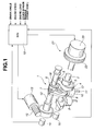
- Fig. 1 is a perspective view illustrating a variable valve actuation system incorporated in an intake air quantity control system of one embodiment.
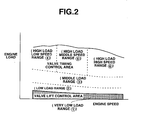
- Fig. 2 is a characteristic map showing both a valve lift control area and a valve timing control area.
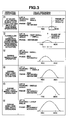
- Fig. 3 is an explanatory view showing valve operating characteristics under various engine/vehicle operating conditions.
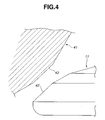
- Fig. 4 is an enlarged view illustrating an essential part of the intake valve and valve seat.
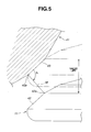
- Fig. 5 is an explanatory view showing a specified condition that a fluid passage area defined between a valve seating face of the intake valve and a valve-seat face corresponds to a minimum fluid passage area in comparison with a fluid passage area at any other section.
- Fig. 6 is a longitudinal cross section showing a tappet equipped with a built-in valve clearance adjuster.
-
- Referring now to the drawings, particularly to Fig. 1, the method of and apparatus for controlling an intake air quantity is exemplified in a spark-ignited gasoline engine for an automotive vehicle. Fig. 4 shows the variable valve actuation system incorporated in the intake air quantity control system of the embodiment. The variable valve actuation system has a mechanical valve actuation mechanism that an
intake valve 11 is driven in synchronization with rotation of an engine crankshaft. The variable valve actuation system has two different control mechanisms, namely a variable lift and working-angle control mechanism 1 and a variablephase control mechanism 21 combined with each other. Variable lift and working-angle control mechanism 1 functions to change (increase or decrease) both a valve lift and a working angle ofintake valve 11, depending on engine/vehicle operating conditions. Variablephase control mechanism 21 functions to change (advance or retard) the angular phase at the maximum valve lift point (at the central angle of the working angle). - The fundamental structure of variable lift and working-
angle control mechanism 1 is hereunder described briefly in reference to Fig. 1. - Variable lift and working-
angle control mechanism 1 is comprised of adrive shaft 2 rotatably supported by a cam bracket (not shown) located on the upper portion of a cylinder head (not shown), a firsteccentric cam 3 fixedly connected to driveshaft 2 byway of press-fitting, acontrol shaft 12 which is rotatably supported by the same cam bracket above the drive shaft and arranged parallel to the drive shaft and has a secondeccentric cam 18, arocker arm 6 oscillatingly or rockably supported on secondeccentric cam 18, and arockable cam 9 which is in abutted-engagement with atappet 10 attached to the upper portion of the valve stem ofintake valve 11. Firsteccentric cam 3 androcker arm 6 are mechanically linked to each other through alink arm 4 that rotates relative to firsteccentric cam 3. On the other hand,rocker arm 6 androckable cam 9 are linked to each other through alink member 8, so that the oscillating motion ofrocker arm 6 is produced bylink arm 4.Drive shaft 2 is driven by the engine crankshaft via a timing chain or a timing belt. Firsteccentric cam 3 is cylindrical in shape. The central axis of the cylindrical outer peripheral surface of firsteccentric cam 3 is eccentric to the axis ofdrive shaft 2 by a predetermined eccentricity. A substantially annular portion oflink arm 4 is rotatably fitted onto the cylindrical outer peripheral surface of firsteccentric cam 3. Rockerarm 6 is oscillatingly supported at its substantially central portion by secondeccentric cam 18 ofcontrol shaft 12. A protruded portion oflink arm 4 is linked to one end ofrocker arm 10 by means of a connectingpin 5. The upper end oflink member 8 is linked to the other end ofrocker arm 6 by means of a connectingpin 7. The axis of secondeccentric cam 18 is eccentric to the axis ofcontrol shaft 12, and thus the center of oscillating motion ofrocker arm 6 can be varied by changing the angular position ofcontrol shaft 12.Rockable cam 9 is rotatably fitted onto the outer periphery ofdrive shaft 2. One end ofrockable cam 9 is linked tolink member 8 by means of a connectingpin 17.Rockable cam 9 is formed on its lower surface with a base-circle surface portion being concentric to driveshaft 2 and a moderately-curved cam surface portion being continuous with the base-circle surface portion and extending toward the one end portion ofrockable cam 9. The base-circle surface portion and the cam surface portion ofrockable cam 9 are designed to be brought into abutted-contact (sliding-contact) with a designated point or a designated position of the upper surface of the associated intake-valve tappet 10, depending on an angular position ofrockable cam 9 oscillating. That is, the base-circle surface portion functions as a base-circle section within which a valve lift is zero. A predetermined angular range of the cam surface portion being continuous with the base-circle surface portion functions as a ramp section. A predetermined angular range of a cam nose portion of the cam surface portion being continuous with the ramp section functions as a lift section. Returning again to Fig. 1,control shaft 12 of variable lift and working-angle control mechanism 1 is driven within a predetermined angular range by means of a lift and working-angle control actuator 13. In the shown embodiment, lift and working-angle control actuator 13 is comprised of a geared motor composed of aworm 15 plus worm wheel, and a servo motor having a driving connection withcontrol shaft 12. The servomotor is controlled in response to a control signal from an electronic engine control unit (ECU) 19. Instead of using such a servomotor-driven actuator, a hydraulic actuator may be used as lift and working-angle control actuator 13. In this case, a controlled pressure applied to the hydraulic actuator is regulated by way of a hydraulic control module that is responsive to a control signal fromECU 19.Actuator 13 is designed so that the angular position of the output shaft ofactuator 13 is forced toward and held at an initial angular position by a return spring withactuator 13 de-activated. In a state that actuator 13 is kept at the initial angular position, the intake valve is operated with the valve lift reduced and the working angle reduced. The angular position ofcontrol shaft 12 is detected by a control-shaft sensor 14. Variable lift and working-angle control mechanism 1 operates as follows . - During rotation of
drive shaft 2,link arm 4 moves up and down by virtue of cam action of firsteccentric cam 3. The up-and-down motion oflink arm 4 causes oscillating motion ofrocker arm 6. The oscillating motion ofrocker arm 6 is transmitted vialink member 8 torockable cam 9, and thusrockable cam 9 oscillates. By virtue of cam action ofrockable cam 9 oscillating, intake-valve tappet 10 is pushed and thereforeintake valve 11 lifts. If the angular position ofcontrol shaft 12 is varied byactuator 13, an initial position ofrocker arm 6 varies and as a result an initial position (or a starting point) of the oscillating motion ofrockable cam 9. Assuming that the angular position of secondeccentric cam 18 is shifted from a first angular position that the axis of secondeccentric cam 18 is located just under the axis ofcontrol shaft 12 to a second angular position that the axis of secondeccentric cam 18 is located just above the axis ofcontrol shaft 12, as awhole rocker arm 6 shifts upwards. As a result, the one end portion ofrockable cam 9 is relatively pulled upwards. That is, the initial position (the starting point) ofrockable cam 9 is shifted so that the rockable cam itself is inclined in a direction that the cam surface portion ofrockable cam 9 moves apart from intake-valve tappet 10. Withrocker arm 6 shifted upwards, whenrockable cam 9 oscillates during rotation ofdrive shaft 2, the base-circle surface portion is held in contact with intake-valve tappet 10 for a comparatively long time period. In other words, a time period within which the cam surface portion is held in contact with intake-valve tappet 10 becomes short. As a consequence, a valve lift becomes small.
Additionally, a lifted period (i.e., a working angle ) from an intake-valve open timing (IVO) to an intake-valve closure timing (IVC) becomes reduced. - Conversely when the angular position of second
eccentric cam 18 is shifted from the second angular position that the axis of secondeccentric cam 18 is located just above the axis ofcontrol shaft 12 to the first angular position that the axis of secondeccentric cam 18 is located just under the axis ofcontrol shaft 12, as awhole rocker arm 6 shifts downwards. As a result, the one end portion ofrockable cam 9 is relatively pushed down. That is, the initial position (the starting point) ofrockable cam 9 is shifted so that the rockable cam itself is inclined in a direction that the cam surface portion ofrockable cam 9 moves towards intake-valve tappet 10. Withrocker arm 6 shifted downwards, whenrockable cam 9 oscillates during rotation ofdrive shaft 2, a portion that is brought into contact with intake-valve tappet 10 is somewhat shifted from the base-circle surface portion to the cam surface portion. As a consequence, a valve lift becomes large. Additionally, a lifted period (i.e., a working angle ) from intake-valve open timing IVO to intake-valve closure timing IVC becomes extended. The angular position of secondeccentric cam 18 can be continuously varied within limits by means ofactuator 13, and thus valve operating characteristics (valve lift and working angle) also vary continuously (see Fig. 3). As can be seen from the valve operating characteristics of Fig. 3, variable lift and working-angle control mechanism 1 can scale up and down both the valve lift and the working angle continuously simultaneously. The variable lift and working-angle control mechanism 1 incorporated in the intake air quantity control system of the embodiment, in accordance with a change in valve lift and a change in working angle , intake-valve open timing IVO and intake-valve closure timing IVC vary symmetrically with each other. Details of such a variable lift and working-angle control mechanism being set forth, for example, in U.S. Pat. No. 5,988,125 (corresponding to Japanese Patent Provisional Publication No. 11-107725) issued November 23, 1999 to Seinosuke HARA et al., the teachings of which are hereby incorporated by reference. - Returning to Fig. 1, variable
phase control mechanism 21 is comprised of asprocket 22 and aphase control actuator 23.Sprocket 22 is provided at the front end ofdrive shaft 2.Phase control actuator 23 is provided to enabledrive shaft 2 to rotate relative to sprocket 22 within a predetermined angular range.Sprocket 22 has a driven connection with the engine crankshaft through a timing chain (not shown) or a timing belt (not shown). In the shown embodiment,phase control actuator 23 is comprised of an electromagnetically-controlled actuator that is controlled in response to a control signal fromECU 19. In lieu thereof,actuator 23 may be comprised of a hydraulic actuator. In this case, a controlled pressure applied to the hydraulic actuator is regulated by way of a hydraulic control module, which is responsive to a control signal fromECU 19. The relative rotation ofdrive shaft 2 to sprocket 22 in one rotational direction results in a phase advance at the maximum intake-valve lift point (at the central angle ). The relative rotation ofdrive shaft 2 to sprocket 22 in the opposite rotational direction results in a phase retard at the maximum intake-valve lift point. That is, only the phase of working angle (i.e., the angular phase at central angle ) is advanced or retarded, with no valve-lift change and no working-angle change. The relative angular position ofdrive shaft 2 to sprocket 22 can be continuously varied within limits by means ofactuator 23, and thus the angular phase at central angle also vary continuously. The control state of variablephase control mechanism 21 is monitored or detected by a drive-shaft sensor 16 that is located near the rear end ofdrive shaft 2 and senses or detects changes in angular phase ofdrive shaft 2. As discussed above, in the shown embodiment, for variable lift and working-angle control and variable phase control, the first sensor (control-shaft sensor 14) that detects a valve lift and working angle and the second sensor (drive-shaft sensor 16) that detects an angular phase at central angle are added and variable lift and working-angle control mechanism 1 and variablephase control mechanism 21 are feedback-controlled respectively based on signals from the first and second sensors at a "closed-loop" mode. Instead thereof, variable lift and working-angle control mechanism 1 and variablephase control mechanism 21 may be merely feedforward-controlled depending on engine/vehicle operating conditions at an "open-loop" mode. - Referring now to Fig. 6, there is shown the detailed structure of
tappet 10 used within the variable valve actuation system of the intake air quantity control system of embodiment. As clearly shown in Fig. 6,tappet 10 has a built-in, hydraulic valve clearance adjuster. The hydraulic valve clearance adjuster oftappet 10 is comprised of a substantiallycylindrical body 31, aplunger 32 disposed incylindrical body 31, a substantiallycylindrical plunger seat 33, ahydraulic pressure chamber 34 defined betweenplunger 32 andplunger seat 33, acheck ball 36, and areturn spring 37.Body 31 is slidably supported in the cylinder head.Plunger 32 is in abutted-engagement with the valve stem ofintake valve 11. Checkball 36 is spring-loaded to close acentral communication hole 35 bored in the central portion ofplunger seat 33. As set forth above, the structure of the valve clearance adjuster equippedtappet 10 is somewhat similar to a conventional hydraulic valve lifter. Lubricating oil is introduced intohydraulic pressure chamber 34 by virtue of the bias ofreturn spring 37, while theintake valve 11 is seated on the valve seat. Therefore, the valve clearance is constantly maintained at zero. - In the intake air quantity control system of the embodiment employing the previously-discussed variable valve actuation system at the intake valve side, it is possible to properly control the amount of air drawn into the engine by variably adjusting the valve operating characteristics for
intake valve 11, independent of throttle opening control. Practically, it is preferable that a slight vacuum exists in an induction system for the purpose of recirculation of blow-by fumes. For this reason, instead of using a throttle valve, it is desirable to provide a throttling mechanism or a flow-constricting mechanism upstream of an air intake passage of the induction system to create a vacuum. - Details of the variable intake air quantity control executed by the system of the embodiment, utilizing the variable lift and working-angle control and the variable phase control are hereunder described in reference to Figs. 2 and 3.
- Referring now to Fig. 2, there is shown the control characteristic map showing how the valve lift control area and the valve timing control area have to be varied relative to engine speed and engine load. Of various engine/vehicle operating conditions, that is, during idling 1 ○ (containing during very low load and middle or high speed operations), during
low load operation 2 ○ (containing during idling with engine accessories actuated), duringmiddle load operation 3 ○, during high loadlow speed operation 4 ○, during high loadmiddle speed operation 5 ○, and during high load andhigh speed operation 6 ○, the operatingconditions 2 ○, 3 ○, 4 ○, 5 ○, and 6 ○ are included in the valve timing control area. On the other hand, theoperating condition 1 ○ is included in the valve lift control area. Within the valve lift control area , that is, during idling 1 ○ (containing during very low load and middle or high speed operations), the intake air quantity is controlled, aiming mainly at the valve lift control forintake valve 11. In contrast, within the valve timing control area, that is, under the operatingconditions 2 ○, 3 ○, 4 ○, 5 ○, and 6 ○, the intake air quantity is controlled, aiming mainly at the valve timing control, in particular the IVC control. - Referring now to Fig. 3, there is shown the valve operating characteristics (a lift and a working angle , and a phase of working angle, i.e., an angular phase at a central angle ) under various engine/
vehicle operating conditions 1 ○, 2 ○, 3 ○, 4 ○, 5 ○, and 6 ○. As can be appreciated from the valve operating characteristics of Fig. 3, at idling (containing during very low load and middle or high speed operations) 1 ○, the valve lift ofintake valve 11 is adjusted or controlled to such a very small lift amount that the intake air quantity is unaffected by a change in the angular phase at central angle . The working angle is also adjusted to a very small working angle. On the other hand, the phase of central angle is kept at a maximum phase-retarded timing value, and thus the intake valve closure timing IVC is adjusted to a given timing value just before BDC. Owing to the use of the very small valve lift at idling (containing during very low load and middle or high speed operations) 1 ○, intake air flow is suitably throttled or choked by way of a slight aperture defined between the valve seating face ofintake valve 11 and the valve-seat face. This ensures a stable very small intake-air flow rate required in the very lowload operating range 1 ○. Additionally, the IVC is adjusted to the given timing value just before BDC, and therefore an effective compression ratio (generally defined as a ratio of the effective cylinder volume corresponding to the maximum working medium volume to the effective clearance volume corresponding to the minimum working medium volume) becomes a sufficiently high value. - In the low
load operating range 2 ○ containing during idling with engine accessories actuated, the valve lift and working angle are adjusted to greater values than those used under the verylow operating range 1 ○. On the other hand, the phase of central angle is somewhat advanced as compared to the verylow operating range 1 ○. That is, in the lowload operating range 2 ○, the intake air quantity control is performed by way of the variable phase control combined with the variable lift and working-angle control. By phase-advancing the IVC, the intake air quantity can be controlled to a comparatively small quantity. As a result of this, the valve lift and working angle ofintake valve 11 are somewhat increased, thus reducing the pumping loss. - As discussed above, there is a less change in the intake air quantity occurring owing to a phase change in central angle in the very low
load operating range 1 ○, such as at idling. Thus, when switching from the verylow load range 1 ○ tolow load range 2 ○, it is necessary to execute the variable lift and working-angle control (enlargement of the valve lift and working angle ) rather than the variable phase control. In the same manner, during idling with engine accessories actuated, for example with an air-conditioning compressor activated, the variable lift and working-angle control takes priority over the variable phase control. - In the middle
load operating range 3 ○, that the engine load further increases and combustion is more stable than the lowload operating range 2 ○, the valve lift and working angle are adjusted to greater values than those used under thelow operating range 2 ○. On the other hand, the phase of central angle is further advanced as compared to thelow operating range 2 ○. At a certain engine load within the middleload operating range 3 ○, a maximum phase-advanced timing value for the phase of central angle can be obtained. This allows a more complete utilization of internal EGR (exhaust gas or combustion gas recirculated from the exhaust port through the engine cylinder back to the intake port side). Therefore, it is possible to more effectively reduce the pumping loss. - In the high load operating range, that is, under high load
low speed operation 4 ○, under high loadmiddle speed operation 5 ○, and under high load andhigh speed operation 6 ○, the valve lift and working angle are adjusted to greater values than those used under themiddle operating range 3 ○. Additionally, in order to attain a suitable intake valve timing, variablephase control mechanism 21 is controlled. As clearly shown in Fig. 3, the valve lift and working angle are further increased or enlarged from high load lowspeed operating range 4 ○, via high load middlespeed operating range 5 ○, to high load and highspeed operating range 6 ○, On the other hand, the phase of central angle is adjusted to the maximum phase-retarded timing value or a phase-advanced timing value, depending upon the throttle opening or the accelerator opening. - As set out above, according to the intake air quantity control of the embodiment, in very low
load operating range 1 ○ such as at idling, as the valve lift control area, the stable very small air flow rate control is achieved mainly by way of the valve lift control forintake valve 11. Engine loads that are on a border between the valve lift control area and the valve timing control area, in other words, a switching point between very lowload operating range 1 ○ and lowload operating range 2 ○ can be varied or compensated for depending on a state of combustion of the engine, that is, a combustion stability. To realize more simple control procedures, the switching point between very lowload operating range 1 ○ and lowload operating range 2 ○ may be varied or compensated for depending on engine temperature detected, such as engine coolant temperature or engine oil temperature. Such compensation for the switching point between very lowload operating range 1 ○ and lowload operating range 2 ○ enables the valve timing control area to enlarge without deteriorating the combustion stability of the engine, thereby ensuring the reduced pumping loss. - Referring now to Figs. 4 and 5, there is shown the less-deposits valve and valve-seat layout used in the variable valve actuation system of the intake air quantity control system of the embodiment. As can be seen from the enlarged view of Fig. 4, a
valve seat 41 is formed as a ring-shaped surface in the cylinder head.Intake valve 11 has a tapered valve seating face (or a seal face) 42, which comes to rest against thevalve seat 41. In more detail,valve seat 41 has a tapered valve-seat face 43. To provide a tight valve seating and a tight seal for prevention of any leakage of the air/fuel mixture or burned gases, seal face 42 ofintake valve 11 and valve-seat face 43 are designed to fit close together properly. Whenintake valve 11 closes,seal face 42 and valve-seat face 43 are brought into closely abutted-engagement with each other. Therefore, it is difficult to form deposits on thesefaces seal face 42 and valve-seat face 43, it is possible to maintain a good dimensional accuracy of each of the tapered faces 42 and 43, and therefore sealface 42 and valve-seat face 43 tend to be easily automatically maintained as almost the same tapered surface. For this reason, during operation with the very small valve lift ofintake valve 11 in the very lowload operating range 1 ○ such as during idling, it is preferable to set or determine the valve and valve-seat layout so that a fluid passage area defined between seal face 42 ofintake valve 11 and valve-seat face 43 is a minimum fluid passage area less than a fluid passage area at any other section in the air intake passage. Fig. 5 shows the concrete specified condition that the fluid passage area defined between tapered faces 42 and 43 corresponds to the minimum fluid passage area. That is, if an angle 1 between valve-seat face 43 and a line segment M between and including aninner edge 42a ofseal face 42 and anouter edge 43a of valve-seat face 43 is within a predetermined angular range of 90 degrees or less, the fluid passage area defined between tapered faces 42 and 43 corresponds to the minimum fluid passage area. In other words, if the valve lift further increases from the valve-lift range within which the previously-noted angle 1 between valve-seat face 43 and line segment M is within the predetermined angular range of 90 degrees or less, the minimum fluid passage area occurs at any other section except the section between tapered faces 42 and 43. In this case, in particular during the very low load operation, there is a possibility that the accuracy for intake air quantity control is affected by deposits formed on the tapered faces. As set forth above,seal face 42 and valve-seat face 43 are maintained for a long term as high-precision tapered faces . Thus , during the very low load operation it is possible to accurately produce a stable very small intake-air flow rate depending on the magnitude of valve lift by bringing the minimum fluid passage area betweenseal face 42 and valve-seat face 43 during the very small valve-lift operating mode such as during idling. - As can be seen in Fig. 1, in the shown embodiment two intake valves (11, 11) are provided for each engine cylinder. In this case, there is a difficulty in producing a stable very small intake-air flow rate by accurately managing both a valve lift of one of two intake valves and a valve lift of the other intake valve. For this reason, in the very low load operating range such as at idling, a valve lift of one of two intake valves contained in the same engine cylinder is fixed to a predetermined value substantially corresponding to a zero lift. Preferably, a required intake air quantity is attained by way of variable valve lift control for only the other intake valve. This method is superior in quality control.
- Moreover, in the variable valve actuation system shown in Fig. 1, the ramp section of
rockable cam 9 is formed as a constant-velocity ramp, thus producing a substantially constant ramp velocity regardless of the magnitudes of valve lift and working angle. Therefore, in the very low load range, in other words, during the very small valve-lift operating mode, it is possible to execute the improved intake air quantity control that ensures a stable very small intake-air flow rate. - The entire contents of Japanese Patent Application No. P2001-51422 (filed February 27, 2001) is incorporated herein by reference.
- While the foregoing is a description of the preferred embodiments carried out the invention, it will be understood that the invention is not limited to the particular embodiments shown and described herein, but that various changes and modifications may be made without departing from the scope or spirit of this invention as defined by the following claims.
Claims (10)
- A method of continuously controlling a quantity of air drawn into an internal combustion engine by varying operating characteristics of an intake valve (11), the method comprising:using a valve lift included in a range wherein the quantity of air is determined only by a valve lift and a working angle () of the intake valve (11), in a very low load operating range (1 ○) containing during idling; andusing a valve lift included in a range wherein the quantity of air is determined by the valve lift and the working angle () of the intake valve (11), and a phase of a central angle () of the working angle () of the intake valve (11), in operating ranges (2 ○, 3 ○, 4 ○, 5 ○, 6 ○) except the very low load operating range (1 ○).
- The method as claimed in claim 1, wherein:the phase of the central angle () used in the very low load operating range (1 ○) is set to be closer to a bottom dead center on intake stroke as compared to the phase of the central angle () used in a low load operating range (2 ○) adjacent to the very low load operating range (1 ○).
- The method as claimed in claim 2, wherein:an engine load that is on a border between the very low load operating range (1 ○) and the low load operating range (2 ○) is varied depending on a state of combustion of the engine.
- The method as claimed in claim 2, wherein:an engine load that is on a border between the very low load operating range (1 ○) and the low load operating range (2 ○) is varied depending on an engine temperature.
- The method as claimed in claim 1, further comprising:using a valve lift included in a range wherein a fluid passage area defined between a seal face (42) of the intake valve (11) and a valve-seat face (43) is less than a fluid passage area at any other section in an air intake passage, in the very low load operating range (1 ○).
- The method as claimed in claim 1, wherein:the engine has a valve actuation mechanism that the intake valve (11) is mechanically driven in synchronization with rotation of a crankshaft of the engine; andthe valve actuation mechanism has a valve clearance adjuster (31, 32, 33, 34, 35, 36, 37) that constantly maintains a valve clearance at a zero clearance.
- The method as claimed in claim 6, wherein:the valve actuation mechanism comprises a first variable mechanism (1) that continuously varies both the valve lift and the working angle () of the intake valve (11), and a second variable mechanism (21) that varies the phase of the central angle ().
- An apparatus for continuously controlling a quantity of air drawn into an internal combustion engine by varying operating characteristics of an intake valve (11), the apparatus comprising:a first variable mechanism (1) that continuously varies both a valve lift and a working angle () of the intake valve (11);a second variable mechanism (21) that varies a phase of a central angle () of the working angle () of the intake valve (11);a control unit (19) configured to be electronically connected to the first and second variable mechanisms (1, 21) for variably controlling the quantity of air drawn into the engine;the control unit (19) using a valve lift included in a range wherein the quantity of air is determined only by the valve lift and the working angle () of the intake valve (11), in a very low load operating range (1 ○) containing during idling; andthe control unit (19) using a valve lift included in a range wherein the quantity of air is determined by the valve lift and the working angle () of the intake valve (11), and the phase of the central angle (), in operating ranges (2 ○, 3 ○, 4 ○, 5 ○,6 ○) except the very low load operating range (1 ○).
- The apparatus as claimed in claim 8, wherein:an engine load that is on a border between the very low load operating range (1 ○) and the low load operating range (2 ○) is varied depending on either of a state of combustion of the engine and an engine temperature.
- The apparatus as claimed in claim 9, wherein:the control unit uses a valve lift included in a range wherein an angle (1) between a valve-seat face (43) and a line segment (M) between and including an inner edge (42a) of a seal face (42) of the intake valve (11) and an outer edge (43a) of the valve-seat face (43) is within a predetermined angular range of 90 degrees or less, in the very low load operating range (1 ○).
Applications Claiming Priority (2)
| Application Number | Priority Date | Filing Date | Title |
|---|---|---|---|
| JP2001051422 | 2001-02-27 | ||
| JP2001051422A JP3815233B2 (en) | 2001-02-27 | 2001-02-27 | Intake control device for internal combustion engine |
Publications (3)
| Publication Number | Publication Date |
|---|---|
| EP1234958A2 true EP1234958A2 (en) | 2002-08-28 |
| EP1234958A3 EP1234958A3 (en) | 2004-01-21 |
| EP1234958B1 EP1234958B1 (en) | 2006-06-21 |
Family
ID=18912207
Family Applications (1)
| Application Number | Title | Priority Date | Filing Date |
|---|---|---|---|
| EP02003761A Expired - Lifetime EP1234958B1 (en) | 2001-02-27 | 2002-02-19 | A method of and apparatus for controlling quantity of air drawn into internal combustion engine |
Country Status (3)
| Country | Link |
|---|---|
| EP (1) | EP1234958B1 (en) |
| JP (1) | JP3815233B2 (en) |
| DE (1) | DE60212471T2 (en) |
Cited By (9)
| Publication number | Priority date | Publication date | Assignee | Title |
|---|---|---|---|---|
| EP1471231A1 (en) * | 2003-04-21 | 2004-10-27 | Hitachi, Ltd. | Variable valve type internal combustion engine and control method thereof |
| EP1541815A2 (en) | 2003-12-09 | 2005-06-15 | Nissan Motor Company, Limited | Variable valve actuating mechanism for internal combustion engine |
| EP1577511A3 (en) * | 2004-03-18 | 2006-02-01 | Nissan Motor Company, Limited | Intake valve control apparatus and method for an internal combustion engine |
| WO2006022449A1 (en) * | 2004-08-26 | 2006-03-02 | Toyota Jidosha Kabushiki Kaisha | Apparatus and method for controlling idle speed of internal combustion engine |
| EP1681447A1 (en) * | 2003-10-20 | 2006-07-19 | HONDA MOTOR CO., Ltd. | Intake air quantity control device of internal combustion engine |
| EP1431548A3 (en) * | 2002-12-16 | 2010-09-15 | Nissan Motor Co., Ltd. | Intake control apparatus for internal combustion engine |
| EP1653065A3 (en) * | 2004-11-02 | 2013-01-23 | Nissan Motor Co., Ltd. | Intake control apparatus and method for internal combustion engine |
| DE102014000397A1 (en) | 2014-01-17 | 2015-07-23 | Fev Gmbh | Model-based cylinder fill detection for an internal combustion engine |
| WO2019105538A1 (en) * | 2017-11-29 | 2019-06-06 | Volvo Truck Corporation | Method for controlling an internal combustion engine arrangement |
Families Citing this family (10)
| Publication number | Priority date | Publication date | Assignee | Title |
|---|---|---|---|---|
| JP4507693B2 (en) * | 2004-05-18 | 2010-07-21 | 日産自動車株式会社 | Control device for internal combustion engine |
| JP4517853B2 (en) * | 2004-12-22 | 2010-08-04 | 日産自動車株式会社 | V-type internal combustion engine intake collector |
| JP4595763B2 (en) * | 2005-09-21 | 2010-12-08 | 日産自動車株式会社 | Variable valve operating device for internal combustion engine |
| JP4740775B2 (en) | 2006-03-20 | 2011-08-03 | 日産自動車株式会社 | Engine intake air amount control device |
| JP4429286B2 (en) | 2006-03-28 | 2010-03-10 | トヨタ自動車株式会社 | Control device for variable valve mechanism |
| CN101779006B (en) | 2007-08-10 | 2012-09-26 | 日产自动车株式会社 | Variable valve gear |
| JP5239605B2 (en) * | 2008-02-25 | 2013-07-17 | 日産自動車株式会社 | Variable valve gear and internal combustion engine |
| JP4924486B2 (en) | 2008-03-07 | 2012-04-25 | 日産自動車株式会社 | Intake control device for internal combustion engine for vehicle |
| JP4858729B2 (en) * | 2008-11-12 | 2012-01-18 | 三菱自動車工業株式会社 | Variable valve gear |
| KR101807008B1 (en) | 2012-07-20 | 2017-12-08 | 현대자동차 주식회사 | Control method for cvvl engine |
Citations (1)
| Publication number | Priority date | Publication date | Assignee | Title |
|---|---|---|---|---|
| JPH11117777A (en) | 1997-10-17 | 1999-04-27 | Hitachi Ltd | Control method for internal combustion engine |
Family Cites Families (7)
| Publication number | Priority date | Publication date | Assignee | Title |
|---|---|---|---|---|
| JPH0623527B2 (en) * | 1985-07-09 | 1994-03-30 | 日産自動車株式会社 | Multi-cylinder internal combustion engine |
| JPS63100214A (en) * | 1986-10-16 | 1988-05-02 | Fuji Heavy Ind Ltd | Valve control device for automobile engine |
| JPH01134013A (en) * | 1987-11-19 | 1989-05-26 | Honda Motor Co Ltd | Valve system control method and device for internal combustion engine |
| JP2736997B2 (en) * | 1989-04-27 | 1998-04-08 | 本田技研工業株式会社 | Valve drive device and valve drive method for internal combustion engine |
| US5572962A (en) * | 1991-12-03 | 1996-11-12 | Motive Holdings Limited | Variable valve lift mechanism for internal combustion engine |
| JP3385717B2 (en) * | 1994-05-02 | 2003-03-10 | 日産自動車株式会社 | Variable valve train for internal combustion engine |
| US5937809A (en) * | 1997-03-20 | 1999-08-17 | General Motors Corporation | Variable valve timing mechanisms |
-
2001
- 2001-02-27 JP JP2001051422A patent/JP3815233B2/en not_active Expired - Fee Related
-
2002
- 2002-02-19 DE DE60212471T patent/DE60212471T2/en not_active Expired - Lifetime
- 2002-02-19 EP EP02003761A patent/EP1234958B1/en not_active Expired - Lifetime
Patent Citations (2)
| Publication number | Priority date | Publication date | Assignee | Title |
|---|---|---|---|---|
| JPH11117777A (en) | 1997-10-17 | 1999-04-27 | Hitachi Ltd | Control method for internal combustion engine |
| US6039026A (en) | 1997-10-17 | 2000-03-21 | Hitachi, Ltd. | Method of controlling internal combustion engine |
Cited By (19)
| Publication number | Priority date | Publication date | Assignee | Title |
|---|---|---|---|---|
| EP1431548A3 (en) * | 2002-12-16 | 2010-09-15 | Nissan Motor Co., Ltd. | Intake control apparatus for internal combustion engine |
| EP1471231A1 (en) * | 2003-04-21 | 2004-10-27 | Hitachi, Ltd. | Variable valve type internal combustion engine and control method thereof |
| US7357119B2 (en) | 2003-04-21 | 2008-04-15 | Hitachi, Ltd. | Variable valve type internal combustion engine and control method thereof |
| US7240664B2 (en) | 2003-04-21 | 2007-07-10 | Hitachi, Ltd. | Variable valve type internal combustion engine and control method thereof |
| EP1681447A1 (en) * | 2003-10-20 | 2006-07-19 | HONDA MOTOR CO., Ltd. | Intake air quantity control device of internal combustion engine |
| US7568454B2 (en) | 2003-10-20 | 2009-08-04 | Honda Motor Co., Ltd. | Intake air amount control system for internal combustion engine |
| EP1681447A4 (en) * | 2003-10-20 | 2009-02-18 | Honda Motor Co Ltd | Intake air quantity control device of internal combustion engine |
| EP1541815A2 (en) | 2003-12-09 | 2005-06-15 | Nissan Motor Company, Limited | Variable valve actuating mechanism for internal combustion engine |
| US7107950B2 (en) | 2003-12-09 | 2006-09-19 | Nissan Motor Co., Ltd. | Variable valve actuating mechanism for internal combustion engine |
| EP1577511A3 (en) * | 2004-03-18 | 2006-02-01 | Nissan Motor Company, Limited | Intake valve control apparatus and method for an internal combustion engine |
| US7610898B2 (en) | 2004-08-26 | 2009-11-03 | Toyota Jidosha Kabushiki Kaisha | Apparatus and method for controlling idle speed of internal combustion engine |
| CN100432402C (en) * | 2004-08-26 | 2008-11-12 | 丰田自动车株式会社 | Apparatus and method for controlling idle speed of internal combustion engine |
| WO2006022449A1 (en) * | 2004-08-26 | 2006-03-02 | Toyota Jidosha Kabushiki Kaisha | Apparatus and method for controlling idle speed of internal combustion engine |
| EP1653065A3 (en) * | 2004-11-02 | 2013-01-23 | Nissan Motor Co., Ltd. | Intake control apparatus and method for internal combustion engine |
| DE102014000397A1 (en) | 2014-01-17 | 2015-07-23 | Fev Gmbh | Model-based cylinder fill detection for an internal combustion engine |
| US10533510B2 (en) | 2014-01-17 | 2020-01-14 | Fev Gmbh | Model-based cylinder charge detection for an internal combustion engine |
| WO2019105538A1 (en) * | 2017-11-29 | 2019-06-06 | Volvo Truck Corporation | Method for controlling an internal combustion engine arrangement |
| EP3717762B1 (en) | 2017-11-29 | 2022-09-14 | Volvo Truck Corporation | Method for controlling an internal combustion engine arrangement |
| US11852045B2 (en) | 2017-11-29 | 2023-12-26 | Volvo Truck Corporation | Method for controlling an internal combustion engine arrangement |
Also Published As
| Publication number | Publication date |
|---|---|
| EP1234958B1 (en) | 2006-06-21 |
| JP3815233B2 (en) | 2006-08-30 |
| DE60212471D1 (en) | 2006-08-03 |
| DE60212471T2 (en) | 2006-12-07 |
| JP2002256905A (en) | 2002-09-11 |
| EP1234958A3 (en) | 2004-01-21 |
Similar Documents
| Publication | Publication Date | Title |
|---|---|---|
| US6615775B2 (en) | Variable valve operating system of internal combustion engine enabling variation of valve-lift characteristic and phase | |
| EP1234958A2 (en) | A method of and apparatus for controlling quantity of air drawn into internal combustion engine | |
| US6425357B2 (en) | Variable valve drive mechanism and intake air amount control apparatus of internal combustion engine | |
| EP1164259B1 (en) | Variable valve operating system of internal combustion engine enabling variation of working angle and phase | |
| US7146966B2 (en) | Cylinder cutoff control apparatus of internal combustion engine | |
| EP1223319B1 (en) | Combustion control system for spark ignition internal combustion engine with variable piston stroke characteristic mechanism and variable valve operating mechanism | |
| US6792924B2 (en) | Engine control system of internal combustion engine with variable compression ratio mechanism and exhaust-gas recirculation control system | |
| US6397800B2 (en) | Valve control device of internal combustion engine | |
| JP3227313B2 (en) | Intake and exhaust valve drive control device for internal combustion engine | |
| US20030019448A1 (en) | Reciprocating internal combustion engine | |
| EP1300551B1 (en) | Variable valve operating system of internal combustion engine enabling variation of valve-lift characteristic | |
| JP2002070598A (en) | Quick closing miller cycle internal combustion engine | |
| JP3876087B2 (en) | Variable valve operating device for internal combustion engine | |
| US7159550B2 (en) | Variable valve train of internal combustion engine | |
| JPS6213708A (en) | Multicylinder internal-combustion engine | |
| JP4474058B2 (en) | Variable valve operating device for internal combustion engine | |
| JP4158403B2 (en) | Engine combustion chamber structure | |
| JP3228036B2 (en) | Engine with valve opening and closing mechanism | |
| JP2002221014A (en) | Internal combustion engine and control system therefor | |
| JP2003328791A (en) | Variable valve system of internal combustion engine | |
| JP4632636B2 (en) | Variable valve operating device for internal combustion engine | |
| JP2003056316A (en) | Intake valve driving device for internal combustion engine | |
| JP4367317B2 (en) | Variable valve operating device for internal combustion engine | |
| JPH08319848A (en) | Valve system of engine | |
| JPH0585723B2 (en) |
Legal Events
| Date | Code | Title | Description |
|---|---|---|---|
| PUAI | Public reference made under article 153(3) epc to a published international application that has entered the european phase |
Free format text: ORIGINAL CODE: 0009012 |
|
| 17P | Request for examination filed |
Effective date: 20020219 |
|
| AK | Designated contracting states |
Kind code of ref document: A2 Designated state(s): AT BE CH CY DE DK ES FI FR GB GR IE IT LI LU MC NL PT SE TR |
|
| AX | Request for extension of the european patent |
Free format text: AL;LT;LV;MK;RO;SI |
|
| PUAL | Search report despatched |
Free format text: ORIGINAL CODE: 0009013 |
|
| AK | Designated contracting states |
Kind code of ref document: A3 Designated state(s): AT BE CH CY DE DK ES FI FR GB GR IE IT LI LU MC NL PT SE TR |
|
| AX | Request for extension of the european patent |
Extension state: AL LT LV MK RO SI |
|
| 17Q | First examination report despatched |
Effective date: 20040714 |
|
| AKX | Designation fees paid |
Designated state(s): DE FR GB |
|
| GRAP | Despatch of communication of intention to grant a patent |
Free format text: ORIGINAL CODE: EPIDOSNIGR1 |
|
| GRAS | Grant fee paid |
Free format text: ORIGINAL CODE: EPIDOSNIGR3 |
|
| GRAA | (expected) grant |
Free format text: ORIGINAL CODE: 0009210 |
|
| AK | Designated contracting states |
Kind code of ref document: B1 Designated state(s): DE FR GB |
|
| REG | Reference to a national code |
Ref country code: GB Ref legal event code: FG4D |
|
| REF | Corresponds to: |
Ref document number: 60212471 Country of ref document: DE Date of ref document: 20060803 Kind code of ref document: P |
|
| ET | Fr: translation filed | ||
| PLBE | No opposition filed within time limit |
Free format text: ORIGINAL CODE: 0009261 |
|
| STAA | Information on the status of an ep patent application or granted ep patent |
Free format text: STATUS: NO OPPOSITION FILED WITHIN TIME LIMIT |
|
| 26N | No opposition filed |
Effective date: 20070322 |
|
| PGFP | Annual fee paid to national office [announced via postgrant information from national office to epo] |
Ref country code: FR Payment date: 20140211 Year of fee payment: 13 |
|
| PGFP | Annual fee paid to national office [announced via postgrant information from national office to epo] |
Ref country code: GB Payment date: 20140219 Year of fee payment: 13 |
|
| PGFP | Annual fee paid to national office [announced via postgrant information from national office to epo] |
Ref country code: DE Payment date: 20140417 Year of fee payment: 13 |
|
| REG | Reference to a national code |
Ref country code: DE Ref legal event code: R119 Ref document number: 60212471 Country of ref document: DE |
|
| GBPC | Gb: european patent ceased through non-payment of renewal fee |
Effective date: 20150219 |
|
| REG | Reference to a national code |
Ref country code: FR Ref legal event code: ST Effective date: 20151030 |
|
| PG25 | Lapsed in a contracting state [announced via postgrant information from national office to epo] |
Ref country code: DE Free format text: LAPSE BECAUSE OF NON-PAYMENT OF DUE FEES Effective date: 20150901 Ref country code: GB Free format text: LAPSE BECAUSE OF NON-PAYMENT OF DUE FEES Effective date: 20150219 |
|
| PG25 | Lapsed in a contracting state [announced via postgrant information from national office to epo] |
Ref country code: FR Free format text: LAPSE BECAUSE OF NON-PAYMENT OF DUE FEES Effective date: 20150302 |