EP1234778A1 - Pierce and cut closure - Google Patents
Pierce and cut closure Download PDFInfo
- Publication number
- EP1234778A1 EP1234778A1 EP02251141A EP02251141A EP1234778A1 EP 1234778 A1 EP1234778 A1 EP 1234778A1 EP 02251141 A EP02251141 A EP 02251141A EP 02251141 A EP02251141 A EP 02251141A EP 1234778 A1 EP1234778 A1 EP 1234778A1
- Authority
- EP
- European Patent Office
- Prior art keywords
- closure
- end plate
- laminar
- closure member
- opening
- Prior art date
- Legal status (The legal status is an assumption and is not a legal conclusion. Google has not performed a legal analysis and makes no representation as to the accuracy of the status listed.)
- Granted
Links
Images

Classifications
-
- B—PERFORMING OPERATIONS; TRANSPORTING
- B65—CONVEYING; PACKING; STORING; HANDLING THIN OR FILAMENTARY MATERIAL
- B65D—CONTAINERS FOR STORAGE OR TRANSPORT OF ARTICLES OR MATERIALS, e.g. BAGS, BARRELS, BOTTLES, BOXES, CANS, CARTONS, CRATES, DRUMS, JARS, TANKS, HOPPERS, FORWARDING CONTAINERS; ACCESSORIES, CLOSURES, OR FITTINGS THEREFOR; PACKAGING ELEMENTS; PACKAGES
- B65D51/00—Closures not otherwise provided for
- B65D51/18—Arrangements of closures with protective outer cap-like covers or of two or more co-operating closures
- B65D51/20—Caps, lids, or covers co-operating with an inner closure arranged to be opened by piercing, cutting, or tearing
- B65D51/22—Caps, lids, or covers co-operating with an inner closure arranged to be opened by piercing, cutting, or tearing having means for piercing, cutting, or tearing the inner closure
- B65D51/221—Caps, lids, or covers co-operating with an inner closure arranged to be opened by piercing, cutting, or tearing having means for piercing, cutting, or tearing the inner closure a major part of the inner closure being left inside the container after the opening
- B65D51/222—Caps, lids, or covers co-operating with an inner closure arranged to be opened by piercing, cutting, or tearing having means for piercing, cutting, or tearing the inner closure a major part of the inner closure being left inside the container after the opening the piercing or cutting means being integral with, or fixedly attached to, the outer closure
- B65D51/224—Caps, lids, or covers co-operating with an inner closure arranged to be opened by piercing, cutting, or tearing having means for piercing, cutting, or tearing the inner closure a major part of the inner closure being left inside the container after the opening the piercing or cutting means being integral with, or fixedly attached to, the outer closure the outer closure comprising flexible parts
-
- B—PERFORMING OPERATIONS; TRANSPORTING
- B65—CONVEYING; PACKING; STORING; HANDLING THIN OR FILAMENTARY MATERIAL
- B65D—CONTAINERS FOR STORAGE OR TRANSPORT OF ARTICLES OR MATERIALS, e.g. BAGS, BARRELS, BOTTLES, BOXES, CANS, CARTONS, CRATES, DRUMS, JARS, TANKS, HOPPERS, FORWARDING CONTAINERS; ACCESSORIES, CLOSURES, OR FITTINGS THEREFOR; PACKAGING ELEMENTS; PACKAGES
- B65D2251/00—Details relating to container closures
- B65D2251/0003—Two or more closures
- B65D2251/0006—Upper closure
- B65D2251/0015—Upper closure of the 41-type
-
- B—PERFORMING OPERATIONS; TRANSPORTING
- B65—CONVEYING; PACKING; STORING; HANDLING THIN OR FILAMENTARY MATERIAL
- B65D—CONTAINERS FOR STORAGE OR TRANSPORT OF ARTICLES OR MATERIALS, e.g. BAGS, BARRELS, BOTTLES, BOXES, CANS, CARTONS, CRATES, DRUMS, JARS, TANKS, HOPPERS, FORWARDING CONTAINERS; ACCESSORIES, CLOSURES, OR FITTINGS THEREFOR; PACKAGING ELEMENTS; PACKAGES
- B65D2251/00—Details relating to container closures
- B65D2251/0003—Two or more closures
- B65D2251/0068—Lower closure
- B65D2251/0093—Membrane
Definitions
- the present invention relates generally to a plastics closure for a container of the type having a laminar closure member such as a thin severable membrane defining and sealing an opening, and to such a plastics closure in which means for opening the container are provided on the closure itself.
- the present invention is concerned more particularly with a plastics closure in which rotation with respect to the container is used to effect at least partial separation of the laminar closure member from the remainder of the container.
- closure system is a cylindrical container closed at one end to define a base and sealed at its other end by a laminar closure member, for example a panel of aluminium foil or the like.
- a laminar closure member for example a panel of aluminium foil or the like.
- opening means for separating the panel from the remainder of the container have been conveniently provided on the plastics closure itself.
- the separation of the laminar closure member from the remainder of the container is preferable for the separation of the laminar closure member from the remainder of the container to be as simple as possible. It is also noted by the inventor that removal of the laminar closure member from the container is an important step. If the severed panel of the laminar closure member is simply pushed into the interior of the container or not completely separated this could hinder access to the contents of the container and the user may not wish to risk contamination of the contents of the container by introduction of the severed panel.
- plastics closures of this general type cutting means or piercing means have been provided on an upper surface of the plastics closures.
- many tubes are sealed with a foil panel which is pierced using a barb or the like provided on an upper surface of the closures.
- a barb or the like provided on an upper surface of the closures.
- the opening means may be provided on any suitable part of the closure, for example on an upper surface so that the closure is inverted before opening takes place.
- the opening means it is preferable for the opening means to be provided on the interior of the closure so that they are not exposed to the atmosphere before they enter the container during opening and so that a normal unscrewing motion can be used to cut the foil. Where this is the case it is clear that the opening means must be spaced from the laminar closure member during transport and storage and be selectively engageable to effect opening.
- a plastics closure for a container of the type having an opening sealed by a laminar closure member.
- the closure end plate carries one or a plurality of opening elements having piercing means for piercing through the laminar closure member and cutting means for cutting through the laminar closure member as the plastics closure is rotated with respect to the container; the opening elements further include retaining means for lifting and retaining the laminar closure member panel during or following cutting.
- the closure is characterised in that the end plate is movable from a stable raised position to a stable lowered position with respect to the laminar closure member to effect piercing.
- the opening elements are thereby movable between a raised, retracted position and a lowered, extended position. In the raised position the opening elements are held above the laminar closure member and in the lowered position at least part of the opening means are held below the member as far as is required to effect piercing and allow subsequent cutting, lifting and retaining of the closure member as the plastics closure is rotated relative to the container.
- both the separation and removal steps are performed by the plastics closure itself and, moreover, are performed using only the rotation of the closure with respect to the container.
- the presence of the retaining means simplifies the opening of the container, and has the additional benefit of removal of the laminar closure member with no additional input required from the user.
- the end plate may be surrounded by an annular band which is movable between upwardly and downwardly inclined stable positions to allow the end plate to be moved between the raised and lowered positions.
- the end plate may be rigid; this allows force to be applied directly to the panel which then transfers the force to the opening elements.
- a snap action arrangement for the end plate is preferred. This means that the force required to move the plate completely from its raised to its lowered position must be overcome before the plate moves. This is particularly useful for situations where the laminar closure member is formed from material which is likely to stretch when pressure is applied by a piercing tool. A sharp stabbing movement from a piercing tool is more likely to pierce into the material cleanly.
- a further advantage of this push-button type arrangement is that it requires movement only from the end plate and not from the whole of the closure.
- the opening elements are preferably substantially perpendicular to the laminar closure member at least at the point of contact, as this is ideal for piercing.
- the teeth would therefore be positioned perpendicular to the panel and the movement of the plate would be perpendicular to the laminar closure member. Inclination away from the perpendicular might, however, be used to give other benefits such as better retention of the cut laminar panel.
- a flexible domed end plate would change the inclination of the teeth as it moved and so would require appropriate initial inclination to ensure perpendicularlity at contact.
- the opening elements comprise one or a plurality of teeth-like projections.
- the piercing means, the cutting means and the retaining means may all be formed on the or the same opening element. In this case all of the elements can be identical to simplify production. Whilst the principle of the present invention is applicable to all containers of this general type a preferred embodiment uses screw thread engagement to secure the cap to the container. Of course other such systems, for example, snap-fit engagement could be equally well applied.
- opening elements may be disposed around or adjacent the periphery of the closure end plate. This maximises the size of the aperture created from the size of the closure.
- the elements could be disposed a distance in from the periphery, which would result in a smaller laminar closure member panel being removed. In practice the positioning of the elements will be dictated by the required aperture size and the size of the closure end plate.
- the retaining means may comprise an inclined surface extending upwardly away from a leading edge which is below the plane of the laminar closure member when the opening means are in the lowered position, to lift and retain the laminar closure member in the plastics closure as it is rotated.
- the opening means may be formed as an integral part of the closure although of course it will be understood that they might also be formed as a separate and removable element which can be attached prior to opening of the container.
- a plastics closure generally indicated 1 comprising an annular skirt 10 closed at one end by a circular end plate 20 that is joined to the skirt 10 by an annular band 25.
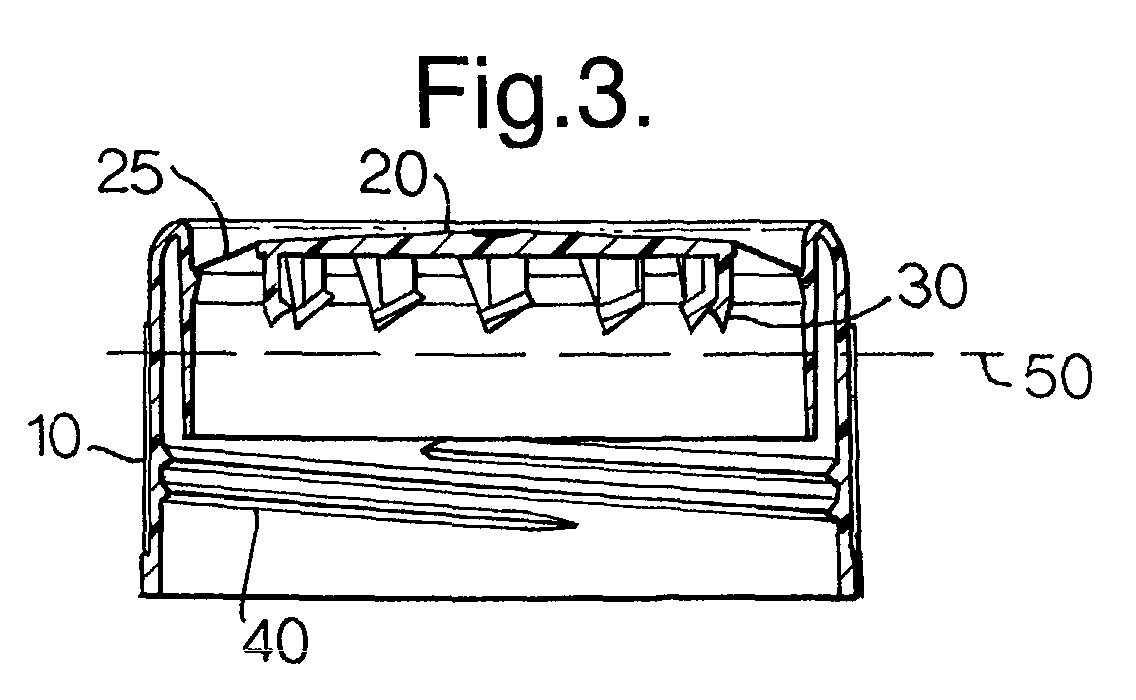
- a plurality (in this case twelve) of downwardly depending opening elements generally indicated 30 When viewed in the cross section of Fig.3 the opening elements 30 are shown to be teeth-like projections.
- a screw thread 40 is provided at the lower end of the annular skirt 10 on the interior surface to allow for engagement with a container (not shown).
- the annular band 25 is upwardly inclined and as such holds the plate 20 in a first, raised position.
- a notional plane indicated 50 which is defined by the level of the laminar closure (not shown) when the closure is secured to the container. It will be noted that in the first position of the panel 20 the opening elements are held spaced from the plane 50.
- Figs. 4 and 5 the panel 20 is shown in a second position in which the opening elements 30 now extend below the level of the plane 50.
- the panel 20 is shown in a second position and the annular band 25 is shown in a downwardly inclined state. Movement of the panel 20 from the first position shown in Fig. 3 to the second position shown in Fig.4 is achieved by a downward pressure on the panel 20 member which causes movement of the annular band 25 from its upwardly inclined to its downwardly inclined orientation.
- the first and second positions of the plate 20 are stable positions and the positions intermediate the two are unstable such that movement between the first and second positions is a snap action which provides the force for the opening element to extend below the level of the laminar closure member as described in more detail below.
- the raised and lowered positions of the plate 20 are visually distinguishable; this serves as a tamper-evident feature.
- the plate 20 may be prevented from returning to the first position or there may be provided a frangibly detachable element to prevent re-setting of the closure with no evidence on the closure itself that the plate 20 has been activated to open the container.
- Each opening element 30 includes a generally rectangular body 60.
- a generally triangular piercing portion 65 extends from a lower edge of the body 60;
- a generally triangular cutting portion 70 extends from a side edge of the body 60.
- the position of the plane 50 with the opening elements in their lowered positions as shown in Fig.4 illustrates that in the lowered position the panel 20 has allowed piercing through the laminar closure member and positioned the cutting portion transverse the plane 50 such that rotary motion of the closure with respect to the container will now provide the force for the cutting member to cut through the laminar closure member.
- a retaining portion 75 extends from one side of the body to lie substantially in line with the part of the cutting portion at which it intersects.
- the retaining portion is a generally planar projection which extends transversely to the body. It can be seen that the leading edge 80 of the retaining portion 75 is slightly below the plane 50. As the container and the plastics closure are rotated relative to each other the cutting portion 70 cuts through the laminar closure member which is then lifted by the inclined retaining portion 75.
- the laminar closure member panel When the plastics closure is rotated with respect to the container the laminar closure member panel will therefore be separated from the remainder of the container. Moreover the laminar closure member panel will be held collectively by the retaining portions 75 on the underside of the closure 1. When the plastics closure is further unscrewed and removed from the container the laminar closure member panel is removed with it and can therefore be easily removed from the plastics closure if required prior to screwing the closure back on to the container.
Landscapes
- Engineering & Computer Science (AREA)
- Mechanical Engineering (AREA)
- Closures For Containers (AREA)
- Devices For Opening Bottles Or Cans (AREA)
Abstract
Description
- The present invention relates generally to a plastics closure for a container of the type having a laminar closure member such as a thin severable membrane defining and sealing an opening, and to such a plastics closure in which means for opening the container are provided on the closure itself. The present invention is concerned more particularly with a plastics closure in which rotation with respect to the container is used to effect at least partial separation of the laminar closure member from the remainder of the container.
- An example of this type of closure system is a cylindrical container closed at one end to define a base and sealed at its other end by a laminar closure member, for example a panel of aluminium foil or the like. In the past, opening means for separating the panel from the remainder of the container have been conveniently provided on the plastics closure itself. For example, it is known from US Patent No. 6039198 to provide a cutting or piercing means on a plastics closure.
- If any such system is to be successful it is preferable for the separation of the laminar closure member from the remainder of the container to be as simple as possible. It is also noted by the inventor that removal of the laminar closure member from the container is an important step. If the severed panel of the laminar closure member is simply pushed into the interior of the container or not completely separated this could hinder access to the contents of the container and the user may not wish to risk contamination of the contents of the container by introduction of the severed panel.
- In many prior art plastics closures of this general type cutting means or piercing means have been provided on an upper surface of the plastics closures. For example, many tubes are sealed with a foil panel which is pierced using a barb or the like provided on an upper surface of the closures. When opening is desired the closure is removed from the container to expose the foil panel and inverted before piercing through the panel.
- In the present invention the opening means may be provided on any suitable part of the closure, for example on an upper surface so that the closure is inverted before opening takes place. However, it is preferable for the opening means to be provided on the interior of the closure so that they are not exposed to the atmosphere before they enter the container during opening and so that a normal unscrewing motion can be used to cut the foil. Where this is the case it is clear that the opening means must be spaced from the laminar closure member during transport and storage and be selectively engageable to effect opening.
- Accordingly there is provided a plastics closure for a container of the type having an opening sealed by a laminar closure member. The closure end plate carries one or a plurality of opening elements having piercing means for piercing through the laminar closure member and cutting means for cutting through the laminar closure member as the plastics closure is rotated with respect to the container; the opening elements further include retaining means for lifting and retaining the laminar closure member panel during or following cutting. The closure is characterised in that the end plate is movable from a stable raised position to a stable lowered position with respect to the laminar closure member to effect piercing.
- The opening elements are thereby movable between a raised, retracted position and a lowered, extended position. In the raised position the opening elements are held above the laminar closure member and in the lowered position at least part of the opening means are held below the member as far as is required to effect piercing and allow subsequent cutting, lifting and retaining of the closure member as the plastics closure is rotated relative to the container.
- It is therefore a feature of the present invention that both the separation and removal steps are performed by the plastics closure itself and, moreover, are performed using only the rotation of the closure with respect to the container.
- The presence of the retaining means simplifies the opening of the container, and has the additional benefit of removal of the laminar closure member with no additional input required from the user.
- The end plate may be surrounded by an annular band which is movable between upwardly and downwardly inclined stable positions to allow the end plate to be moved between the raised and lowered positions.
- The end plate may be rigid; this allows force to be applied directly to the panel which then transfers the force to the opening elements.
- A snap action arrangement for the end plate is preferred. This means that the force required to move the plate completely from its raised to its lowered position must be overcome before the plate moves. This is particularly useful for situations where the laminar closure member is formed from material which is likely to stretch when pressure is applied by a piercing tool. A sharp stabbing movement from a piercing tool is more likely to pierce into the material cleanly. A further advantage of this push-button type arrangement is that it requires movement only from the end plate and not from the whole of the closure.
- During the movement of the opening elements from the raised to the lowered position of the end plate they are preferably substantially perpendicular to the laminar closure member at least at the point of contact, as this is ideal for piercing. In the case of a flat rigid end plate the teeth would therefore be positioned perpendicular to the panel and the movement of the plate would be perpendicular to the laminar closure member. Inclination away from the perpendicular might, however, be used to give other benefits such as better retention of the cut laminar panel. A flexible domed end plate would change the inclination of the teeth as it moved and so would require appropriate initial inclination to ensure perpendicularlity at contact.
- In a preferred embodiment the opening elements comprise one or a plurality of teeth-like projections.
- The piercing means, the cutting means and the retaining means may all be formed on the or the same opening element. In this case all of the elements can be identical to simplify production. Whilst the principle of the present invention is applicable to all containers of this general type a preferred embodiment uses screw thread engagement to secure the cap to the container. Of course other such systems, for example, snap-fit engagement could be equally well applied.
- Where a plurality of opening elements are present they may be disposed around or adjacent the periphery of the closure end plate. This maximises the size of the aperture created from the size of the closure. Of course the elements could be disposed a distance in from the periphery, which would result in a smaller laminar closure member panel being removed. In practice the positioning of the elements will be dictated by the required aperture size and the size of the closure end plate.
- The retaining means may comprise an inclined surface extending upwardly away from a leading edge which is below the plane of the laminar closure member when the opening means are in the lowered position, to lift and retain the laminar closure member in the plastics closure as it is rotated.
- The opening means may be formed as an integral part of the closure although of course it will be understood that they might also be formed as a separate and removable element which can be attached prior to opening of the container.
- Externally obvious visual evidence that the container has been opened is an advantage in such systems. Because the end plate is moved from a raised to a lower position the distinction between the raised and lowered positions provides a tamper-evident feature. There may be further provided a tamper-evident band frangibly detachable from the plastics closure when it is removed from the container, activated to indicate that the opening means have been used.
- The present invention will now be more particularly described, by way of example, with reference to the accompanying drawings, in which:
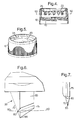
- Fig.1 is a perspective view of a plastics closure according to the present invention;
- Fig.2 is an under plan view of the closure of Fig.1;
- Fig.3 is a cross section of the closure of Fig.2 taken along line III-III;
- Fig.4 is a magnified side view of an opening element provided on the plastics closure of Fig.3;
- Fig.5 is a frontal view of the opening element shown in Fig.4;
- Fig.6 is a perspective view of the closure of Fig.1 with the opening means shown in a lowered position; and
- Fig.7 is a cross section taken along line VII-VII of Fig.2 when the opening means are in the lowered position.
-
- Referring first to Fig.1 there is shown a plastics closure generally indicated 1 comprising an
annular skirt 10 closed at one end by acircular end plate 20 that is joined to theskirt 10 by anannular band 25. - Referring now also to Fig.2, mutually spaced around the periphery of the inner surface of the
panel 20 are a plurality (in this case twelve) of downwardly depending opening elements generally indicated 30. When viewed in the cross section of Fig.3 theopening elements 30 are shown to be teeth-like projections. As can be seen ascrew thread 40 is provided at the lower end of theannular skirt 10 on the interior surface to allow for engagement with a container (not shown). As can be seen from Figs. 1 and 3 theannular band 25 is upwardly inclined and as such holds theplate 20 in a first, raised position. - Also shown in Fig.3 is a notional plane indicated 50 which is defined by the level of the laminar closure (not shown) when the closure is secured to the container. It will be noted that in the first position of the
panel 20 the opening elements are held spaced from theplane 50. - Referring now to Figs. 4 and 5 the
panel 20 is shown in a second position in which theopening elements 30 now extend below the level of theplane 50. Thepanel 20 is shown in a second position and theannular band 25 is shown in a downwardly inclined state. Movement of thepanel 20 from the first position shown in Fig. 3 to the second position shown in Fig.4 is achieved by a downward pressure on thepanel 20 member which causes movement of theannular band 25 from its upwardly inclined to its downwardly inclined orientation. The first and second positions of theplate 20 are stable positions and the positions intermediate the two are unstable such that movement between the first and second positions is a snap action which provides the force for the opening element to extend below the level of the laminar closure member as described in more detail below. The raised and lowered positions of theplate 20 are visually distinguishable; this serves as a tamper-evident feature. In some embodiments (not shown) theplate 20 may be prevented from returning to the first position or there may be provided a frangibly detachable element to prevent re-setting of the closure with no evidence on the closure itself that theplate 20 has been activated to open the container. - Referring now to Figs. 6 and 7, an
opening element 30 is shown in more detail. Each openingelement 30 includes a generallyrectangular body 60. A generally triangular piercingportion 65 extends from a lower edge of thebody 60; a generallytriangular cutting portion 70 extends from a side edge of thebody 60. The position of theplane 50 with the opening elements in their lowered positions as shown in Fig.4 illustrates that in the lowered position thepanel 20 has allowed piercing through the laminar closure member and positioned the cutting portion transverse theplane 50 such that rotary motion of the closure with respect to the container will now provide the force for the cutting member to cut through the laminar closure member. - In addition a retaining
portion 75 extends from one side of the body to lie substantially in line with the part of the cutting portion at which it intersects. The retaining portion is a generally planar projection which extends transversely to the body. It can be seen that the leadingedge 80 of the retainingportion 75 is slightly below theplane 50. As the container and the plastics closure are rotated relative to each other the cuttingportion 70 cuts through the laminar closure member which is then lifted by the inclined retainingportion 75. - When the plastics closure is rotated with respect to the container the laminar closure member panel will therefore be separated from the remainder of the container. Moreover the laminar closure member panel will be held collectively by the retaining
portions 75 on the underside of the closure 1. When the plastics closure is further unscrewed and removed from the container the laminar closure member panel is removed with it and can therefore be easily removed from the plastics closure if required prior to screwing the closure back on to the container.
Claims (10)
- A plastics closure (1) for a container of the type having an opening sealed by a laminar closure member,
the closure end plate (20)carries one or a plurality of opening elements (30) having piercing means (65) for piercing through the laminar closure member and cutting means (70) for cutting through the laminar closure member as the plastics closure is rotated with respect to the container, the opening elements further include retaining means (75) for lifting and retaining the laminar closure member panel during or following cutting,
characterised in that the end plate (20) is movable from a stable raised position to a stable lowered position with respect to the laminar closure member to effect piercing. - A closure according to Claim 1, wherein the end plate (20) is rigid and is attached to the closure side skirt (10) by a band (25) which is movable between upwardly and downwardly inclined positions to allow the end plate to be moved between the raised and lowered positions.
- A closure according to Claim 1 or Claim 2, wherein the opening elements (30) are disposed around the periphery of the end plate (20).
- A closure according to any of Claims 1 to 3, wherein the end plate (20) is substantially flat.
- A closure according to any preceding claim, wherein the movement of the end plate (20) is a snap action.
- A closure according to any preceding claim, wherein the opening elements (30) are substantially perpendicular to the laminar closure member at the point of contact between the piercing means and the member.
- A closure according to any preceding claim, wherein the opening elements (30) are substantially perpendicular to the end plate (20).
- A closure according to any preceding claim, wherein the movement of the end plate (20) is substantially perpendicular to the laminar closure member.
- A plastics closure according to any preceding claim, wherein the retaining means (75) comprise an inclined surface extending upwardly away from a leading edge (80) which is below the plane of the laminar closure member when the end plate (20) is in the lowered position whereby to lift and retain the laminar closure member panel in the closure as it is rotated.
- A plastics closure according to any preceding claim, wherein the piercing means (65), the cutting means (70) and the retaining means (75) are formed on the same opening element (30).
Priority Applications (1)
| Application Number | Priority Date | Filing Date | Title |
|---|---|---|---|
| EP02251141A EP1234778B1 (en) | 2001-02-22 | 2002-02-20 | Pierce and cut closure |
Applications Claiming Priority (3)
| Application Number | Priority Date | Filing Date | Title |
|---|---|---|---|
| EP01301637 | 2001-02-22 | ||
| EP01301637 | 2001-02-22 | ||
| EP02251141A EP1234778B1 (en) | 2001-02-22 | 2002-02-20 | Pierce and cut closure |
Publications (2)
| Publication Number | Publication Date |
|---|---|
| EP1234778A1 true EP1234778A1 (en) | 2002-08-28 |
| EP1234778B1 EP1234778B1 (en) | 2005-05-04 |
Family
ID=34560144
Family Applications (1)
| Application Number | Title | Priority Date | Filing Date |
|---|---|---|---|
| EP02251141A Expired - Lifetime EP1234778B1 (en) | 2001-02-22 | 2002-02-20 | Pierce and cut closure |
Country Status (4)
| Country | Link |
|---|---|
| EP (1) | EP1234778B1 (en) |
| AT (1) | ATE294749T1 (en) |
| DE (1) | DE60203952T2 (en) |
| ES (1) | ES2239204T3 (en) |
Cited By (6)
| Publication number | Priority date | Publication date | Assignee | Title |
|---|---|---|---|---|
| JP2007528324A (en) * | 2003-02-14 | 2007-10-11 | クウォン リョ,ヒー | Container stopper with push-type opening device |
| US20090301988A1 (en) * | 2004-12-09 | 2009-12-10 | Hee Kwon Rho | Vessel cap and system for manufacturing the same |
| WO2011151611A1 (en) | 2010-06-04 | 2011-12-08 | Obrist Closures Switzerland Gmbh | Self- piercing closure with a self-closing valve |
| EP1863724A4 (en) * | 2005-03-15 | 2013-03-27 | Hee Kwon Rho | Child-resistant cap |
| CN114919861A (en) * | 2021-02-11 | 2022-08-19 | 格雷斯海姆玻璃有限公司 | Support member for supporting seal of container |
| WO2023173042A1 (en) | 2022-03-09 | 2023-09-14 | Country Enterprises, Inc. | Foil cutter |
Families Citing this family (1)
| Publication number | Priority date | Publication date | Assignee | Title |
|---|---|---|---|---|
| KR20060099794A (en) * | 2005-03-15 | 2006-09-20 | 노희권 | Child protection cap |
Citations (8)
| Publication number | Priority date | Publication date | Assignee | Title |
|---|---|---|---|---|
| US4185756A (en) * | 1977-11-28 | 1980-01-29 | American Flange & Manufacturing Co. | Dispensing package and method |
| EP0411384A1 (en) * | 1989-08-03 | 1991-02-06 | Abbott Laboratories | Piercing closure |
| US5082136A (en) * | 1991-02-06 | 1992-01-21 | Enviro-Packaging Corp. | Container and cap construction |
| FR2730703A1 (en) * | 1995-02-17 | 1996-08-23 | Manufacturas Inplast Sa | Flexible stopper for bottles with laminated seal |
| GB2305655A (en) * | 1995-09-27 | 1997-04-16 | Francis Clark | Device or closure for cutting a container seal membrane |
| WO1997016355A1 (en) * | 1995-11-03 | 1997-05-09 | Valent U.S.A. Corporation | Method and apparatus for removing a container closure |
| EP0937653A1 (en) * | 1998-02-24 | 1999-08-25 | Novembal | Closing device for an opening of a container |
| US6039198A (en) * | 1998-11-24 | 2000-03-21 | Owens-Illinois Closure Inc. | Pierce and cut closure |
-
2002
- 2002-02-20 AT AT02251141T patent/ATE294749T1/en not_active IP Right Cessation
- 2002-02-20 ES ES02251141T patent/ES2239204T3/en not_active Expired - Lifetime
- 2002-02-20 DE DE60203952T patent/DE60203952T2/en not_active Expired - Lifetime
- 2002-02-20 EP EP02251141A patent/EP1234778B1/en not_active Expired - Lifetime
Patent Citations (8)
| Publication number | Priority date | Publication date | Assignee | Title |
|---|---|---|---|---|
| US4185756A (en) * | 1977-11-28 | 1980-01-29 | American Flange & Manufacturing Co. | Dispensing package and method |
| EP0411384A1 (en) * | 1989-08-03 | 1991-02-06 | Abbott Laboratories | Piercing closure |
| US5082136A (en) * | 1991-02-06 | 1992-01-21 | Enviro-Packaging Corp. | Container and cap construction |
| FR2730703A1 (en) * | 1995-02-17 | 1996-08-23 | Manufacturas Inplast Sa | Flexible stopper for bottles with laminated seal |
| GB2305655A (en) * | 1995-09-27 | 1997-04-16 | Francis Clark | Device or closure for cutting a container seal membrane |
| WO1997016355A1 (en) * | 1995-11-03 | 1997-05-09 | Valent U.S.A. Corporation | Method and apparatus for removing a container closure |
| EP0937653A1 (en) * | 1998-02-24 | 1999-08-25 | Novembal | Closing device for an opening of a container |
| US6039198A (en) * | 1998-11-24 | 2000-03-21 | Owens-Illinois Closure Inc. | Pierce and cut closure |
Cited By (7)
| Publication number | Priority date | Publication date | Assignee | Title |
|---|---|---|---|---|
| JP2007528324A (en) * | 2003-02-14 | 2007-10-11 | クウォン リョ,ヒー | Container stopper with push-type opening device |
| US20090301988A1 (en) * | 2004-12-09 | 2009-12-10 | Hee Kwon Rho | Vessel cap and system for manufacturing the same |
| US8820554B2 (en) * | 2004-12-09 | 2014-09-02 | Hee Kwon Rho | Vessel cap having a cutter and hook for removing and retaining a seal |
| EP1863724A4 (en) * | 2005-03-15 | 2013-03-27 | Hee Kwon Rho | Child-resistant cap |
| WO2011151611A1 (en) | 2010-06-04 | 2011-12-08 | Obrist Closures Switzerland Gmbh | Self- piercing closure with a self-closing valve |
| CN114919861A (en) * | 2021-02-11 | 2022-08-19 | 格雷斯海姆玻璃有限公司 | Support member for supporting seal of container |
| WO2023173042A1 (en) | 2022-03-09 | 2023-09-14 | Country Enterprises, Inc. | Foil cutter |
Also Published As
| Publication number | Publication date |
|---|---|
| ES2239204T3 (en) | 2005-09-16 |
| EP1234778B1 (en) | 2005-05-04 |
| DE60203952D1 (en) | 2005-06-09 |
| ATE294749T1 (en) | 2005-05-15 |
| DE60203952T2 (en) | 2005-09-22 |
Similar Documents
| Publication | Publication Date | Title |
|---|---|---|
| US4634013A (en) | Closing and opening device for membrane-sealed bottles | |
| KR100747092B1 (en) | Caps for containers and sealable containers | |
| EP1606185B1 (en) | Closure with push type opener | |
| US5129531A (en) | Closure assembly with breakaway tamper evident membrane | |
| US5505326A (en) | Closure device for membrane-sealed container | |
| US5090581A (en) | Bottle caps | |
| US5975369A (en) | Resealable pushable container closure and cover therefor | |
| US20040026422A1 (en) | Membrane penetrating closure with deformable top surface | |
| US7036683B2 (en) | Plastic closing device with a piercing element | |
| CN114423683B (en) | Lids for containers | |
| US20040149786A1 (en) | Closing device with a piercing element | |
| US5082136A (en) | Container and cap construction | |
| US4602718A (en) | Dual-operation tamper-evident band for closures | |
| EP2639178A2 (en) | Sealing member for container | |
| US5709311A (en) | Method and apparatus for removing and storing a container seal | |
| EP1234778B1 (en) | Pierce and cut closure | |
| US5613617A (en) | Sealed container that is easily opened and mass-produced | |
| JPH11171233A (en) | Spout for liquid container | |
| WO1993024405A1 (en) | Tool for opening a container | |
| US20040007587A1 (en) | Membrane piercing closure | |
| JPH08282710A (en) | Resealable unsealing device for container | |
| US4682701A (en) | Tamper-proof container | |
| RU2785825C1 (en) | Lid for container | |
| EP0242453A2 (en) | Metal cap with improved means for its partial or total removal, particularly for medicinal product containers | |
| RU17317U1 (en) | LIQUID VESSEL CAP |
Legal Events
| Date | Code | Title | Description |
|---|---|---|---|
| PUAI | Public reference made under article 153(3) epc to a published international application that has entered the european phase |
Free format text: ORIGINAL CODE: 0009012 |
|
| 17P | Request for examination filed |
Effective date: 20020220 |
|
| AK | Designated contracting states |
Kind code of ref document: A1 Designated state(s): AT BE CH CY DE DK ES FI FR GB GR IE IT LI LU MC NL PT SE TR |
|
| AX | Request for extension of the european patent |
Free format text: AL;LT;LV;MK;RO;SI |
|
| AKX | Designation fees paid |
Designated state(s): AT BE CH CY DE DK ES FI FR GB GR IE IT LI LU MC NL PT SE TR |
|
| 17Q | First examination report despatched |
Effective date: 20040303 |
|
| RAP1 | Party data changed (applicant data changed or rights of an application transferred) |
Owner name: CROWN PACKAGING TECHNOLOGY, INC |
|
| GRAP | Despatch of communication of intention to grant a patent |
Free format text: ORIGINAL CODE: EPIDOSNIGR1 |
|
| GRAS | Grant fee paid |
Free format text: ORIGINAL CODE: EPIDOSNIGR3 |
|
| GRAA | (expected) grant |
Free format text: ORIGINAL CODE: 0009210 |
|
| AK | Designated contracting states |
Kind code of ref document: B1 Designated state(s): AT BE CH CY DE DK ES FI FR GB GR IE IT LI LU MC NL PT SE TR |
|
| PG25 | Lapsed in a contracting state [announced via postgrant information from national office to epo] |
Ref country code: LI Free format text: LAPSE BECAUSE OF FAILURE TO SUBMIT A TRANSLATION OF THE DESCRIPTION OR TO PAY THE FEE WITHIN THE PRESCRIBED TIME-LIMIT Effective date: 20050504 Ref country code: BE Free format text: LAPSE BECAUSE OF FAILURE TO SUBMIT A TRANSLATION OF THE DESCRIPTION OR TO PAY THE FEE WITHIN THE PRESCRIBED TIME-LIMIT Effective date: 20050504 Ref country code: AT Free format text: LAPSE BECAUSE OF FAILURE TO SUBMIT A TRANSLATION OF THE DESCRIPTION OR TO PAY THE FEE WITHIN THE PRESCRIBED TIME-LIMIT Effective date: 20050504 Ref country code: FI Free format text: LAPSE BECAUSE OF FAILURE TO SUBMIT A TRANSLATION OF THE DESCRIPTION OR TO PAY THE FEE WITHIN THE PRESCRIBED TIME-LIMIT Effective date: 20050504 Ref country code: NL Free format text: LAPSE BECAUSE OF FAILURE TO SUBMIT A TRANSLATION OF THE DESCRIPTION OR TO PAY THE FEE WITHIN THE PRESCRIBED TIME-LIMIT Effective date: 20050504 Ref country code: CH Free format text: LAPSE BECAUSE OF FAILURE TO SUBMIT A TRANSLATION OF THE DESCRIPTION OR TO PAY THE FEE WITHIN THE PRESCRIBED TIME-LIMIT Effective date: 20050504 |
|
| REG | Reference to a national code |
Ref country code: GB Ref legal event code: FG4D |
|
| REG | Reference to a national code |
Ref country code: CH Ref legal event code: EP |
|
| REG | Reference to a national code |
Ref country code: IE Ref legal event code: FG4D |
|
| REF | Corresponds to: |
Ref document number: 60203952 Country of ref document: DE Date of ref document: 20050609 Kind code of ref document: P |
|
| PG25 | Lapsed in a contracting state [announced via postgrant information from national office to epo] |
Ref country code: SE Free format text: LAPSE BECAUSE OF FAILURE TO SUBMIT A TRANSLATION OF THE DESCRIPTION OR TO PAY THE FEE WITHIN THE PRESCRIBED TIME-LIMIT Effective date: 20050804 Ref country code: GR Free format text: LAPSE BECAUSE OF FAILURE TO SUBMIT A TRANSLATION OF THE DESCRIPTION OR TO PAY THE FEE WITHIN THE PRESCRIBED TIME-LIMIT Effective date: 20050804 Ref country code: DK Free format text: LAPSE BECAUSE OF FAILURE TO SUBMIT A TRANSLATION OF THE DESCRIPTION OR TO PAY THE FEE WITHIN THE PRESCRIBED TIME-LIMIT Effective date: 20050804 |
|
| REG | Reference to a national code |
Ref country code: ES Ref legal event code: FG2A Ref document number: 2239204 Country of ref document: ES Kind code of ref document: T3 |
|
| PG25 | Lapsed in a contracting state [announced via postgrant information from national office to epo] |
Ref country code: PT Free format text: LAPSE BECAUSE OF FAILURE TO SUBMIT A TRANSLATION OF THE DESCRIPTION OR TO PAY THE FEE WITHIN THE PRESCRIBED TIME-LIMIT Effective date: 20051017 |
|
| NLV1 | Nl: lapsed or annulled due to failure to fulfill the requirements of art. 29p and 29m of the patents act | ||
| REG | Reference to a national code |
Ref country code: CH Ref legal event code: PL |
|
| PG25 | Lapsed in a contracting state [announced via postgrant information from national office to epo] |
Ref country code: IE Free format text: LAPSE BECAUSE OF NON-PAYMENT OF DUE FEES Effective date: 20060220 |
|
| PG25 | Lapsed in a contracting state [announced via postgrant information from national office to epo] |
Ref country code: LU Free format text: LAPSE BECAUSE OF NON-PAYMENT OF DUE FEES Effective date: 20060228 Ref country code: MC Free format text: LAPSE BECAUSE OF NON-PAYMENT OF DUE FEES Effective date: 20060228 |
|
| PLBE | No opposition filed within time limit |
Free format text: ORIGINAL CODE: 0009261 |
|
| STAA | Information on the status of an ep patent application or granted ep patent |
Free format text: STATUS: NO OPPOSITION FILED WITHIN TIME LIMIT |
|
| ET | Fr: translation filed | ||
| 26N | No opposition filed |
Effective date: 20060207 |
|
| REG | Reference to a national code |
Ref country code: GB Ref legal event code: 732E |
|
| REG | Reference to a national code |
Ref country code: IE Ref legal event code: MM4A |
|
| REG | Reference to a national code |
Ref country code: FR Ref legal event code: CD Ref country code: FR Ref legal event code: TP |
|
| PG25 | Lapsed in a contracting state [announced via postgrant information from national office to epo] |
Ref country code: TR Free format text: LAPSE BECAUSE OF FAILURE TO SUBMIT A TRANSLATION OF THE DESCRIPTION OR TO PAY THE FEE WITHIN THE PRESCRIBED TIME-LIMIT Effective date: 20050504 |
|
| PG25 | Lapsed in a contracting state [announced via postgrant information from national office to epo] |
Ref country code: CY Free format text: LAPSE BECAUSE OF FAILURE TO SUBMIT A TRANSLATION OF THE DESCRIPTION OR TO PAY THE FEE WITHIN THE PRESCRIBED TIME-LIMIT Effective date: 20050504 |
|
| PGFP | Annual fee paid to national office [announced via postgrant information from national office to epo] |
Ref country code: IT Payment date: 20120228 Year of fee payment: 11 |
|
| PGFP | Annual fee paid to national office [announced via postgrant information from national office to epo] |
Ref country code: DE Payment date: 20130219 Year of fee payment: 12 Ref country code: FR Payment date: 20130301 Year of fee payment: 12 Ref country code: GB Payment date: 20130218 Year of fee payment: 12 |
|
| PG25 | Lapsed in a contracting state [announced via postgrant information from national office to epo] |
Ref country code: IT Free format text: LAPSE BECAUSE OF NON-PAYMENT OF DUE FEES Effective date: 20130220 |
|
| REG | Reference to a national code |
Ref country code: DE Ref legal event code: R119 Ref document number: 60203952 Country of ref document: DE |
|
| GBPC | Gb: european patent ceased through non-payment of renewal fee |
Effective date: 20140220 |
|
| REG | Reference to a national code |
Ref country code: FR Ref legal event code: ST Effective date: 20141031 |
|
| REG | Reference to a national code |
Ref country code: DE Ref legal event code: R119 Ref document number: 60203952 Country of ref document: DE Effective date: 20140902 |
|
| PG25 | Lapsed in a contracting state [announced via postgrant information from national office to epo] |
Ref country code: FR Free format text: LAPSE BECAUSE OF NON-PAYMENT OF DUE FEES Effective date: 20140228 Ref country code: GB Free format text: LAPSE BECAUSE OF NON-PAYMENT OF DUE FEES Effective date: 20140220 Ref country code: DE Free format text: LAPSE BECAUSE OF NON-PAYMENT OF DUE FEES Effective date: 20140902 |
|
| PGFP | Annual fee paid to national office [announced via postgrant information from national office to epo] |
Ref country code: ES Payment date: 20170213 Year of fee payment: 16 |
|
| REG | Reference to a national code |
Ref country code: ES Ref legal event code: FD2A Effective date: 20190801 |
|
| PG25 | Lapsed in a contracting state [announced via postgrant information from national office to epo] |
Ref country code: ES Free format text: LAPSE BECAUSE OF NON-PAYMENT OF DUE FEES Effective date: 20180221 |