EP1234710A1 - Electric machine, electric machine system - Google Patents
Electric machine, electric machine system Download PDFInfo
- Publication number
- EP1234710A1 EP1234710A1 EP00966438A EP00966438A EP1234710A1 EP 1234710 A1 EP1234710 A1 EP 1234710A1 EP 00966438 A EP00966438 A EP 00966438A EP 00966438 A EP00966438 A EP 00966438A EP 1234710 A1 EP1234710 A1 EP 1234710A1
- Authority
- EP
- European Patent Office
- Prior art keywords
- portable device
- electric
- power supply
- electric device
- portable
- Prior art date
- Legal status (The legal status is an assumption and is not a legal conclusion. Google has not performed a legal analysis and makes no representation as to the accuracy of the status listed.)
- Withdrawn
Links
Images


Classifications
-
- B—PERFORMING OPERATIONS; TRANSPORTING
- B60—VEHICLES IN GENERAL
- B60L—PROPULSION OF ELECTRICALLY-PROPELLED VEHICLES; SUPPLYING ELECTRIC POWER FOR AUXILIARY EQUIPMENT OF ELECTRICALLY-PROPELLED VEHICLES; ELECTRODYNAMIC BRAKE SYSTEMS FOR VEHICLES IN GENERAL; MAGNETIC SUSPENSION OR LEVITATION FOR VEHICLES; MONITORING OPERATING VARIABLES OF ELECTRICALLY-PROPELLED VEHICLES; ELECTRIC SAFETY DEVICES FOR ELECTRICALLY-PROPELLED VEHICLES
- B60L1/00—Supplying electric power to auxiliary equipment of vehicles
-
- B—PERFORMING OPERATIONS; TRANSPORTING
- B60—VEHICLES IN GENERAL
- B60L—PROPULSION OF ELECTRICALLY-PROPELLED VEHICLES; SUPPLYING ELECTRIC POWER FOR AUXILIARY EQUIPMENT OF ELECTRICALLY-PROPELLED VEHICLES; ELECTRODYNAMIC BRAKE SYSTEMS FOR VEHICLES IN GENERAL; MAGNETIC SUSPENSION OR LEVITATION FOR VEHICLES; MONITORING OPERATING VARIABLES OF ELECTRICALLY-PROPELLED VEHICLES; ELECTRIC SAFETY DEVICES FOR ELECTRICALLY-PROPELLED VEHICLES
- B60L3/00—Electric devices on electrically-propelled vehicles for safety purposes; Monitoring operating variables, e.g. speed, deceleration or energy consumption
-
- B—PERFORMING OPERATIONS; TRANSPORTING
- B60—VEHICLES IN GENERAL
- B60L—PROPULSION OF ELECTRICALLY-PROPELLED VEHICLES; SUPPLYING ELECTRIC POWER FOR AUXILIARY EQUIPMENT OF ELECTRICALLY-PROPELLED VEHICLES; ELECTRODYNAMIC BRAKE SYSTEMS FOR VEHICLES IN GENERAL; MAGNETIC SUSPENSION OR LEVITATION FOR VEHICLES; MONITORING OPERATING VARIABLES OF ELECTRICALLY-PROPELLED VEHICLES; ELECTRIC SAFETY DEVICES FOR ELECTRICALLY-PROPELLED VEHICLES
- B60L58/00—Methods or circuit arrangements for monitoring or controlling batteries or fuel cells, specially adapted for electric vehicles
- B60L58/10—Methods or circuit arrangements for monitoring or controlling batteries or fuel cells, specially adapted for electric vehicles for monitoring or controlling batteries
-
- B—PERFORMING OPERATIONS; TRANSPORTING
- B60—VEHICLES IN GENERAL
- B60L—PROPULSION OF ELECTRICALLY-PROPELLED VEHICLES; SUPPLYING ELECTRIC POWER FOR AUXILIARY EQUIPMENT OF ELECTRICALLY-PROPELLED VEHICLES; ELECTRODYNAMIC BRAKE SYSTEMS FOR VEHICLES IN GENERAL; MAGNETIC SUSPENSION OR LEVITATION FOR VEHICLES; MONITORING OPERATING VARIABLES OF ELECTRICALLY-PROPELLED VEHICLES; ELECTRIC SAFETY DEVICES FOR ELECTRICALLY-PROPELLED VEHICLES
- B60L2210/00—Converter types
- B60L2210/20—AC to AC converters
-
- B—PERFORMING OPERATIONS; TRANSPORTING
- B60—VEHICLES IN GENERAL
- B60L—PROPULSION OF ELECTRICALLY-PROPELLED VEHICLES; SUPPLYING ELECTRIC POWER FOR AUXILIARY EQUIPMENT OF ELECTRICALLY-PROPELLED VEHICLES; ELECTRODYNAMIC BRAKE SYSTEMS FOR VEHICLES IN GENERAL; MAGNETIC SUSPENSION OR LEVITATION FOR VEHICLES; MONITORING OPERATING VARIABLES OF ELECTRICALLY-PROPELLED VEHICLES; ELECTRIC SAFETY DEVICES FOR ELECTRICALLY-PROPELLED VEHICLES
- B60L2270/00—Problem solutions or means not otherwise provided for
- B60L2270/30—Preventing theft during charging
- B60L2270/36—Preventing theft during charging of vehicles
-
- Y—GENERAL TAGGING OF NEW TECHNOLOGICAL DEVELOPMENTS; GENERAL TAGGING OF CROSS-SECTIONAL TECHNOLOGIES SPANNING OVER SEVERAL SECTIONS OF THE IPC; TECHNICAL SUBJECTS COVERED BY FORMER USPC CROSS-REFERENCE ART COLLECTIONS [XRACs] AND DIGESTS
- Y02—TECHNOLOGIES OR APPLICATIONS FOR MITIGATION OR ADAPTATION AGAINST CLIMATE CHANGE
- Y02T—CLIMATE CHANGE MITIGATION TECHNOLOGIES RELATED TO TRANSPORTATION
- Y02T10/00—Road transport of goods or passengers
- Y02T10/60—Other road transportation technologies with climate change mitigation effect
- Y02T10/70—Energy storage systems for electromobility, e.g. batteries
-
- Y—GENERAL TAGGING OF NEW TECHNOLOGICAL DEVELOPMENTS; GENERAL TAGGING OF CROSS-SECTIONAL TECHNOLOGIES SPANNING OVER SEVERAL SECTIONS OF THE IPC; TECHNICAL SUBJECTS COVERED BY FORMER USPC CROSS-REFERENCE ART COLLECTIONS [XRACs] AND DIGESTS
- Y02—TECHNOLOGIES OR APPLICATIONS FOR MITIGATION OR ADAPTATION AGAINST CLIMATE CHANGE
- Y02T—CLIMATE CHANGE MITIGATION TECHNOLOGIES RELATED TO TRANSPORTATION
- Y02T10/00—Road transport of goods or passengers
- Y02T10/60—Other road transportation technologies with climate change mitigation effect
- Y02T10/72—Electric energy management in electromobility
-
- Y—GENERAL TAGGING OF NEW TECHNOLOGICAL DEVELOPMENTS; GENERAL TAGGING OF CROSS-SECTIONAL TECHNOLOGIES SPANNING OVER SEVERAL SECTIONS OF THE IPC; TECHNICAL SUBJECTS COVERED BY FORMER USPC CROSS-REFERENCE ART COLLECTIONS [XRACs] AND DIGESTS
- Y02—TECHNOLOGIES OR APPLICATIONS FOR MITIGATION OR ADAPTATION AGAINST CLIMATE CHANGE
- Y02T—CLIMATE CHANGE MITIGATION TECHNOLOGIES RELATED TO TRANSPORTATION
- Y02T90/00—Enabling technologies or technologies with a potential or indirect contribution to GHG emissions mitigation
- Y02T90/10—Technologies relating to charging of electric vehicles
- Y02T90/16—Information or communication technologies improving the operation of electric vehicles
Definitions
- the present invention relates to an electric device being a small electric mobile unit such as an electric scooter, an electric bicycle, an electric wheelchair, an electric cart, an electric walker for an aged person, or the like, which uses a relatively large secondary battery as a power source, and to an electric device system in which the electric device is connected with a portable device (a portable-type information processing device) such as a notebook personal computer or the like and supplies electric power thereto and the portable device is made usable as a display means or an inputting means.
- a portable device a portable-type information processing device
- an electric vehicle including a storage battery pack composed of a plurality of storage batteries mounted as a power source such as an electric bicycle or an electric wheel chair.
- a storage battery pack composed of a plurality of storage batteries mounted as a power source such as an electric bicycle or an electric wheel chair.
- electric vehicles of this type some run only by a driving force of a motor which is driven by electric energy (electric power) from the mounted storage battery pack, some run by a resultant force of a driving force of a motor and human power, some switch and use a driving force of a gasoline engine and a driving force of a motor, and the like.
- these portable devices have display ability capable of sufficiently displaying a speedometer, a tachometer, a fuel gauge, an odometer (an integrating traveling distance meter), a tripmeter (an integrating traveling distance meter with a reset function), and so on, necessary in an instrument panel of the electric vehicle.
- a conventional four-wheeled vehicle such as a gasoline-powered vehicle, a vehicle driven by combination of gasoline and a battery, an electric vehicle, or the like
- the vehicle has a power supply such as a rather large battery or power generator for the performance of the vehicle, or a large number of electronic devices already exist in a car. Therefore, the power supply is taken outside as a power source for the aforesaid portable devices, which has facilitated the supply of electric power to the portable devices.
- the present invention provides an electric device and an electric device system configured as follows:
- An electric device has a power supply including a rechargeable secondary battery, an electric motor operated by electric power supplied from the power supply, a driver for driving the electric motor, and a controller for monitoring, managing, and controlling the driver and the whole device.
- the electric device is characterized by comprising: a portable device power supply to which a portable device is connectable and which supplies electric power to the connected portable device; and a key switch having a first switch interposed in a main power line for supplying electric power from the power supply to the controller and the driver, and a second switch interposed in a power line for supplying electric power from the power supply to the portable device power supply, in which the first switch is turned on at a second key position and the second switch is turned on at a first key position and the second key position.
- the electric device is characterized by comprising: a portable device power supply to which a portable device is connectable and which supplies to the connected portable device electric power supplied from the power supply; and a portable device interface means for communicating information with the connected portable device.
- an electric device system is constituted by the aforesaid electric device and a portable device having a display and connected to the portable device power supply for communicating information with the electric device via the portable device interface means, and is characterized in that display information of the electric device is displayed on the portable device.
- the electric device system may be constituted by the aforesaid electric device, and a portable device for communicating information with the electric device via the portable device interface means, connected to the portable device power supply, wherein the portable device is provided with means for sending out ID data of a program operating therein to the electric device, and the electric device is provided with means for determining authorization/prohibition of operation of the electric device based on the ID data received from the portable device.
- the portable device is provided with means for sending out an inputted password to the electric device, and the electric device is provided with means for determining authorization/prohibition of operation of the electric device based on the password received from the portable device.
- the portable device is provided with means for sending out ID data of a program operating therein to the electric device and means for sending out an inputted password to the electric device, and the electric device is provided with means for determining authorization/prohibition of operation of the electric device based on the ID data and the password received from the portable device.
- the electric device is provided with a switch for controlling a supply of electric power from the power supply to the portable device power supply, and means for enabling electric power supply from the portable device power supply by turning on the switch when at least one of the ID data and the password received from the portable device matches a previously registered ID data or password.
- the portable device is provided with means for sending out inputted operation mode specification information to the electric device
- the electric device is provided with means for controlling the operation of the electric device and/or operation of the portable device power supply in accordance with the operation mode specification information from the portable device.
- the power supply in these electric devices or electric device systems is a power supply comprising a rechargeable battery unit constituted by paring a storage battery pack being the secondary battery and a memory for storing at least information on charge and discharge states of the storage battery pack.
- FIG. 1 is a block diagram showing a configuration of a first embodiment of an electric device according to the invention, in which a secondary battery such as a storage battery pack or the like is employed as a power supply to enable a supply of sufficient power to a portable device, and a display section of the portable device is made usable also as a display means of the electric device.
- a secondary battery such as a storage battery pack or the like
- a display section of the portable device is made usable also as a display means of the electric device.
- An electric device 1 is constituted by a configuration mainly including a power supply 2, a controller 3 for controlling each section of the electric device 1, a driver 4, an electric motor 5, a key switch 6, a portable device power supply 7, a portable device power line 8, an instrument panel 9, and so on.
- the key switch 6 interlocks with a first switch SW1 and a second switch SW2 at two stages which are switched by inserting a key into a key hole and turning it, and a lock mechanism for an operating system including a steering wheel and the like which operates at a position where the key can be pulled out (a turning range with hatching in FIG. 1).
- the power supply 2 is constituted by a rechargeable secondary battery such as a lead storage battery, a Ni-Cd storage battery, a Ni-MH storage battery, a lithium ion storage battery, or the like, and supplies electric power necessary for operating the electric device.
- a rechargeable secondary battery such as a lead storage battery, a Ni-Cd storage battery, a Ni-MH storage battery, a lithium ion storage battery, or the like.
- the first switch SW1 interlocks with the key switch 6 provided in the electric device 1 and turns on when the key switch 6 is operated to a second key position (ON2) to supply electric power of the power supply 2 to each section via a main power line 12.
- the controller 3 starts control of each section of the electric device 1 when the first switch SW1 turns on and power is supplied thereto via the main power line 12.
- the controller 3 cooperates with the driver 4 via a driver control signal line 14 to cause the electric motor 5 to operate, thereby operating the electric device 1.
- the controller 3 monitors states necessary as the electric device 1 such as a residual capacity of the secondary battery of the power supply 2, the state of the power supply 2 such as temperature and so on if necessary, the operating state of the electric motor 5, and so on, via a power supply control signal line 13, the driver control signal line 14, and the like; and displays information on the instrument panel 9 via an instrument panel I/F signal line 15, gives an alarm, and so on, in order to communicate necessary information to the user. Accordingly, the controller 3 monitors, manages, and controls the whole electric device 1.
- the driver 4 receives the instruction from the controller 3 via the driver control signal line 14 to operate the electric device 1 and communicates information required by the controller 3 such as the number of rotation of the electric motor 5 or not shown wheels of the electric device 1, the temperature of the electric motor 5, and the like, via the driver control signal line 14.
- the electric motor 5 is a power source driven by the driver 4 to rotate the wheels so as to cause the electric device 1 to run.
- the portable device power supply 7 receives a supply of electric power from the power supply 2 when the key switch 6 is operated to a first key position (ON1) or the second key position (ON2) to turn on the second switch SW2, and supplies electric power necessary for a portable device 10 via the portable device power line 8.
- the type of electric power supplied shall be a type required by the portable device 10, for example, direct current electric power by a DC/DC converter, or electric power of a commercial power supply by a DC/AC inverter (AC100 V in Japan).
- a power outlet of the portable device power supply 7 is desirably provided in a helmet case that does not require a special device for holding the portable device 10.
- the key switch 6 can be removed in a range of a LOCK position shown with hatching in FIG. 1. In this event, the operation of the electric device 1 is in a stop state, where all the operating system including the steering wheel and the like is locked. However, when the key is pulled out at the first key position ON1 within the LOCK position, the second switch SW2 turns on while the electric device 1 is kept locked to allow electric power to be supplied to the portable device power supply 7, which makes it possible to supply electric power to the portable device 10.
- the provision of the first key position ON1 of the key switch 6 within the range of the LOCK position enables the key. to be pulled out at the first key position ON1, which makes it impossible for the electric device 1 to operate. This makes it possible to prevent theft as well as to maintain the supply of electric power to the portable device 10 to enable use of the portable device 10 such as a notebook personal computer or the like even in that state.
- the lock of the operating system including the steering wheel and the like is released, and the first switch SW1 turns on.
- This allows electric power to be supplied from the power supply 2 to the controller 3 and the driver 4 via the main power line 12 to bring the electric device 1 into a state capable of operating, and the electric power is also supplied to the portable device power supply 7 to maintain the supply of electric power to the portable device 10.
- the controller 3 supplied with electric power starts control of the operation of the electric device 1 and cooperates with the driver 4 to operate the electric motor 5 when an instruction for operation is given by the user, although not shown in the drawing, thereby causing the electric device 1 to run.
- the controller 3 monitors states necessary as the electric device 1, that is, monitors a residual capacity of the secondary battery of the power supply 2, the state of the power supply 2 such as temperature and so on if necessary, via the power supply control signal line 13, also monitors the operating state of the electric motor 5 via the driver control signal line 14, and so on; and performs a display for communicating to the user information necessary for the user on the instrument panel 9 via the instrument panel I/F signal line 15, gives an alarm, and so on.
- the controller 3 has a function of monitoring, managing, and controlling the whole electric device 1.
- FIG. 2 is a block diagram showing a configuration of the second embodiment of the electric device, in which the same sections as those in FIG. 1 are assigned the same numerals and symbols.
- the second embodiment differs from the first embodiment in that as for a key switch 6', while the key switch 6 in the first embodiment is a two-stage switch which turns on the second switch SW2 at the first key position ON1 and turns on both of the first switch SW1 and second switch SW2 at the second key position SW2, the key switch 6' in the second embodiment only turns on a switch SW at an ON position and turns off the switch SW at an OFF (LOCK) position to activate a lock mechanism of an operating system. Therefore, there is no switch corresponding to the second switch SW2 shown in FIG. 1.
- a portable device interface means (hereinafter, abbreviated to a "portable device I/F means") 16 and a portable device I/F signal line 17 are provided.
- the other configuration is common with the electric device of the first embodiment shown in FIG. 1, and thus the description thereof is omitted.
- the switch SW turns on when the key switch 6' provided in the electric device 1 is turned to the ON position by the key inserted into the key hole to allow electric power of the power supply 2 to be supplied to each section via a main power line 12.
- a portable device power supply 7 receives a supply of electric power from the power supply 2 when the switch SW is turned on by the key switch 6' to supply electric power required by a portable device 10 via a portable device power line 8.
- the type of electric power supplied shall be direct current electric power or electric power of the commercial power required by the portable device 10.
- the portable device I/F means 16 receives information required by a user from the controller 3 via the instrument panel I/F signal line 15, converts it into a signal appropriate for the portable device 10, and sends it out to the portable device 10 via the portable device I/F signal line 17.
- the portable device 10 such as a notebook personal computer or the like connected to the portable device power line 8 receives the signal from the portable device I/F signal line 17, the portable device 10 displays it on its own display section (a liquid crystal display or the like).
- the portable device I/F means 16 receives via the portable device I/F signal line 17 information from the portable device 10, for example, password information for authorization to operate the electric device 1, the portable device I/F means 16 communicates it to the controller 3 via the instrument panel I/F signal line 15.
- a serial I/F (interface) shown in FIG. 3 which is typically installed in a palmtop personal computer, a notebook personal computer, and the like, or an IrDA of infrared data communication as shown in FIG. 4 is employed, which allows the portable device I/F signal line 17 to provide for many types of devices.
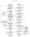
- FIG. 5 a flow of the operation of the electric device 1 in this case is shown on the left-hand side, a flow of the operation of the portable device 10 is shown on the right-hand side, and fold lines with arrows show mutual relationship therebetween.
- the switch SW is turned on by the key switch 6 of the electric device 1 to allow electric power of the power supply 2 to be supplied via the main power line 12 to each necessary section of the electric device 1, which enables operation thereof.
- FIG. 5 shows a flowchart of the electric device 1 from the power thereof being turned on by the key switch until it becomes a state capable of operating, and communication of the electric device with the portable device 10 in operation.
- the controller 3 sends out an ID request command to the portable device via the instrument panel I/F signal line 15, the portable device I/F means 16, and the portable device I/F signal line 17 in step A1, and waits for a response from the portable device 10 in step A2.
- the ID is not an ID of the portable device 10 itself but shall be an ID of a program operating in the portable device 10, which eliminates limitation of portable devices.
- the portable device 10 is waiting for the ID request command from the electric device 1 in step B1, and when the portable device 10 receives the ID request command from the electric device 1, it proceeds to step B2 and sends out ID data to the electric device in response to the request.
- the electric device 1 receives the ID data sent out from the portable device 10 and verifies whether or not it is a correct ID which is registered in advance, returns to step A1 when it is different from the ID, and proceeds to step A3 when it is correct.
- step A3 the electric device 1 sends out a password request command for making a request to the user for a password for authorizing operation of the electric device 1 via the portable device 10, and waits for the password in step A4.
- the portable device 10 returns to step B2 and sends out the ID data until the password request command is sent in step B3, and when the portable device 10 receives the password request command in step B3, it proceeds to step B4.
- step B4 the portable device 10 performs a display of requesting the user to input a password, and waits for input of a password in step B5. Any method may be employed for display contents and inputting a password if it is suitable for properties of the portable device.
- the portable device 10 returns to step B4 and maintains the display of requesting input of a password until input of a password is finished in step B5, and proceeds to step B6 when the input of the password is finished.
- step B6 the portable device 10 stores the inputted password in a predetermined location by a predetermined method and sends out the password to the electric device.
- the electric device 1 waits for the password being sent in step A4, and when receiving the password from the portable device 10, the electric device 1 compares it with the previously registered password, proceeds to step A5 when they match, and returns to step A3 when they do not match.
- step A5 the controller 3 authorizes the operation of the electric device 1 by a predetermined method, and the electric device 1 proceeds to step A6.
- step A6 the electric device 1 sends out to the portable device 10 display information obtained by combining operation authorization information and information required to be displayed on the portable device as the electric device, and proceeds to step A7.
- display information parity and/or a checksum or the like are/is added to provide for discrimination of the information between correct and incorrect.
- the portable device 10 checks the display information received from the electric device 1 in step B7, proceeds to step B8 when it is correct, and proceeds to step B11 when it is incorrect.
- step B8 the portable device 10 sends out a predetermined password to the electric device 1, and proceeds to step B9.
- the electric device 1 is waiting for the password as a response to sending of the display information, in step A7.
- the electric device 1 verifies the password and returns to step A6 when it is correct, and the state of the electric device 1 authorized to operate is maintained.
- the electric device 1 proceeds to step A8.
- step A8 the electric device 1 checks a series of errors of passwords, and proceeds to step A9 when the number of errors reaches a predetermined number. When the number of errors does not reach the predetermined number, the electric device 1 returns to step A6.
- step A9 the controller 3 brings the electric device 1 into a state of being prohibited to operate, and the electric device 1 returns to step A6.
- the display information sent out in step A6 changes from operation authorization to operation prohibition. It is conceivable that there are other elements to prohibit operation of the electric device, but the description thereof is not made because the elements are inherent in electric devices and can not be defined and they are not directly related to the invention.
- the portable device 10 proceeds to step B10 when the information received in step B9 is correct, and returns to step B7 when it is incorrect to maintain the preceding display.
- step B10 the portable device 10 processes the display information and displays it, and returns to step B7.
- step B11 the portable device 10 manages incorrect display information there, proceeds to step B12 when a predetermined number of abnormalities continues, and returns to step B8 when the number of abnormalities does not reach the predetermined number.
- step B12 the portable device 10 rewrites abnormal data (data differing from the password) over the password stored in the predetermined location, and proceeds step B13.
- the portable device 10 displays the abnormality, and thereafter returns to step B8 and sends out the password.
- the abnormality occurring in the display system is also detected on the electric device 1 side, so that the electric device 1 is brought into a state of being prohibited to operate.
- the reason why the abnormality is displayed in step B13 is to report the abnormality to the user. Further, if the portable device 10 is provided with a function of generating a sound, it may generate an alarm. It is also preferable that when the portable device 10 receives operation prohibition information from the electric device 1, it may similarly generate an alarm.
- connection of the portable device 10 to the electric device 1 becomes a second key, and further the password becomes a third key, which makes it possible to improve the prevention of unauthorized use and theft.
- the operation can be realized by omitting steps A3 and A4 on the electric device 1 side and steps B3, B4, B5 and B6 on the portable device 10 side and replacing "password" with "ID data” in other steps in the flowchart shown in FIG. 5.
- steps A1 and A2 on the electric device 1 side and steps B1 and B2 on the portable device 10 side in the flowchart shown in FIG. 5 should be omitted.
- the portable device 10 can not operate because of lack of battery capacity, it is possible to hold the system as well as to charge the battery of the portable device 10 by supplying electric power from the portable device power supply 7 to the portable device 10 via the portable device power line 8.
- FIG. 6 is a block diagram showing a configuration of the electric device, in which the same sections as those in FIG. 1 and FIG. 2 are assigned the same numerals and symbols.
- An electric device 1 of the third embodiment differs from that of the second embodiment shown in FIG. 2 only in that a switch SW3, which is ON/OFF controlled by a switch control signal S3 from a controller 3, is provided between a main power line 12 extending from a power supply 2 via a switch SW and a portable device power supply 7.
- the switch SW is first turned on by operating a key switch 6' to allow electric power of the power supply 2 to be supplied to necessary sections of the electric device 1 via the main power line 12, which makes the electric device 1 capable of operating.
- the switch SW3 is controlled by the switch control signal S3 from the controller 3 and turns on to allow electric power from the power supply 2 to be supplied to the portable device power supply 7.
- the controller 3 When the switch SW turns on and electric power is supplied from the power supply 2, the controller 3 starts control of operation of the electric device 1. Further, the controller 3 has, in addition to the same function as that of the controller 3 of the second embodiment, a function of controlling opening/closing of the switch SW3 by the switch control signal S3 to control the supply of electric power to the portable device power supply 7.
- FIG. 7 shows a flowchart of the electric device from the power thereof being turned on by the key switch until it becomes a state capable of operating, and communication of the electric device with the portable device in operation. It should be noted that steps B1 to B13 of the operation of the portable device on the right-hand side are the same as steps B1 to B13 of the operation of the portable device in the flowchart shown in FIG. 5, and thus the description thereof is omitted.
- the electric device 1 starts operation when the switch SW turns on by operating the key switch 6' and electric power is supplied to the controller 3.
- step C1 the electric device 1 first turns on the switch SW3 by the switch control signal to cause the portable device power supply 7 to operate for the case of a battery of a portable device 10 being uncharged, and proceeds to step C2.
- step C2 the electric device 1 sets a portable device power supply timer, and proceeds to step C3.
- the portable device power supply timer is a timer for specifying a period of operation of the portable device power supply to prevent power supply (charge) to the portable device 10 only by application of power caused by the key switch 6' and to reduce unnecessary power consumption.
- step C3 the controller 3 sends out an ID request command to the portable device 10 via an instrument panel I/F signal line 15, a portable device I/F means 16, and a portable device I/F signal line 17, and waits for a response from the portable device 10 in step C4.
- the portable device 10 sends out ID data in step B2, and when receiving the ID data, the electric device 1 verifies whether or not it is a previously registered ID in step C4.
- the electric device 1 proceeds to step C12 when it is different from the registered ID, and proceeds to step C5 when it is correct.
- step C5 the electric device 1 sends out a password request command for making a request to the user for a password for authorizing operation of the electric device 1 via the portable device, and waits for reception of the password in step C6.
- the electric device 1 When receiving the password from the portable device 10, the electric device 1 compares it with a previously registered password in step C6. When they match, the electric device 1 determines that the correct password has been sent from the portable device and proceeds to step C7, and when they do not match, it proceeds to step C14.
- step C7 the controller 3 authorizes the operation of the electric device 1 by a predetermined method, and the electric device 1 proceeds to step C8.
- step C8 the electric device 1 sends out to the portable device display information obtained by combining operation authorization information and information required to be displayed on the portable device as the electric device, and proceeds to step C9.
- step C9 To this display information, parity and/or a checksum or the like are/is added to provide for discrimination of the information between correct and incorrect.
- step C9 the electric device 1 is waiting for a password from the portable device 10 as a response to sending of the display information.
- the electric device 1 determines whether or not it is the correct password and returns to step C8 when it is correct, and the state of the electric device 1 authorized to operate is maintained.
- the electric device 1 proceeds to step C10.
- step C10 the electric device 1 checks a series of errors of passwords, and proceeds to step C11 when the number of errors reaches a predetermined number. When the number of errors does not reach the predetermined number, the electric device 1 returns to step C8.
- step C11 the controller 3 brings the electric device 1 into a state of being prohibited to operate, and the electric device 1 returns to step C8.
- the display information sent out in step C8 changes from operation authorization to operation prohibition.
- the electric device 1 checks the portable device power supply timer, proceeds to step C13 when the specified period has elapsed, and returns to step C3 when the specified period has not elapsed.
- step C13 the controller 3 turns off the switch SW3 by the switch control signal S3 to stop the operation of the portable device I/F means 16, and returns to step C3.
- the electric device 1 checks the portable device power supply timer, proceeds to step C15 when the specified period has elapsed, and returns to step C5 when the specified period has not elapsed.
- step C15 the controller 3 turns off the switch SW3 by the switch control signal S3 to stop the operation of the portable device I/F means 16 and returns to step C5.
- steps C5, C6, C14 and C15 on the electric device 1 side and steps B3, B4, B5 and B6 on the portable device 10 side in the flowchart of FIG. 7 should be omitted, and "password" should be replaced with "ID data”.
- steps C3, C4, C12 and C13 on the electric device 1 side and steps B1 and B2 on the portable device 10 side in the flowchart of FIG. 7 should be omitted.
- FIG. 8 is a block diagram showing a configuration of the electric device, in which the same sections as those in FIG. 1, FIG. 2 and FIG. 6 are assigned the same numerals and symbols, and the description thereof is omitted.
- An electric device 1 of the fourth embodiment differs from that of the second embodiment shown in FIG. 2 only in that the key switch 6' is not provided and a switch SWa is interposed between a power supply 2 and a main power line 12 and a switch SWb is interposed between the power supply 2 and a portable device power supply 7, respectively, such that the switch SWa and the switch SWb are ON/OFF controlled by a switch control signal Sa and a switch control signal Sb from a controller 3, respectively.
- the controller 3 is supplied with electric power at all times from the power supply 2 via a power supply control signal line 13, and periodically operates the portable device power supply 7 by the switch control signal Sb as well as verifies the presence or absence of connection of a portable device 10 using a portable device I/F means 16 via an instrument panel I/F signal line 15.
- the controller 3 recognizes the connection of the portable device 10, and proceeds with processing for operation of the electric device 1.
- FIG. 9 shows the flowchart of the electric device from periodical checks on connection of the portable device by the electric device until it becomes a state capable of operating, and communication of the electric device with the portable device in operation.
- steps C5 to C14 of the operation of the electric device 1 on the left-hand side are the same as steps C5 to C14 of the operation of the electric device in the flowchart shown in FIG. 7, and steps B 1 to B 13 of the operation of the portable device on the right-hand side are the same as steps B 1 to B13 of the operation of the portable device in the flowchart shown in FIG. 7, and thus the description thereof is omitted.
- step C21 the electric device 1 turns on the switch SWb by the switch control signal Sb to cause the portable device powerosupply 7 to operate for the case of a battery of the portable device 10 being uncharged, and proceeds to step C22.
- step C22 the controller 3 sends out an ID request command to the portable device 10 via the instrument panel I/F signal line 15, the portable device I/F means 16, and a portable device I/F signal line 17, and waits for a response from the portable device 10 in step C23.
- the electric device 1 When receiving ID data from the portable device 10, the electric device 1 checks whether or not it is a correct ID matching a previously registered ID in step C23. The electric device 1 proceeds to step C24 when it is correct, and proceeds to step C25 when it is incorrect.
- step C25 the electric device 1 turns off the switch SWb in step C25, thereafter waits only for a predetermined period in step C26, and returns to step C21.
- step C24 the electric device 1 sets a portable device power supply timer for specifying a period of operation of the portable device power supply to prevent power supply (charge) to the portable device, and proceeds to step C5.
- steps C5, C6, C14 and C15 on the electric device side and steps B3 to B6 on the portable device 10 side in the flowchart of FIG. 9 should be omitted, and "password" should be replaced with "ID data”.
- steps C22, C23, C25 and C26 on the electric device side and steps B1 and B2 on the portable device 10 side in the flowchart of FIG. 9 should be omitted.
- step C21 in FIG. 9 the switch SWb is unconditionally turned on by the switch control signal Sb to cause the portable device power supply 7 to operate for the case of the battery of the portable device 10 being uncharged.
- the switch SWb is turned on to cause the portable device power supply 7 to operate so as to enable the supply of electric power to the portable device 10.
- FIG. 10 shows a flow of specification of authorization/prohibition of the operation of the electric device 1 and operation mode specification of operation/non-operation of the portable device power supply 7 by operation from the portable device 10 after the state in which the operation of the electric device 1 is authorized.
- any method is adoptable if it is suitable for properties of the portable device, such as operation of a specific key, input of commands, or the like.
- step M1 Processing in each step in FIG. 10 is explained here. First of all, a display of specifying an operation mode is performed in accordance with operation mode specification by a user in step M1, and the processing proceeds to step M2.
- step M2 specified contents by the user are judged, and when it is authorization of the electric device 1, the processing proceeds to step M3 and otherwise the processing proceeds to step M6.
- step M3 whether or not the portable device power supply 7 is ON is determined, and when it is OFF (non-operation), the processing proceeds to step M5, and when it is ON (operation), the processing proceeds to step M4.
- step M4 authorization of operation of the electric device 1 and operation of the portable device power supply 7 are specified, and the processing proceeds to step M9.
- step M5 authorization of operation of the electric device 1 and non-operation of the portable device power supply 7 are specified, and the processing proceeds to step M9.
- step M6 whether or not the portable device power supply 7 is ON is determined, and when it is ON (operation), the processing proceeds to step M7, and when it is OFF (non-operation), the processing proceeds to step M8.
- step M7 prohibition of operation of the electric device 1 and operation of the portable device power supply 7 are specified, and the processing proceeds to step M9.
- step M8 prohibition of operation of the electric device 1 and non-operation of the portable device power supply 7 are specified, and the processing proceeds to step M9.
- step M9 whether or not the operation mode is ended is determined, and when it is not ended, the processing returns to step M1 and when it is ended, the processing is ended.
- a secondary battery composed of a typical storage battery pack as the power supply of the electric device in a small mobile unit.
- a rechargeable secondary battery constituted by paring a secondary battery composed of a storage battery pack and a memory for storing at least information about charge and discharge states of the storage battery pack.
- FIG. 11 is a block circuit diagram showing a configuration example of the power supply.
- the power supply 2 is constituted by battery units 21, 22 and 23, a controlling power supply 29, a controller 28, a charger unit 30 including a charger 27, and so on.
- Storage battery packs 21B, 22B and 23B may include various types of secondary batteries such as a nickel-cadmium battery and a nickel-metal hydride battery. Further, each of memories 24, 25 and 26 is a nonvolatile memory such as an EEPROM, a flash ROM, a RAM backed up by a battery or the like, into which various kinds of information can be written which includes at least the information about charge and discharge states of the associated storage battery pack by the charger or the controller 28 provided in the power supply 2.
- the charge and discharge states of the storage battery packs 21B, 22B and 23B included therein can be recognized precisely by referring to the information stored in the memories 24, 25 and 26 even when they are mounted on the electric device 1 or they are detached therefrom to be in a single state, and thus appropriate charge and discharge controls can be conducted all the time.
- the power supply 2 of this embodiment has the plurality of battery units 21, 22 and 23 and the common charger unit 30 for charging the respective storage battery packs 21B, 22B and 23B, which are detachably mounted on the electric device main body, respectively.
- the battery units 21, 22 and 23, having the same structure, are units in which the storage battery packs 21B, 22B and 23B are paired for integration with the memories 24, 25 and 26 such as EEPROMs or the like.
- the battery units 21, 22 and 23 and battery unit installation sections (not shown) of the above-described power supply 2 provided in the electric device 1 are provided respectively with connectors Ba1, Ba2 and Ba3, connectors Bb1, Bb2 and Bb3, and connectors Bc1, Bc2 and Bc3, each of which is composed of paired terminals, as means for electrically connecting and disconnecting the battery units 21, 22 and 23 to/from the main body side of the power supply 2 incident to attachment and detachment of the battery units 21, 22 and 23, respectively.
- the charger unit 30 is a unit containing therein the charger 27 having a microcomputer and switches SW21, SW22 and SW23 corresponding to the battery units 21, 22 and 23, and is provided with connectors Cp1, Cp2, Cp3, Cg1, Cg2, Cg3, Cs1, Cs2 and Cs3, each of which is composed of paired terminals, between the charger unit 30 and the charger unit installation sections (not shown) of the power supply 2, as connecting means for electrically connecting and disconnecting the charger unit 30 to/from the main body side of the power supply 2 incident to attachment and detachment of the charger unit 30.
- the connectors Cs1, Cs2 and Cs3 of the charger unit 30 and the connectors Ba3, Bb3 and Bc3 of the battery units 21, 22 and 23 are connected to each other respectively, that is, the connectors Cs1 and Ba3, the connectors Cs2 and Bb3, and the connectors Cs3 and Bc3, by bus lines for writing and reading to/from the memories 24, 25 and 26, and further connected to the controller 28.
- the power supply 2 is provided with, on the main body side, the controller 28 for controlling the operation of the whole power supply 2, the main power line 12 for supplying electric power to each section of the electric device 1 via the controlling power supply 29 connected to the controller 28 and the above-described switch SW and so on, and three switches SW11, SW12 and SW13 interposed in discharge (feed) lines from the battery units 21, 22 and 23 to the controller 28 and the main power line 12.
- the charger 27 in the charger unit 30 has a function of charge controlling the storage battery packs 21B, 22B and 23B of the battery units 21, 22 and 23, and a function of reading and writing information from/into the memories 24, 25 and 26.
- controller 28 similarly has therein a function of reading and writing information from/into the memories 24, 25 and 26 of the battery units 21, 22 and 23 in addition to a function of controlling the whole power supply 2.
- the charger 27 receives a supply of alternating-current power from a commercial power supply 100, rectifies and smoothes it to thereby make it direct current, converting it to an output voltage suitable for charge. Further, the charger 27 reads and temporarily stores the information about the charge and discharge states of the storage battery packs 21B, 22B and 23B from the memories 24, 25 and 26 of the plurality of the mounted battery units 21, 22 and 23, and selectively turns on one of the switches SW21, SW22 and SW23 by a SW2n control signal to charge the storage battery pack of the battery unit selected based on the information. Thereby, the storage battery pack of the battery unit connected via the switch turned on is charged.
- FIG. 11 shows an example in which three battery units are mounted, but the object of the invention can be achieved by mounting at least one battery unit.
- the charger unit 30 is also detachably mounted on the main body of the power supply 2, so that it can easily be detached from the electric device 1 and used outside the electric device 1, but it may be provided fixedly to the main body of the power supply 2 provided in the electric device 1.
- Each of the storage battery packs 21B, 22B and 23B of the battery units 21, 22 and 23 is constituted by connecting in series a plurality of rechargeable storage batteries or secondary batteries.
- each of the memories 24, 25 and 26 of the battery units 21, 22 and 23 information specific to a battery such as a rated capacity, temperature characteristics, preservation characteristics and the like, and information about the charge and discharge states of the battery such as an amount of charge, an amount of discharge, the numbers of charges and discharges and the like of each of the storage battery packs 21B, 22B and 23B, are stored.
- the battery units 21, 22 and 23 have individual information respectively, which allows the plurality of the battery units 21, 22 and 23 to be attached and detached in any order.
- the switches SW11, SW12 and SW13 which are provided along respective feed lines between the battery units 21, 22 and 23, and, the controller 28 and the main power line 12, are selectively turned on by an SW1n control signal outputted based on the controlling function of the controller 28, thereby selecting which battery unit is used to feed power to the controller 28 and the main power line 12.
- the controller 28 having a microcomputer therein, detects installation states of the plurality of the battery units 21, 22 and 23 by the controlling function in conjunction with the reading/writing function, reads and temporarily stores the information stored in the memories 24, 25 and 26 therein, selects based on the information a battery unit to be discharged, and controls its discharging current and discharging voltage, to thereby conduct management appropriate for the battery characteristics of the battery unit used and the characteristics of the power supply 2 when necessary.
- this controller 28 has functions of controlling ON/OFF states of the switches SW11, SW12 and SW13 and managing and controlling the whole power supply, based on the information stored in the memories 24,25 and 26 of the battery units 21, 22 and 23.
- controller 28 is also coupled to the controller 3 for controlling the whole electric device 1 shown in FIG. 1, FIG. 2, FIG. 6 and FIG. 8 via the power supply control signal line 13, so as to exchange information and a command.
- the controlling power supply 29 has a function of supplying required electric power to the controller 28 when at least one of the battery units 21, 22 and 23 is mounted on the power supply 2.
- the controlling power supply 29 is supplied with electric power also when at least one storage battery pack among the battery units is charged by the charger 27, and in this event the controlling power supply 29 operates when necessary to supply electric power to the controller 28.
- the controlling power supply 29 supplies electric power to the controller 28 until the controller 28 stops the supply of electric power to the main power line 12, writes information about charge and discharge states and the like of the storage battery packs of operating battery units among the battery units 21, 22 and 23 into the memories in the battery units, and stops the power supply 2 in safety and the like to thereby complete necessary processing.
- the electric power supplied from the power supply 2 via the main power line 12 based on the controlling function of the controller 28 is supplied to the controller 3 and the driver 4 via the switch SW1 by operation of the key switch in the first embodiment shown in FIG. 1.
- electric power is supplied to each section of the electric device 1 via the main power line 12 and also to the portable device power supply 7, which makes it possible to supply electric power to the portable device 10 connected thereto.
- the power supply 2 may comprise: a plurality of battery units detachably mounted thereon, each battery unit constituted by integrating a storage battery pack, a memory for storing at least information about charge and discharge states of the storage battery pack, and a charger for charging the storage battery pack; connectors, provided on each battery unit and a battery unit installation section on the device main body side, for performing electrical connection/disconnection to/from the device main body side incident to attachment/detachment of the battery unit; and a driver for driving a load and a controller for controlling a supply of electric power from each battery unit to the driver by referring to the information stored in the memory of each mounted battery unit, which are provided on the device main body side.
- the provision of a portable device power supply in an electric device enables supply (charge) of electric power to a portable device even in a small electric device.
- the portable device connected via a portable device I/F signal line can also be used as a display device of the electric device.
- an ID of the portable device or its operation program is sent/received to/from the electric device, so as to prevent unauthorized use and/or theft.
Landscapes
- Engineering & Computer Science (AREA)
- Power Engineering (AREA)
- Transportation (AREA)
- Mechanical Engineering (AREA)
- Life Sciences & Earth Sciences (AREA)
- Sustainable Development (AREA)
- Sustainable Energy (AREA)
- Lock And Its Accessories (AREA)
- Electric Propulsion And Braking For Vehicles (AREA)
- Charge And Discharge Circuits For Batteries Or The Like (AREA)
- Mobile Radio Communication Systems (AREA)
- Remote Monitoring And Control Of Power-Distribution Networks (AREA)
Abstract
Description
Claims (12)
- An electric device having a power supply including a rechargeable secondary battery, an electric motor operated by electric power supplied from said power supply, a driver for driving said electric motor, and a controller for monitoring, managing, and controlling said driver and said whole device, comprising:a portable device power supply to which a portable device is connectable and which supplies electric power to said connected portable device; anda key switch having a first switch interposed in a main power line for supplying electric power from said power supply to said controller and said driver, and a second switch interposed in a power line for supplying electric power from said power supply to said portable device power supply, in which said first switch is turned on at a second key position and said second switch is turned on at a first key position and said second key position.
- An electric device having a power supply including a rechargeable secondary battery, an electric motor operated by electric power supplied from said power supply, a driver for driving said electric motor, and a controller for monitoring, managing, and controlling said driver and said whole device, comprising:a portable device power supply to which a portable device is connectable and which supplies to said connected portable device electric power supplied from said power supply; anda portable device interface means for communicating information with said connected portable device.
- An electric device system constituted by the electric device according to claim 2 and a portable device, having a display and connected to said portable device power supply, for communicating information with said electric device via said portable device interface means,
wherein display information of said electric device is displayed on said portable device. - An electric device system constituted by the electric device according to claim 2 and a portable device connected to said portable device power supply for communicating information with said electric device via said portable device interface means,
wherein said portable device is provided with means for sending out ID data of a program operating therein to said electric device, and
wherein said electric device is provided with means for determining authorization/prohibition of operation of said electric device based on the ID data received from said portable device. - An electric device system constituted by the electric device according to claim 2 and a portable device connected to said portable device power supply for communicating information with said electric device via said portable device interface means,
wherein said portable device is provided with means for sending out an inputted password to said electric device, and
wherein said electric device is provided with means for determining authorization/prohibition of operation of said electric device based on the password received from said portable device. - An electric device system constituted by the electric device according to claim 2 and a portable device connected to said portable device power supply for communicating information with said electric device via said portable device interface means,
wherein said portable device is provided with means for sending out ID data of a program operating therein to said electric device and means for sending out an inputted password to said electric device, and
wherein said electric device is provided with means for determining authorization/prohibition of operation of said electric device based on the ID data and the password received from said portable device. - The electric device system according to claim 6,
wherein said electric device is provided with a switch for controlling a supply of electric power from said power supply to said portable device power supply, and means for enabling electric power supply from said portable device power supply by turning on said switch when at least one of the ID data and the password received from said portable device matches a previously registered ID data or password. - The electric device system according to any one of claim 3 to claim 7,
wherein said portable device is provided with means for sending out inputted operation mode specification information to said electric device, and
wherein said electric device is provided with means for controlling the operation of said electric device and/or operation of said portable device power supply in accordance with the operation mode specification information from said portable device. - The electric device according to claim 1,
wherein said power supply comprises a rechargeable battery unit constituted by paring a storage battery pack being said secondary battery and a memory for storing at least information on charge and discharge states of said storage battery pack. - The electric device according to claim 2,
wherein said power supply comprises a rechargeable battery unit constituted by paring a storage battery pack being said secondary battery and a memory for storing at least information on charge and discharge states of said storage battery pack. - The electric device system according to any one of claim 3 to claim 7,
wherein said power supply of said electric device comprises a rechargeable battery unit constituted by paring a storage battery pack being said secondary battery and a memory for storing at least information on charge and discharge states of said storage battery pack. - The electric device system according to claim 8,
wherein said power supply of said electric device comprises a rechargeable battery unit constituted by paring a storage battery pack being said secondary battery and a memory for storing at least information on charge and discharge states of said storage battery pack.
Priority Applications (1)
| Application Number | Priority Date | Filing Date | Title |
|---|---|---|---|
| EP20060024628 EP1764255A1 (en) | 1999-11-22 | 2000-10-12 | Electric device and electric device system |
Applications Claiming Priority (3)
| Application Number | Priority Date | Filing Date | Title |
|---|---|---|---|
| JP33210699 | 1999-11-22 | ||
| JP33210699A JP4090166B2 (en) | 1999-11-22 | 1999-11-22 | Electric device and electric device system |
| PCT/JP2000/007079 WO2001038122A1 (en) | 1999-11-22 | 2000-10-12 | Electric machine, electric machine system |
Related Child Applications (1)
| Application Number | Title | Priority Date | Filing Date |
|---|---|---|---|
| EP20060024628 Division EP1764255A1 (en) | 1999-11-22 | 2000-10-12 | Electric device and electric device system |
Publications (2)
| Publication Number | Publication Date |
|---|---|
| EP1234710A1 true EP1234710A1 (en) | 2002-08-28 |
| EP1234710A4 EP1234710A4 (en) | 2003-05-21 |
Family
ID=18251226
Family Applications (2)
| Application Number | Title | Priority Date | Filing Date |
|---|---|---|---|
| EP00966438A Withdrawn EP1234710A4 (en) | 1999-11-22 | 2000-10-12 | Electric machine, electric machine system |
| EP20060024628 Withdrawn EP1764255A1 (en) | 1999-11-22 | 2000-10-12 | Electric device and electric device system |
Family Applications After (1)
| Application Number | Title | Priority Date | Filing Date |
|---|---|---|---|
| EP20060024628 Withdrawn EP1764255A1 (en) | 1999-11-22 | 2000-10-12 | Electric device and electric device system |
Country Status (7)
| Country | Link |
|---|---|
| US (1) | US6762572B1 (en) |
| EP (2) | EP1234710A4 (en) |
| JP (1) | JP4090166B2 (en) |
| KR (1) | KR100464710B1 (en) |
| CN (1) | CN1224536C (en) |
| CA (1) | CA2392179C (en) |
| WO (1) | WO2001038122A1 (en) |
Cited By (1)
| Publication number | Priority date | Publication date | Assignee | Title |
|---|---|---|---|---|
| CN110298939A (en) * | 2018-03-22 | 2019-10-01 | 施耐德电器工业公司 | It locks the method for the function of electrical equipment and implements the electrical equipment of this method |
Families Citing this family (16)
| Publication number | Priority date | Publication date | Assignee | Title |
|---|---|---|---|---|
| JP4099039B2 (en) * | 2002-11-15 | 2008-06-11 | 松下電器産業株式会社 | Program update method |
| DE10344361A1 (en) * | 2003-09-24 | 2005-04-28 | Siemens Ag | Appliance for communication with installation, e.g. for operation and monitoring of automating installation in industrial manufacture, containing mobile communication apparatus for wireless data exchange with installation, etc. |
| US7636030B2 (en) * | 2005-10-26 | 2009-12-22 | Rockwell Automation Technologies, Inc. | Security layers for wireless industrial control user interface |
| US20140299392A9 (en) * | 2007-10-26 | 2014-10-09 | Frederick William Klatt | Brushless Multiphase Self-Commutation Control (BMSCC) And Related Inventions |
| US8269452B2 (en) | 2008-07-04 | 2012-09-18 | Yazaki Corporation | Battery charge monitoring device |
| TWM374434U (en) * | 2009-08-25 | 2010-02-21 | Wen-Qin Cai | Structural improvement for the electric powered bicycle |
| US9592742B1 (en) * | 2014-04-09 | 2017-03-14 | FreeWire Technologies, Inc. | Systems, apparatus, and methods of charging electric vehicles |
| JP6670547B2 (en) * | 2015-03-12 | 2020-03-25 | 株式会社 ミックウェア | Information system |
| JP6400523B2 (en) * | 2015-04-17 | 2018-10-03 | 有限会社サンビジネス | Elderly electric cart |
| US10701859B2 (en) * | 2016-01-07 | 2020-07-07 | Exmark Manufacturing Company, Incorporated | Electronic controller and turf maintenance vehicle incorporating same |
| CA3067183A1 (en) * | 2017-06-16 | 2018-12-20 | Koki Holdings Co., Ltd. | Battery pack capable of switching a connection state of a plurality of cell units and electric apparatus using battery pack |
| CN107264322A (en) * | 2017-06-29 | 2017-10-20 | 安徽先能新能源科技股份有限公司 | A kind of Portable DC charging machine |
| US11183741B2 (en) * | 2020-02-13 | 2021-11-23 | Toyota Motor Engineering & Manufacturing North America, Inc. | Battery pack assemblies having elongated terminal connectors with keyed slots |
| US11721875B2 (en) * | 2020-03-02 | 2023-08-08 | Toyota Motor Engineering & Manufacturing North America, Inc. | Battery pack assemblies having elongated terminal connectors and vehicles having the same |
| US12491958B2 (en) * | 2023-08-29 | 2025-12-09 | C-Tech United Corporation | Auxiliary assembly for bicycle |
| WO2026004546A1 (en) * | 2024-06-26 | 2026-01-02 | 株式会社クボタ | Electric work vehicle, and system and method for controlling electric work vehicle |
Family Cites Families (9)
| Publication number | Priority date | Publication date | Assignee | Title |
|---|---|---|---|---|
| US3863209A (en) * | 1972-10-06 | 1975-01-28 | Hollins J R | Vehicle seat beltstarter motor interlock and sequential warning system |
| JPS5396117A (en) | 1977-02-02 | 1978-08-23 | Hitachi Ltd | Device for controlling electric motor vehicle |
| JPS6028434U (en) * | 1983-07-29 | 1985-02-26 | 株式会社東海理化電機製作所 | Vehicle power supply circuit |
| JP2823747B2 (en) * | 1992-08-05 | 1998-11-11 | 株式会社ピーエフユー | Vehicle-mounted driving support system |
| US5396970A (en) * | 1992-10-09 | 1995-03-14 | Tokyo R&D Co., Ltd. | Electromotive scooter |
| JP3400034B2 (en) | 1993-10-12 | 2003-04-28 | 本田技研工業株式会社 | Battery remaining capacity remote display for electric vehicles |
| DE4428368C2 (en) * | 1994-08-11 | 1997-11-27 | Deere & Co | PTO control |
| JP3472434B2 (en) | 1997-04-18 | 2003-12-02 | 日産ディーゼル工業株式会社 | Electric vehicle starting circuit |
| US5973917A (en) * | 1997-05-22 | 1999-10-26 | White; M. Gerald | Portable motor vehicle work station |
-
1999
- 1999-11-22 JP JP33210699A patent/JP4090166B2/en not_active Expired - Fee Related
-
2000
- 2000-10-12 KR KR10-2002-7006469A patent/KR100464710B1/en not_active Expired - Fee Related
- 2000-10-12 EP EP00966438A patent/EP1234710A4/en not_active Withdrawn
- 2000-10-12 CA CA002392179A patent/CA2392179C/en not_active Expired - Fee Related
- 2000-10-12 CN CNB008144680A patent/CN1224536C/en not_active Expired - Fee Related
- 2000-10-12 US US10/129,972 patent/US6762572B1/en not_active Expired - Fee Related
- 2000-10-12 EP EP20060024628 patent/EP1764255A1/en not_active Withdrawn
- 2000-10-12 WO PCT/JP2000/007079 patent/WO2001038122A1/en not_active Ceased
Cited By (2)
| Publication number | Priority date | Publication date | Assignee | Title |
|---|---|---|---|---|
| CN110298939A (en) * | 2018-03-22 | 2019-10-01 | 施耐德电器工业公司 | It locks the method for the function of electrical equipment and implements the electrical equipment of this method |
| CN110298939B (en) * | 2018-03-22 | 2023-03-10 | 施耐德电器工业公司 | Method for locking the function of an electrical device and electrical device for implementing said method |
Also Published As
| Publication number | Publication date |
|---|---|
| CN1379717A (en) | 2002-11-13 |
| CA2392179C (en) | 2005-06-28 |
| JP2001157301A (en) | 2001-06-08 |
| EP1234710A4 (en) | 2003-05-21 |
| US6762572B1 (en) | 2004-07-13 |
| KR20020059766A (en) | 2002-07-13 |
| JP4090166B2 (en) | 2008-05-28 |
| CN1224536C (en) | 2005-10-26 |
| EP1764255A1 (en) | 2007-03-21 |
| KR100464710B1 (en) | 2005-01-05 |
| WO2001038122A1 (en) | 2001-05-31 |
| CA2392179A1 (en) | 2001-05-31 |
Similar Documents
| Publication | Publication Date | Title |
|---|---|---|
| CA2392179C (en) | Electric machine, electric machine system | |
| EP1223092B1 (en) | Electric vehicle | |
| EP1223653B1 (en) | Electric device and apparatus for charging battery unit, and method for charging and discharging | |
| US20130110340A1 (en) | Electric vehicle, charging stand, and method for charging the electric vehicle | |
| US9407104B2 (en) | Battery powered charger | |
| EP1462299B1 (en) | Battery power source apparatus of electric car and its method of operation | |
| JP5261838B2 (en) | Electric vehicle control device | |
| JP6569446B2 (en) | Battery control device | |
| KR101689726B1 (en) | Charging system and method for electric vehicle | |
| JPH07240213A (en) | Hybrid power supply | |
| CN105917548A (en) | Hybrid vehicle with means for disconnection of a depleted auxiliary battery in order to allow for more rapid main battery charging | |
| CN114696407A (en) | Power conversion device and power transmission system | |
| JPH0865814A (en) | Electric vehicle charging control device | |
| EP1220350A1 (en) | Electric device with timer means | |
| KR20230050495A (en) | System and method for operating removable auxiliary battert of electroic vehicle | |
| TWM620320U (en) | Mobile charging equipment for electric vehicle | |
| JP4806927B2 (en) | Power supply | |
| JP5658936B2 (en) | Secondary battery pack, charger and vehicle | |
| JP7538471B2 (en) | Vehicle control device | |
| KR20150052504A (en) | Communication interface system for sharing status information of navigation, Method for providing information of charging stations using the same, and Electric vehicle having the same | |
| JP2003176748A (en) | Hybrid vehicle | |
| KR20220108332A (en) | Charging control apparatus and method of electric vehicle using remote key | |
| US20250074244A1 (en) | System and method for charging of electric mobility apparatus | |
| KR102696177B1 (en) | Integrated control device for electric kickboard using multi-core MCU | |
| KR102738060B1 (en) | Upgraded charge apparatus for vehicles that uses commercial power and batteries |
Legal Events
| Date | Code | Title | Description |
|---|---|---|---|
| PUAI | Public reference made under article 153(3) epc to a published international application that has entered the european phase |
Free format text: ORIGINAL CODE: 0009012 |
|
| 17P | Request for examination filed |
Effective date: 20020613 |
|
| AK | Designated contracting states |
Kind code of ref document: A1 Designated state(s): AT BE CH CY DE DK ES FI FR GB GR IE IT LI LU MC NL PT SE |
|
| RIN1 | Information on inventor provided before grant (corrected) |
Inventor name: ISHII, HIROSHI Inventor name: KASUGA, NOBUYUKI, TOKYO R & D CO., LTD Inventor name: AOKI, TAKASHI |
|
| RIC1 | Information provided on ipc code assigned before grant |
Ipc: 7B 60R 25/04 B Ipc: 7B 60L 1/00 A |
|
| A4 | Supplementary search report drawn up and despatched |
Effective date: 20030407 |
|
| RBV | Designated contracting states (corrected) |
Designated state(s): AT BE CH CY DE ES FR IT LI PT |
|
| 17Q | First examination report despatched |
Effective date: 20060711 |
|
| GRAP | Despatch of communication of intention to grant a patent |
Free format text: ORIGINAL CODE: EPIDOSNIGR1 |
|
| RBV | Designated contracting states (corrected) |
Designated state(s): DE ES FR IT PT |
|
| STAA | Information on the status of an ep patent application or granted ep patent |
Free format text: STATUS: THE APPLICATION IS DEEMED TO BE WITHDRAWN |
|
| 18D | Application deemed to be withdrawn |
Effective date: 20070523 |