EP1234639A2 - Contact trip adjustment for fastening tool - Google Patents
Contact trip adjustment for fastening tool Download PDFInfo
- Publication number
- EP1234639A2 EP1234639A2 EP02250631A EP02250631A EP1234639A2 EP 1234639 A2 EP1234639 A2 EP 1234639A2 EP 02250631 A EP02250631 A EP 02250631A EP 02250631 A EP02250631 A EP 02250631A EP 1234639 A2 EP1234639 A2 EP 1234639A2
- Authority
- EP
- European Patent Office
- Prior art keywords
- contact trip
- adjuster
- lower contact
- teeth
- housing
- Prior art date
- Legal status (The legal status is an assumption and is not a legal conclusion. Google has not performed a legal analysis and makes no representation as to the accuracy of the status listed.)
- Granted
Links
Images






Classifications
-
- B—PERFORMING OPERATIONS; TRANSPORTING
- B25—HAND TOOLS; PORTABLE POWER-DRIVEN TOOLS; MANIPULATORS
- B25C—HAND-HELD NAILING OR STAPLING TOOLS; MANUALLY OPERATED PORTABLE STAPLING TOOLS
- B25C1/00—Hand-held nailing tools; Nail feeding devices
- B25C1/008—Safety devices
Definitions
- the invention relates to fastening tools having contact trips and particularly to mechanisms for easily adjusting the contact trips.
- Fastening tools are used for driving nails or staples into workpieces. It is well known in the art to provide such tools with a contact trip extending downwardly from the tool for contacting the workpiece and a separate trigger activated by the user's digits. Accordingly, the tool can be "programmed” to drive a nail only when the user has pushed the tool unto the workpiece and has activated the trigger.
- Prior art solutions such as the solution shown in US Patent No. 5,219,110, include providing a contact trip having an upper contact trip, a lower contact trip, and a rotatable element therebetween. As the element is rotated, the lower contact trip moves relative to the upper contact trip, thus adjusting the contact trip length.
- an improved fastening tool includes a housing, a magazine connected to the housing for storing a fastener, a driving mechanism disposed within the housing for driving the fastener into a workpiece, a trigger assembly pivotally attached to the housing for activating the driving mechanism, the trigger assembly comprising a main trigger, pivotally attached to the housing and a supplemental trigger pivotally attached to the main trigger; and a contact trip assembly comprising an upper contact trip contacting the supplemental trigger, a lower contact trip connected to the upper contact trip, wherein the upper and lower contact trips have teeth that mesh together for locking the upper and lower contact trips.
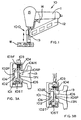
- FIG. 1 shows a fastening tool 10 comprising a main housing 15 which covers the driving mechanism (not shown) for driving a fastener, such as a nail or staple, and which includes a handle 11, a nosepiece 13 below the housing 15, a magazine 12 connected to the nosepiece 13 and the handle 11, and a trigger assembly 14 disposed on the housing 15 and/or handle 11 for activating the driving mechanism as is well known in the art.
- the driving mechanism can be a pneumatic-based system, such as the ones shown in US Patent Nos. 3,673,922 or 5,1811,450, or an electric system, such as the ones shown in US Patent No. 4,928,868. The teachings from those patents are wholly incorporated herein by reference.
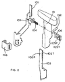
- nosepiece 13 has rods 13R (see FIG. 2) which are received within channels (not shown) in the magazine 12.
- Fastening tool 10 also comprises a first embodiment of a contact trip 100 according to the invention.
- the trigger assembly 14 may have a main trigger 14M pivotally attached to the housing 15 or handle 11 and a supplemental trigger 14S pivotally attached to the main trigger 14M.
- supplemental trigger 14S will move valve 14V, thus activating the driving mechanism.
- valve 14V will be a switch if the driving mechanism is an electric system, or an airflow-control valve if the driving mechanism is a pneumatic system.
- the operation of trigger assembly 14 in combination with contact trip assembly 100 is well known in the art, and is described in US Patent No. 5,785,228, which is wholly incorporated by reference herein.
- the contact trip assembly 100 preferably has an upper contact trip 101 for contacting supplemental trigger 14S and a lower contact trip 102 for contacting a workpiece W.
- the contact trip assembly 100 is preferably slidably attached to the housing 15 and/or nosepiece 13 so that it slides vertically when the lower contact trip 102 contacts a workpiece and the user pushes the fastening tool 10 unto the workpiece W.
- a spring 111 may be disposed between housing 15 and/or nosepiece 13 and contact trip assembly 100 to bias contact trip assembly 100 downwardly towards the workpiece W.
- Upper contact trip 101 may carry an adjuster 105.
- adjuster 105 has teeth 105T for meshing with teeth 102T disposed on lower contact trip 102. This connection may be disposed within upper contact trip 101 as shown in FIG. 3.
- Upper contact trip 101 may also carry a cover 106.
- cover 106 has hooks 106H that latch onto upper contact trip 101 in a snap-fit manner.
- Cover 106 may retain adjuster 105 therewithin.
- a button 103 is preferably disposed between upper contact trip 101 and cover 106 for moving adjuster 105.
- Button 103 may be directly connected to adjuster 105 so that they move in conjunction, e.g., a press-fit junction or a friction junction.
- button 103 may receive adjuster 105 as shown in FIG. 3A to form a mechanical connection.
- Button 103 may be kept within cover 106 by a flange 103F, which prevents button 103 from escaping.
- a spring 104 may be disposed between adjuster 105 and button 103, and received within button 103. Accordingly, the mechanical connection shown in FIG. 3A cannot be separated unless the spring 104 is separated from button 103.
- the spring 104 contacts cover 106 and biases button 103 outwardly, thus biasing adjuster 105 towards the meshing position.
- button 103 may be disposed directly on upper contact trip 101 or in any other place so long as it can move adjuster 105.
- Cover 106 may be alternatively held in place by the button/adjuster assembly. In other words, since adjuster 105 cannot escape from the upper contact trip 101, the button 103 will maintain contact with cover 106 and thus preventing cover 106 from detaching. Alternatively, cover 106 may be held in place by rivets, screws or other fastening means.
- FIG. 3A shows adjuster 105 meshing with lower contact trip 102. If the user desires to change the overall length of the contact trip assembly 100, the user would push button 103 as shown in FIG. 3B. The button 103 moves adjuster 105 until its teeth 105T do not engage with the teeth 102T of lower contact trip 102. The user can then move the lower contact trip 102 to the desired position and let go of button 103. Spring 104 will move button 103 outwardly and adjuster 105 back to the meshing position.
- teeth 105T and 102T may be inclined relative to the direction of movement of button 103, in order to increase the contact area between teeth 105T and 102T.
- the adjuster 105 could move along a direction substantially perpendicular to the direction of movement for the contact trip assembly 100, yet in a direction that is not parallel to the teeth 105T.
- adjuster 105 may be disposed on lower contact trip 102 to engage the upper contact trip 101.
- adjuster 105 may also be useful to provide adjuster 105 with a protrusion 105P that engages a notch 13N in nosepiece 13 when adjuster 105 is moved to the disengaged position. In this manner, the upper contact trip 101 cannot move upwardly and unintendedly engage the trigger assembly 14 during adjustment. Persons skilled in the art will recognize that the same result will be achieved if adjuster 105 is provided with a notch that engages a protrusion on the nosepiece.
- FIG. 23 illustrates another embodiment of the invention, where like numerals refer to like parts.
- the teachings of the previous embodiments discussed above are fully incorporated herein.
- the contact trip assembly 120 preferably has an upper contact trip 121 for contacting supplemental trigger 14S and a lower contact trip 122 for contacting a workpiece W.
- the contact trip assembly 120 is preferably slidably attached to the housing 15 and/or nosepiece 13 so that it slides vertically when the lower contact trip 122 contacts a workpiece and the user pushes the fastening tool 10 unto the workpiece W.
- a spring (not shown) may be disposed between housing 15 and/or nosepiece 13 and contact trip assembly 120 to bias contact trip assembly 120 downwardly towards the workpiece W.
- Upper contact trip 121 may carry an adjuster 125.
- adjuster 125 has teeth 125T for meshing with teeth 122T disposed on lower contact trip 122. This connection may be disposed within upper contact trip 121 as shown in FIG. 23B.
- Upper contact trip 121 may also carry a cover 123.
- cover 123 wraps around the front part of the upper contact trip 121.
- adjuster 125 extends through upper contact trip 121 and cover 123.
- FIG. 23B shows adjuster 125 meshing with lower contact trip 122. If the user desires to change the overall length of the contact trip assembly 120, the user would push adjuster 125 along direction F. The adjuster 125 would then move until its teeth 125T do not engage with the teeth 122T of lower contact trip 122. The user can then move the lower contact trip 122 to the desired position. To lock the desired position, the user would pull adjuster 125 along the direction opposite to direction F, in order to engage teeth 122T, 125T.
- Cover 123 may have a spring 123S for maintaining adjuster 125 in an engaged position and a disengaged position.
- Adjuster 125 may have notches 125D for receiving the spring 123S.
- the notches 125D and/or spring 123S may have a curved profile so that they can disengage easily upon movement of adjuster 125, rather than requiring the user to pull on the spring 123S. Accordingly, as the user pushes adjuster 125 towards the disengaged position, spring 123S pops out of notch 125D, rides along the surface of adjuster 125 and springs back into a second notch 125D, retaining the adjuster 125 in the disengaged position.
- Adjuster 125 may have a cam ramp 125C that contacts upper contact trip 121. Such cam ramp 125C is preferably arranged so that it takes up any clearance or gaps when adjuster 125 is in the engaged position.
- teeth 125T and 122T may be inclined relative to the direction of movement of adjuster 125, in order to increase the contact area between teeth 125T and 122T.
- the adjuster 125 could move along a direction substantially perpendicular to the direction of movement for the contact trip assembly 120, yet in a direction that is not parallel to the teeth 125T.
- adjuster 125 may be disposed on lower contact trip 122 to engage the upper contact trip 121.
- adjuster 125 may also be useful to provide adjuster 125 with a protrusion 125P that engages a notch 13N in nosepiece 13 when adjuster 125 is moved to the disengaged position. In this manner, the upper contact trip 121 cannot move upwardly and unintendedly engage the trigger assembly 14 during adjustment. Persons skilled in the art will recognize that the same result will be achieved if adjuster 125 is provided with a notch that engages a protrusion on the nosepiece.
- lower contact trip 122 may also be useful to provide lower contact trip 122 with a protrusion (not shown) which is received within a slot (not shown) in upper contact trip 121.
- a protrusion will slide along the slot and limit the vertical movement of lower contact trip 122 when adjuster 125 is disengaged. Accordingly, the protrusion may also prevent the lower contact trip 122 from becoming disconnected from upper contact trip 121.
- Persons skilled in the art will recognize that the same result will be achieved if lower contact trip 121 is provided with a slot that receives a protrusion on upper contact trip 121.
- a handle 125H may be attached to adjuster 125.
- Handle 125H may have notches 125N for receiving spring 123S.
- spring 123S is not integral with cover 123 in this arrangement, but captured by adjuster 125T, cover 123 and upper contact trip 121. Nevertheless, the method of operation remains the same.
- FIG. 24 illustrates another embodiment of the invention, where like numerals refer to like parts.
- the teachings of the previous embodiments discussed above are fully incorporated herein.
- the contact trip assembly 130 preferably has an upper contact trip 131 for contacting supplemental trigger 14S and a lower contact trip 132 for contacting a workpiece W.
- the contact trip assembly 130 is preferably slidably attached to the housing 15 and/or nosepiece 13 so that it slides vertically when the lower contact trip 132 contacts a workpiece and the user pushes the fastening tool 10 unto the workpiece W.
- a spring (not shown) may be disposed between housing 15 and/or nosepiece 13 and contact trip assembly 130 to bias contact trip assembly 130 downwardly towards the workpiece W.
- Upper contact trip 131 may carry an adjuster 135.
- adjuster 135 has teeth 135T for meshing with teeth 132T disposed on lower contact trip 132. This connection may be disposed within upper contact trip 131 as shown in FIG. 24.
- Adjuster 135 may be attached to a cover 135C, which covers adjuster 135 and portions of upper and lower contact trips 131, 132.
- Cover 135C may have a notch 135N that receives one end of adjuster 135.
- a pin 135P and/or grommet 136G may capture the other end of adjuster 135 within cover 135C. Accordingly, adjuster 135 and cover 135C will preferably move in unison.
- FIG. 24A shows adjuster 135 meshing with lower contact trip 132. If the user desires to change the overall length of the contact trip assembly 130, the user would push adjuster 135 (and cover 135C) along direction F. The adjuster 135 would then move until its teeth 135T do not engage with the teeth 132T of lower contact trip 132, as shown in FIG. 24B. The user can then move the lower contact trip 132 to the desired position. To lock the desired position, the user would pull adjuster 135 along the direction opposite to direction F, in order to engage teeth 132T, 135T.
- Upper contact trip 131 may also carry a spring 133S.
- spring 133S wraps around the front part of the upper contact trip 131.
- Spring 133S may be disposed between adjuster 135 and cover 135C.
- spring 133S maintains adjuster 135 in an engaged position and/or a disengaged position. Contrary to the previous embodiment, adjuster 135 does not have notches for receiving the spring 133S.
- spring 133S rests on a surface of adjuster 135. To move to the disengaged position, the user would have to move spring 133S onto teeth 135T.
- a ramp 135R is disposed on the teeth 135T to facilitate such action. Persons skilled in the art will recognize that, even with the ramp 135R, it should be difficult to move adjuster 135 unintentionally. This can be achieved by increasing spring force, increasing the ramp angle, etc.
- spring 123S rides along ramp 135R onto teeth 135T.
- the spring 133S will then rest on teeth 135T, preferably retaining the adjuster 125 in the disengaged position.
- Adjuster 135 may have a cam ramp 135CR that contacts upper contact trip 131.
- Such cam ramp 135CR is preferably arranged so that it takes up any clearance or gaps when adjuster 135 is in the engaged position.
- teeth 135T and 132T may be inclined relative to the direction of movement of adjuster 135, in order to increase the contact area between teeth 135T and 132T.
- the adjuster 135 could move along a direction substantially perpendicular to the direction of movement for the contact trip assembly 130, yet in a direction that is not parallel to the teeth 135T.
- adjuster 135 may be disposed on lower contact trip 132 to engage the upper contact trip 131.
- adjuster 135 may also be useful to provide adjuster 135 with a protrusion 135P that engages a notch 13N in nosepiece 13 when adjuster 135 is moved to the disengaged position. In this manner, the upper contact trip 131 cannot move upwardly and unintendedly engage the trigger assembly 14 during adjustment. Persons skilled in the art will recognize that the same result will be achieved if adjuster 135 is provided with a notch that engages a protrusion on the nosepiece.
- lower contact trip 132 may also be useful to provide lower contact trip 132 with a protrusion (not shown) which is received within a slot (not shown) in upper contact trip 131.
- a protrusion will slide along the slot and limit the vertical movement of lower contact trip 132 when adjuster 135 is disengaged. Accordingly, the protrusion may also prevent the lower contact trip 132 from becoming disconnected from upper contact trip 131.
- Persons skilled in the art will recognize that the same result will be achieved if lower contact trip 131 is provided with a slot that receives a protrusion on upper contact trip 131.
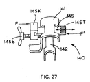
- FIG. 27 illustrates another embodiment of the invention, where like numerals refer to like parts.
- the teachings of the previous embodiments discussed above are fully incorporated herein.
- the contact trip assembly 140 preferably has an upper contact trip 141 for contacting supplemental trigger 14S and a lower contact trip 142 for contacting a workpiece W.
- the contact trip assembly 140 is preferably slidably attached to the housing 15 and/or nosepiece 13 so that it slides vertically when the lower contact trip 142 contacts a workpiece and the user pushes the fastening tool 10 unto the workpiece W.
- a spring (not shown) may be disposed between housing 15 and/or nosepiece 13 and contact trip assembly 140 to bias contact trip assembly 140 downwardly towards the workpiece W.
- Upper contact trip 141 may carry an adjuster 145.
- adjuster 145 has teeth 145T for meshing with teeth (not shown) disposed on lower contact trip 142. This connection may be disposed within upper contact trip 141.
- adjuster 145 extends through upper contact trip 141.
- Adjuster 145 may have a handle 145K for moving adjuster 145.
- Handle 145K may in turn carry a screw 145S, which may contact upper contact trip 141.
- the user would push adjuster 145 along direction F.
- the adjuster 145 would then move until its teeth 145T do not engage with the teeth of lower contact trip 142.
- the user can then move the lower contact trip 142 to the desired position.
- the user would (a) pull or push adjuster 145 along the direction F' in order to engage the teeth.
- the user may rotate screw 145S so that it contacts upper contact trip 141, and moves adjuster 145 along direction F'.
- adjuster 145 may have a cam ramp (not shown) that contacts upper contact trip 141.
- cam ramp is preferably arranged so that it takes up any clearance or gaps when adjuster 145 is in the engaged position.
- teeth 145T may be inclined relative to the direction of movement of adjuster 145, in order to increase the contact area between the teeth.
- the adjuster 145 could move along a direction substantially perpendicular to the direction of movement for the contact trip assembly 140, yet in a direction that is not parallel to the teeth 145T.
- adjuster 145 may be disposed on lower contact trip 142 to engage the upper contact trip 141.
- adjuster 145 may also be useful to provide adjuster 145 with a protrusion (not shown) that engages a notch 13N in nosepiece 13 when adjuster 145 is moved to the disengaged position. In this manner, the upper contact trip 141 cannot move upwardly and unintendedly engage the trigger assembly 14 during adjustment. Persons skilled in the art will recognize that the same result will be achieved if adjuster 145 is provided with a notch that engages a protrusion on the nosepiece.
- lower contact trip 142 may also be useful to provide lower contact trip 142 with a protrusion (not shown) which is received within a slot (not shown) in upper contact trip 141.
- a protrusion will slide along the slot and limit the vertical movement of lower contact trip 142 when adjuster 145 is disengaged. Accordingly, the protrusion may also prevent the lower contact trip 142 from becoming disconnected from upper contact trip 141.
- Persons skilled in the art will recognize that the same result will be achieved if lower contact trip 141 is provided with a slot that receives a protrusion on upper contact trip 141.
- FIGS. 4-8 illustrate another embodiment of the invention, where like numerals refer to like parts.
- the teachings of the previous embodiments discussed above are fully incorporated herein. This embodiment may be especially useful when an adjustable wireform contact trip is desirable.
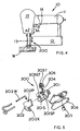
- tool 10 is provided with an adjustable contact trip assembly 200.
- the contact trip assembly 200 preferably has an upper contact trip 201 for engaging trigger assembly 14 and a lower contact trip 202 for contacting a workpiece.
- the contact trip assembly 200 is preferably slidably attached to the housing 15 and/or nosepiece 13 so that it slides vertically when the lower contact trip 202 contacts a workpiece W and the user pushes the fastening tool 10 unto the workpiece W.
- Lower contact trip 202 may include a wire 202W which contacts the workpiece as discussed above. Lower contact trip 202 is preferably disposed within upper contact trip 201.
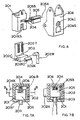
- Upper contact trip 201 may carry an adjuster 205. As shown in FIG. 8, upper contact trip 201 may have a lip 201L that is received in a slot 205SL in adjuster 205. Upper contact trip 201 and adjuster 205 may have other features, such as the lip 201L and slot 205SL, for locking the vertical position of the adjuster 205 relative to the upper contact trip 201, as shown in FIG. 8. The lip/slot combination and the other features however should allow the adjuster 205 to move towards and away the upper contact trip 201 along a horizontal axis 205A, which is preferably the longitudinal axis of adjuster 205. Persons skilled in the art will know how to design the upper contact trip 201 and adjuster 205 to achieve such result.
- adjuster 205 have teeth 205T for meshing with teeth 202T disposed on lower contact trip 202. This connection may be disposed within upper contact trip 201 as shown in FIG. 8.
- a spring 204 may be disposed between upper contact trip 201 and adjuster 205 for biasing adjuster 205 away from upper contact trip 201and preferably towards a meshing position.
- Adjuster 205 may have an inset boss 205B for receiving spring 204.
- the upper contact trip 201/lower contact trip 202 assembly may be disposed within a cover 206, which is connected to the housing 15.
- a button 203 is preferably disposed between upper contact trip 201 and cover 206 for moving adjuster 205.
- Button 203 may be directly connected to adjuster 205 so that they move in conjunction, e.g., a press-fit junction or a friction junction.
- button 203 is not mechanically connected to adjuster 205.
- Button 203 may be kept within cover 206 by a flange 203F which prevents button 203 from escaping. Because adjuster 205 contacts button 203, spring 204 in effect biases button 203 outwardly. Persons skilled in the art shall recognize that button 203 may be disposed directly on upper contact trip 201 or in any other place so long as it can move adjuster 205.
- cover 206 is connected to housing 15 via bolts 206 and stop bolt 206SB.
- FIG. 7A shows adjuster 205 meshing with lower contact trip 202. If the user desires to change the overall length of the contact trip assembly 200, the user would push button 203 as shown in FIG. 7B. The button 203 moves adjuster 205 until its teeth 205T do not engage with the teeth 202T of lower contact trip 202. The user can then move the lower contact trip 202 to the desired position and let go of button 203. Spring 204 will move button 203 and adjuster 205 outwardly back to the meshing position.
- adjuster 205 may be disposed on lower contact trip 202 to engage the upper contact trip 201.
- lower contact trip 202 may be useful to provide lower contact trip 202 with a protrusion 202P which is received within a slot 201S in upper contact trip 201.
- Such protrusion 202P will slide along the slot and limit the vertical movement of lower contact trip 202. Accordingly, the protrusion 202P may also prevent the lower contact trip 202 from becoming disconnected from upper contact trip 201.
- Persons skilled in the art will recognize that the same result will be achieved if lower contact trip 201 is provided with a slot that receives a protrusion on upper contact trip 201.
- Protrusion 201ST would limit the downward movement of contact trip 200 by contacting stop bolt 206SB when the contact trip assembly has moved to the downward limit.
- knob 202K It may also be useful to provide the lower contact trip 202 with a knob 202K.
- the user could use knob 202K to adjust lower contact trip 202 while pressing button 203.
- knob 202K can move vertically along a slot 201KS of upper contact trip 201 and slot 206S of cover 206, when lower contact trip 201 is being vertically adjusted.
- Knob 202K and cover 206 may have indicia 202KI and 206I, respectively, which indicate the relative length of the contact trip assembly 200.
- button 203 engages lip 201L when pushed towards the disengaged position. Such engagement prevents upper contact trip 201 from moving upwardly and unintendedly engaging the trigger assembly 14 during adjustment.
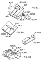
- FIGS. 15-17 illustrate other embodiments of the invention, where like numerals refer to like parts.
- the embodiment of FIGS. 15-16 is very similar to the embodiment of FIGS. 4-8, and only vary slightly. Nevertheless, the teachings of the embodiments discussed above are fully incorporated herein.
- buttons 207 are slidably attached to the adjuster 205.
- Button 207 can move axially with adjuster 205 between the engaged and disengaged positions.
- button 207 is captured by cover 206, so that button 207 remains stationary relative thereto while adjuster 205 move vertically along upper and lower contact trips 201, 202.
- FIG. 16A shows adjuster 205 meshing with lower contact trip 202. If the user desires to change the overall length of the contact trip assembly 200, the user would pull button 207 towards the position of FIG. 16B. The button 207 moves adjuster 205 until its teeth 205T do not engage with the teeth 202T of lower contact trip 202. The user can then move the lower contact trip 202 to the desired position.
- adjuster 205 may be provided with a bore to receive detent 208 and spring 208S, which biases detent 208 against a detent notch 202N on lower contact trip 202. Detent 208 may contact the teeth 202T when in the adjuster 205 is in the disengaged position.
- the detent and notch combination may be disposed on any two continguous members that move relative to each other in the meshing and disengaged positions.
- a detent mechanism may be provided between button 207 and cover 206, as shown in FIG. 17.
- FIG. 17 is very similar to the embodiment of FIGS. 15-16 and that like numerals refer to like parts. Nevertheless, the teachings of the embodiments discussed above are fully incorporated herein.
- cover 206 may have a detent 209, which engages notches 209DN disposed on button 207.
- button 207 and/or detent 209 are made of a resilient material, such as plastic, so that the detent mechanism does not bar all movement of button 207 relative to cover 206.
- detent 209D and detent notch 209DN could have been placed on the button 207 and cover 206, respectively.
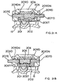
- FIGS. 19-20 illustrate another embodiment of the invention, where like numerals refer to like parts.
- the embodiment of FIGS. 19-20 is very similar to the embodiment of FIGS. 4-8, and only vary slightly. Nevertheless, the teachings of the embodiments discussed above are fully incorporated herein.
- buttons 207 are slidably attached to the adjuster 205 via a pin 207P.
- Buttons 207 have channels that slidably receive pin 207P, so that pin 207P can slide therein. Buttons 207 can move axially with adjuster 205 between the engaged and disengaged positions. However, buttons 207 are captured by cover 206, so that buttons 207 remain stationary relative thereto while adjuster 205 move vertically along upper and lower contact trips 201, 202.
- FIG. 20A shows adjuster 205 meshing with lower contact trip 202. If the user desires to change the overall length of the contact trip assembly 200, the user would push disengaging button 207D towards the position of FIG. 20B. The button 207D moves adjuster 205 until its teeth 205T do not engage with the teeth 202T of lower contact trip 202. The user can then move the lower contact trip 202 to the desired position.
- detent 209D can be placed on at least one button 207. Detent 209D would then engage a detent notch 209DN placed on cover 206.
- FIG. 21 illustrates yet another embodiment of the invention, where like numerals refer to like parts.
- the embodiment of FIG. 21 is very similar to the embodiment of FIGS. 19-20, and only vary slightly. Nevertheless, the teachings of the embodiments discussed above are fully incorporated herein.
- buttons 207 are not slidably attached to the adjuster 205 via a pin 207P. Instead, buttons 207 just contact surfaces of adjuster 205, so that buttons 207 can move adjuster 205 between the meshing and disengaged positions. However, buttons 207 are captured by cover 206, so that buttons 207 remain stationary relative thereto while adjuster 205 move vertically along upper and lower contact trips 201, 202.
- FIG. 20A shows adjuster 205 meshing with lower contact trip 202. If the user desires to change the overall length of the contact trip assembly 200, the user would push disengaging button 207D towards the position of FIG. 20B. The button 207D moves adjuster 205 until its teeth 205T do not engage with the teeth 202T of lower contact trip 202. The user can then move the lower contact trip 202 to the desired position.
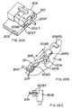
- FIG. 18 illustrates another embodiment of the invention, where like numerals refer to like parts.
- the embodiment of FIG. 18 is very similar to the embodiment of FIG. 21, and only vary slightly. Nevertheless, the teachings of the embodiments discussed above are fully incorporated herein.
- engaging button 207E is fixedly attached (or integral with) adjuster 205.
- disengaging button 207D contacts a surface of adjuster 205.
- disengaging buttons 207D is captured by cover 206, so that it remains stationary relative thereto while adjuster 205 move vertically along upper and lower contact trips 201, 202.
- a spring 207DS may be disposed between adjuster 205 and disengaging button 207D to bias button 207D outwardly of cover 206.
- FIG. 18A shows adjuster 205 meshing with lower contact trip 202. If the user desires to change the overall length of the contact trip assembly 200, the user would push disengaging button 207D. The button 207D moves adjuster 205 until its teeth 205T do not engage with the teeth 202T of lower contact trip 202. The user can then move the lower contact trip 202 to the desired position.
- a leaf spring 205DS may be wrapped around adjuster 205.
- One end of spring 205DS may be folded to create a detent that engages notches 201N formed on the upper contact trip 201.
- Spring 205DS may also have a detent bump 205DB. This bump 205DB would not necessarily maintain the adjuster 205 in the meshing or disengaged positions. Bump 205DB however would contact teeth 202T when the adjuster 205 is being moved between positions, providing an audible and/or tactile signal to the user.
- adjuster 205 may have a rail that slidably receives a button, so that the user can move adjuster 205 by pulling and pushing the button.
- FIG. 22 illustrates one such possible embodiment, where like numerals refer to like parts. Nevertheless, the teachings of the embodiments discussed above are fully incorporated herein.
- Adjuster 205 may have a rail 205R, which is slidably engaged a connector 210.
- Rail 205R may be shaped as a dovetail.
- connector 210 can remain stationary along a vertical axis when adjuster 205 moves along the vertical axis, but moves with adjuster 205 when adjuster 205 moves along a horizontal axis.
- the dovetail connection requires adjuster 205 and connector 210 to move together along the horizontal axis between the engaged and disengaged positions.
- Connector 210 has a post 210P, which is in turn connected to a button 210B.
- An activator 211 is used to move the button 210B (and adjuster 205) between the engaged and disengaged positions.
- Activator 211 is slidably attached to the cover 206 so that it can be moved along a vertical axis.
- activator 211 may have flanges 211F for capturing a cover rail 206R therein, allowing activator 211 to slide along the rail 206R.
- the range of movement may be limited at one end by a rail stop 206RS, which may be engaged by a rail stop 211RS.
- activator 211 may be detented in two positions by detents 206D on cover 206.
- Activator 211 may have a handle 211H for moving the activator 211.
- Activator 211 may also have an inclined rail 211R that is captured between two flanges 210BF of button 210B. Accordingly, the linear motion of activator 211 as it slides along cover 206 is translated into a substantially perpendicular motion as button 210B follows rail 211R. Persons skilled in the art will recognize that adjuster 205 will move between the engaged and disengaged positions as button 210B follows rail 211R.
- button 210B will move adjuster 205 until its teeth 205T do not engage with the teeth 202T of lower contact trip 202. The user can then move the lower contact trip 202 to the desired position. To fix the desired length of contact trip assembly 200, the user then needs to move activator 211 to its original position. Persons skilled in the art will recognize that this movement is necessary as no spring 204 is provided to move adjuster 205 outwardly back to the engaged position.
- FIG. 26 illustrates yet another embodiment of the invention, where like numerals refer to like parts. Nevertheless, the teachings of the embodiments discussed above are fully incorporated herein.
- knob 216 is used to move adjuster 205 between the engaged, or meshing, and disengaged positions.
- knob 216 has a body 216K, which is engaged to a housing 216H.
- housing 216H is made of plastic.
- Body 216K and housing 216H may be engaged via a bolt 216B.
- Body 216K and/or housing 216H preferably have a helical slot 216S.
- Slot 216S is preferably engaged by one end of follower 215.
- Follower 215 may be captured by housing 216H. Upon rotation of knob 216, follower 215 follows slot 216S, thus moving along its longitudinal axis, rather than rotating about knob 216. In other words, the rotational motion of knob 216 is converted into linear motion of follower 215.
- follower 215 preferably has a hook 215H, which may be disposed within slot 205S of adjuster 205.
- hook 215H is not captured by slot 205S.
- knob 216 will move follower 215 until it contacts adjuster 205, then follower 215 and adjuster 205 will move jointly until its teeth 205T do not engage with the teeth 202T of lower contact trip 202. The user can then move the lower contact trip 202 to the desired position.
- a user will not be able to move adjuster 205 and upper contact trip 201 along vertical axis V because of follower 215.
- knob 216 To fix the desired length of contact trip assembly 200, the user then needs to rotate knob 216 to its original position.
- spring 204 While spring 204 is not requires to move adjuster 205 outwardly back to the engaged position, it can still provide a force to maintain engagement between teeth 202T, 205T.
- knob 216 it may be desirable to provide a detent for knob 216, which would maintain the knob 216 in the engaged and/or disengaged positions.
- FIGS. 9-11 illustrate a further embodiment of the invention, where like numerals refer to like parts.
- Tool 10 is provided with an adjustable contact trip assembly 300.
- the contact trip assembly 300 preferably has an upper contact trip 301 for engaging trigger assembly 14 and a lower contact trip 302 for contacting a workpiece W.
- the contact trip assembly 300 is preferably slidably attached to the housing 15 and/or nosepiece 13 so that it slides vertically when the lower contact trip 302 contacts a workpiece W and the user pushes the fastening tool 10 unto the workpiece W.
- a spring 311 may be disposed between housing 15 and/or nosepiece 13 and contact trip assembly 300 to bias contact trip assembly 300 downwardly towards the workpiece W.
- Upper contact trip 301 and lower contact trip 302 preferably have teeth 301T and 302T, respectively, which mesh together.
- a cam mechanism 320 may be used to force teeth 301T and 302T to mesh and/or lock upper contact trip 301 and lower contact trip 302 in place.
- Cam mechanism 320 may include a shaft 321 extending through upper contact trip 301 and lower contact trip 302.
- the shaft 321 may have a head 321H disposed on the side of lower contact trip 302 farthest from upper contact trip 301.
- a cam 322 may be pivotally connected to shaft 321 and have a cam portion 322C that contacts upper contact trip 301.
- cam portion 322C changes the distance between cam pivot 322A and upper contact trip 301when cam 322 is pivoted about an axis substantially perpendicular to the longitudinal axis of shaft 321. If the user desires to change the overall length of the contact trip assembly 300, the user would rotate the cam 322, thus unmeshing teeth 301T, 302T, and move the lower contact trip 302 to the desired position. The user would then rotate cam 322 back to the locking position.
- upper contact trip 301 may be useful to provide upper contact trip 301 with a slot 301S to allow shaft 321 (and thus lower contact trip) to move vertically therein relative to upper contact trip 301.
- cam mechanism 322 may be disposed so that shaft 321 is captured by upper contact trip 301, rather than lower contact trip 302, and/or that cam 322 contact lower contact trip 302, rather than upper contact trip 301.
- FIGS. 12-13 illustrate an alternative cam mechanism 340, where like numerals refer to like parts.
- the teachings of the embodiments discussed above are fully incorporated herein.
- a cam mechanism 340 may be used to force teeth 301T and 302T to mesh and/or lock upper contact trip 301 and lower contact trip 302 in place.
- Cam mechanism 340 may include a shaft 341 extending through upper contact trip 301 and lower contact trip 302.
- the shaft 341 may have a head 341H disposed on the side of lower contact trip 302 farthest from upper contact trip 301.
- a cam 342 may be fixedly connected to shaft 341 so that shaft 341 and cam 342 rotate jointly about the longitudinal axis of shaft 341.
- Cam 342 may have a cam portion 342C that contacts cam portion 301C of upper contact trip 301.
- cam portion 342C changes the distance between cam portion 342C and lower contact trip 302 when cam 342 is pivoted. If the user desires to change the overall length of the contact trip assembly 300, the user would rotate the cam 342, thus unmeshing teeth 301T, 302T, and move the lower contact trip 302 to the desired position. The user would then rotate cam 342 back to the locking position.
- contact trip 302 may be useful to provide contact trip 302 with a slot 302S to allow shaft 341 (and thus lower contact trip 302) to move vertically therein relative to upper contact trip 301.
Landscapes
- Engineering & Computer Science (AREA)
- Mechanical Engineering (AREA)
- Portable Nailing Machines And Staplers (AREA)
- Push-Button Switches (AREA)
Abstract
Description
Claims (9)
- A fastening tool comprising:a housing;a magazine connected to the housing for storing a fastener;a driving mechanism disposed within the housing for driving the fastener into a workpiece;a trigger assembly pivotally attached to the housing for activating the driving mechanism, the trigger assembly comprising a main trigger pivotally attached to the housing, and a supplemental trigger pivotally attached to the main trigger;a contact trip assembly comprising an upper contact trip contacting the supplemental trigger, and a lower contact trip connected to the upper contact trip;an adjuster supported by one of the upper contact trip and the lower contact trip, the adjuster having teeth that can mesh with teeth disposed on the other of the upper contact trip and the lower contact trip, the adjuster being movable between a first position where the teeth of the adjuster and the other of the upper contact trip and the lower contact trip mesh, and a second position where the teeth of the adjuster and the other of the upper contact trip and the lower contact trip do not mesh; anda detent mechanism associated with the adjuster for maintaining the adjuster in at least one of the first and second positions.
- The fastening tool of Claim 1, wherein the detent mechanism comprises a detent element disposed on the adjuster and engaging a notch disposed on the lower contact trip.
- The fastening tool of Claim 2, further comprising a spring for biasing the detent element towards the notch.
- The fastening tool of Claim 1, wherein the adjuster further comprises a knob for moving the adjuster between the first and second positions.
- The fastening tool of Claim 4, wherein the detent mechanism comprises a protrusion disposed on the knob engaging a detent notch in the upper contact trip.
- The fastening tool of Claim 4, wherein the knob is only movable into and out of the housing.
- The fastening tool of Claim 1, wherein the detent mechanism comprises a spring engaging contacting the adjuster.
- A fastening tool comprising:a housing;a magazine connected to the housing for storing a fastener;a driving mechanism disposed within the housing for driving the fastener into a workpiece;a trigger assembly pivotally attached to the housing for activating the driving mechanism, the trigger assembly comprising a main trigger pivotally attached to the housing, and a supplemental trigger pivotally attached to the main trigger;a contact trip assembly comprising an upper contact trip contacting the supplemental trigger, and a lower contact trip connected to the upper contact trip;an adjuster supported by one of the upper contact trip and the lower contact trip, the adjuster having teeth that can mesh with teeth disposed on the other of the upper contact trip and the lower contact trip, the adjuster being movable between a first position where the teeth of the adjuster and the other of the upper contact trip and the lower contact trip mesh, and a second position where the teeth of the adjuster and the other of the upper contact trip and the lower contact trip do not mesh;a knob rotatably attached to the housing;a link connected to the adjuster at one end and to the knob at the other end for moving the adjuster between the first and second positions upon rotation of the knob.
- The fastening tool of Claim 8, wherein the knob has a channel for slidably receiving the link.
Priority Applications (1)
| Application Number | Priority Date | Filing Date | Title |
|---|---|---|---|
| EP06114180A EP1707319A3 (en) | 2001-01-31 | 2002-01-30 | Contact trip assembly for fastening tool |
Applications Claiming Priority (6)
| Application Number | Priority Date | Filing Date | Title |
|---|---|---|---|
| US26539901P | 2001-01-31 | 2001-01-31 | |
| US265399P | 2001-01-31 | ||
| US33889601P | 2001-11-06 | 2001-11-06 | |
| US338896P | 2001-11-06 | ||
| US10/054,137 US6705501B2 (en) | 2001-01-31 | 2002-01-22 | Contact trip assembly for fastening tool |
| US54137 | 2002-01-22 |
Related Child Applications (1)
| Application Number | Title | Priority Date | Filing Date |
|---|---|---|---|
| EP06114180A Division EP1707319A3 (en) | 2001-01-31 | 2002-01-30 | Contact trip assembly for fastening tool |
Publications (3)
| Publication Number | Publication Date |
|---|---|
| EP1234639A2 true EP1234639A2 (en) | 2002-08-28 |
| EP1234639A3 EP1234639A3 (en) | 2004-12-01 |
| EP1234639B1 EP1234639B1 (en) | 2006-10-25 |
Family
ID=27368579
Family Applications (1)
| Application Number | Title | Priority Date | Filing Date |
|---|---|---|---|
| EP02250631A Expired - Lifetime EP1234639B1 (en) | 2001-01-31 | 2002-01-30 | Contact trip adjustment for fastening tool |
Country Status (3)
| Country | Link |
|---|---|
| US (2) | US6705501B2 (en) |
| EP (1) | EP1234639B1 (en) |
| DE (1) | DE60215564T2 (en) |
Cited By (1)
| Publication number | Priority date | Publication date | Assignee | Title |
|---|---|---|---|---|
| EP1652625A3 (en) * | 2004-10-29 | 2010-11-10 | Black & Decker Inc. | Operational lock and depth adjustment for fastening tool |
Families Citing this family (39)
| Publication number | Priority date | Publication date | Assignee | Title |
|---|---|---|---|---|
| US20020117531A1 (en) | 2001-02-07 | 2002-08-29 | Schell Craig A. | Fastener tool |
| US6783044B2 (en) * | 2003-02-05 | 2004-08-31 | Stanley Fastening Systems, L.P. | Depth of drive adjustment for a fastener driving tool with removable contact member and method of exchanging contact members |
| US20060108391A1 (en) * | 2003-12-31 | 2006-05-25 | Leasure Jeremy D | Pneumatic fastener |
| US6959850B2 (en) * | 2004-02-27 | 2005-11-01 | Illinois Tool Works Inc. | Tool-less depth adjustment for fastener-driving tool |
| US7213732B2 (en) * | 2004-04-02 | 2007-05-08 | Black & Decker Inc. | Contact trip mechanism for nailer |
| US7165305B2 (en) * | 2004-04-02 | 2007-01-23 | Black & Decker Inc. | Activation arm assembly method |
| US7032797B2 (en) * | 2004-08-31 | 2006-04-25 | Falcon Pneumatic Inc. | Punching-depth adjusting device for use with a nailing gun |
| US7055729B2 (en) * | 2004-09-24 | 2006-06-06 | Illinois Tool Works Inc. | Tool-free depth-of-drive adjustment for a fastener-driving tool |
| US20060091168A1 (en) * | 2004-10-29 | 2006-05-04 | Ng Koon Y | Belt clip for hand-held power tool |
| JP5055817B2 (en) * | 2005-06-08 | 2012-10-24 | マックス株式会社 | Contact mechanism in driving tools |
| US7303103B2 (en) * | 2005-12-02 | 2007-12-04 | Nailermate Enterprise Corp. | Structure of arresting mechanism for nail guns |
| US20070251966A1 (en) * | 2006-04-28 | 2007-11-01 | De Poan Pneumatic Corp. | Impact protection for nail driver |
| US7942299B2 (en) * | 2006-05-31 | 2011-05-17 | Black & Decker Inc. | Hand tool with belt or rafter hook |
| US20080072717A1 (en) * | 2006-09-25 | 2008-03-27 | Stumpf William R | Drywall screwdriver bit |
| US8684245B2 (en) * | 2006-10-20 | 2014-04-01 | Stanley Fastening Systems, L.P. | Fastener driving device with mechanisms to limit movement of nails |
| US7427008B2 (en) * | 2006-10-25 | 2008-09-23 | Black & Decker Inc. | Depth adjusting device for a power tool |
| US7753243B2 (en) * | 2006-10-25 | 2010-07-13 | Black & Decker Inc. | Lock-out mechanism for a power tool |
| US7556184B2 (en) * | 2007-06-11 | 2009-07-07 | Black & Decker Inc. | Profile lifter for a nailer |
| JP5073380B2 (en) * | 2007-06-28 | 2012-11-14 | 株式会社マキタ | Electric driving tool |
| JP5133000B2 (en) * | 2007-06-28 | 2013-01-30 | 株式会社マキタ | Electric driving tool |
| US8931676B2 (en) | 2007-08-27 | 2015-01-13 | Black & Decker Inc. | Nailer having mechanism for pre-positioning nail |
| US8235270B2 (en) * | 2007-10-15 | 2012-08-07 | Illinois Tool Works Inc. | Fastening tool holding bracket |
| US8056785B2 (en) * | 2007-10-15 | 2011-11-15 | Illinois Tool Works Inc. | Moveable fastening tool holding bracket |
| US7641088B2 (en) * | 2008-03-21 | 2010-01-05 | Nailermate Enterprise Corporation | Nail gun with nail alignment adjustment device |
| US7934566B2 (en) * | 2008-08-14 | 2011-05-03 | Robert Bosch Gmbh | Cordless nailer drive mechanism sensor |
| US7934565B2 (en) | 2008-08-14 | 2011-05-03 | Robert Bosch Gmbh | Cordless nailer with safety sensor |
| US7905377B2 (en) | 2008-08-14 | 2011-03-15 | Robert Bosch Gmbh | Flywheel driven nailer with safety mechanism |
| US8136606B2 (en) | 2008-08-14 | 2012-03-20 | Robert Bosch Gmbh | Cordless nail gun |
| US8813220B2 (en) | 2008-08-20 | 2014-08-19 | The Boeing Company | Methods and systems for internet protocol (IP) packet header collection and storage |
| US9004119B2 (en) * | 2009-05-08 | 2015-04-14 | Diane Piper | Protective cover for use with handbags and a method for its use |
| US8292143B2 (en) | 2010-10-12 | 2012-10-23 | Stanley Fastening Systems, L.P. | Dry fire lockout with bypass for fastener driving device |
| US8348116B2 (en) * | 2010-12-06 | 2013-01-08 | Xu Jun-Xiu | Nail gun adaptable to nails of different length |
| US8408438B2 (en) * | 2011-02-18 | 2013-04-02 | Illinois Tool Works Inc. | Easy grip tool-free depth-of-drive adjustment |
| US8523038B2 (en) * | 2011-05-31 | 2013-09-03 | Testo Industry Corp. | Adjusting-fixing assembly for a staple gun |
| US11123850B2 (en) * | 2016-06-30 | 2021-09-21 | Black & Decker Inc. | Cordless concrete nailer with removable lower contact trip |
| US11141845B2 (en) | 2017-02-02 | 2021-10-12 | Illinois Tool Works Inc. | Combustion-powered tool with sleeve-retaining lockout device |
| TWI764899B (en) * | 2017-05-15 | 2022-05-21 | 鑽全實業股份有限公司 | Adjustable nailing depth nail gun |
| US11794323B2 (en) | 2021-03-11 | 2023-10-24 | Illinois Tool Works Inc. | Fastener-driving tool with chamber member retaining assembly |
| US12358112B2 (en) | 2021-03-11 | 2025-07-15 | Illinois Tool Works Inc. | Fastener-driving tool with chamber member retaining assembly |
Family Cites Families (10)
| Publication number | Priority date | Publication date | Assignee | Title |
|---|---|---|---|---|
| US3673922A (en) * | 1966-12-19 | 1972-07-04 | Fastener Corp | Fastener driving tool |
| US4928868A (en) * | 1983-03-17 | 1990-05-29 | Duo-Fast Corporation | Fastener driving tool |
| US5181450A (en) * | 1991-05-16 | 1993-01-26 | Umberto Monacelli | Pneumatic fastener driving apparatus with piston holding detent |
| JP2556818Y2 (en) * | 1991-09-21 | 1997-12-08 | 株式会社マキタ | Driving depth adjustment device for nailing machine |
| US5263842A (en) * | 1992-03-30 | 1993-11-23 | Stanley-Bostitch, Inc. | Nail driver with improved nosepiece assembly |
| US5452835A (en) * | 1994-08-01 | 1995-09-26 | Illinois Tool Works Inc. | Positioning mechanism for powered fastener-driving tool |
| JP3137227B2 (en) * | 1995-06-09 | 2001-02-19 | マックス株式会社 | Nail driver safety mechanism |
| US5687897A (en) * | 1995-07-28 | 1997-11-18 | Campbell Hausfeld/Scott Fetzer Company | Dual mode pneumatic tool |
| JP2002540967A (en) * | 1999-04-05 | 2002-12-03 | スタンレー ファスニング システムズ エル.ピー. | Fastener driving tool safety trip assembly and trip locking mechanism |
| US6116488A (en) * | 2000-02-23 | 2000-09-12 | Lee; Yun-Chung | Trigger switching structure of contact/full sequential actuation fastening tool |
-
2002
- 2002-01-22 US US10/054,137 patent/US6705501B2/en not_active Expired - Lifetime
- 2002-01-30 DE DE60215564T patent/DE60215564T2/en not_active Expired - Fee Related
- 2002-01-30 EP EP02250631A patent/EP1234639B1/en not_active Expired - Lifetime
-
2004
- 2004-01-29 US US10/768,727 patent/US6997365B2/en not_active Expired - Fee Related
Cited By (1)
| Publication number | Priority date | Publication date | Assignee | Title |
|---|---|---|---|---|
| EP1652625A3 (en) * | 2004-10-29 | 2010-11-10 | Black & Decker Inc. | Operational lock and depth adjustment for fastening tool |
Also Published As
| Publication number | Publication date |
|---|---|
| DE60215564T2 (en) | 2007-08-30 |
| EP1234639B1 (en) | 2006-10-25 |
| US6997365B2 (en) | 2006-02-14 |
| US20020108997A1 (en) | 2002-08-15 |
| US20040245312A1 (en) | 2004-12-09 |
| EP1234639A3 (en) | 2004-12-01 |
| US6705501B2 (en) | 2004-03-16 |
| DE60215564D1 (en) | 2006-12-07 |
Similar Documents
| Publication | Publication Date | Title |
|---|---|---|
| EP1234639B1 (en) | Contact trip adjustment for fastening tool | |
| EP0640445B1 (en) | Spring actuated fastener driving tool | |
| EP1729939B1 (en) | Contact trip mechanism for nailer | |
| US4452388A (en) | Spring actuated staple driving device | |
| US20070034664A1 (en) | Spring-powered stapler | |
| JP4499556B2 (en) | Hand-held stroke saw machine with saw blade guidance system | |
| EP1106095B1 (en) | Seat belt buckle for use with a pretensioner | |
| JP4020974B2 (en) | Tightening mechanism for power tools | |
| CA1205952A (en) | Stapling tool | |
| US7571840B2 (en) | Safety of nailing device | |
| EP1707319A2 (en) | Contact trip assembly for fastening tool | |
| EP0959707B1 (en) | Buckle | |
| JP2002518069A (en) | Seat belt buckles used with pretensioners | |
| US11149900B2 (en) | Tripod leg spreader | |
| US3095574A (en) | Handle lock for stapling devices | |
| US4729527A (en) | Slide switch of anti-reverse mechanism for fishing reel | |
| CA2164393C (en) | Electric hair trimmer | |
| EP1095740B1 (en) | Staple gun wire guide | |
| JPH079361A (en) | Single and continuous driving switchover mechanism in nail feeding device | |
| KR930012155B1 (en) | Floppy Disk Drive Disk Loading Device | |
| JPH0631652A (en) | Feed mechanism for staple in electrically-driven stapler | |
| JPH07229335A (en) | Surface fitting type electric lock | |
| AU2007202194A1 (en) | Improved Fastening Device |
Legal Events
| Date | Code | Title | Description |
|---|---|---|---|
| PUAI | Public reference made under article 153(3) epc to a published international application that has entered the european phase |
Free format text: ORIGINAL CODE: 0009012 |
|
| 17P | Request for examination filed |
Effective date: 20020130 |
|
| AK | Designated contracting states |
Kind code of ref document: A2 Designated state(s): AT BE CH CY DE DK ES FI FR GB GR IE IT LI LU MC NL PT SE TR |
|
| AX | Request for extension of the european patent |
Free format text: AL;LT;LV;MK;RO;SI |
|
| PUAL | Search report despatched |
Free format text: ORIGINAL CODE: 0009013 |
|
| AK | Designated contracting states |
Kind code of ref document: A3 Designated state(s): AT BE CH CY DE DK ES FI FR GB GR IE IT LI LU MC NL PT SE TR |
|
| AX | Request for extension of the european patent |
Extension state: AL LT LV MK RO SI |
|
| AKX | Designation fees paid |
Designated state(s): DE FR GB IT |
|
| GRAP | Despatch of communication of intention to grant a patent |
Free format text: ORIGINAL CODE: EPIDOSNIGR1 |
|
| GRAS | Grant fee paid |
Free format text: ORIGINAL CODE: EPIDOSNIGR3 |
|
| GRAA | (expected) grant |
Free format text: ORIGINAL CODE: 0009210 |
|
| AK | Designated contracting states |
Kind code of ref document: B1 Designated state(s): DE FR GB IT |
|
| REG | Reference to a national code |
Ref country code: GB Ref legal event code: FG4D |
|
| REF | Corresponds to: |
Ref document number: 60215564 Country of ref document: DE Date of ref document: 20061207 Kind code of ref document: P |
|
| ET | Fr: translation filed | ||
| PG25 | Lapsed in a contracting state [announced via postgrant information from national office to epo] |
Ref country code: DE Free format text: LAPSE BECAUSE OF NON-PAYMENT OF DUE FEES Effective date: 20070801 |
|
| PLBE | No opposition filed within time limit |
Free format text: ORIGINAL CODE: 0009261 |
|
| STAA | Information on the status of an ep patent application or granted ep patent |
Free format text: STATUS: NO OPPOSITION FILED WITHIN TIME LIMIT |
|
| GBPC | Gb: european patent ceased through non-payment of renewal fee |
Effective date: 20070130 |
|
| 26N | No opposition filed |
Effective date: 20070726 |
|
| PG25 | Lapsed in a contracting state [announced via postgrant information from national office to epo] |
Ref country code: GB Free format text: LAPSE BECAUSE OF NON-PAYMENT OF DUE FEES Effective date: 20070130 |
|
| PG25 | Lapsed in a contracting state [announced via postgrant information from national office to epo] |
Ref country code: FR Free format text: LAPSE BECAUSE OF NON-PAYMENT OF DUE FEES Effective date: 20070131 |
|
| PG25 | Lapsed in a contracting state [announced via postgrant information from national office to epo] |
Ref country code: IT Free format text: LAPSE BECAUSE OF NON-PAYMENT OF DUE FEES Effective date: 20070130 |
|
| REG | Reference to a national code |
Ref country code: FR Ref legal event code: ST Effective date: 20111125 |