EP1234545A2 - Instrument for inserting graft fixation device - Google Patents
Instrument for inserting graft fixation device Download PDFInfo
- Publication number
- EP1234545A2 EP1234545A2 EP02251291A EP02251291A EP1234545A2 EP 1234545 A2 EP1234545 A2 EP 1234545A2 EP 02251291 A EP02251291 A EP 02251291A EP 02251291 A EP02251291 A EP 02251291A EP 1234545 A2 EP1234545 A2 EP 1234545A2
- Authority
- EP
- European Patent Office
- Prior art keywords
- distal end
- instrument
- seen
- members
- longitudinal axis
- Prior art date
- Legal status (The legal status is an assumption and is not a legal conclusion. Google has not performed a legal analysis and makes no representation as to the accuracy of the status listed.)
- Granted
Links
Images












Classifications
-
- A—HUMAN NECESSITIES
- A61—MEDICAL OR VETERINARY SCIENCE; HYGIENE
- A61B—DIAGNOSIS; SURGERY; IDENTIFICATION
- A61B17/00—Surgical instruments, devices or methods
- A61B17/068—Surgical staplers, e.g. containing multiple staples or clamps
-
- A—HUMAN NECESSITIES
- A61—MEDICAL OR VETERINARY SCIENCE; HYGIENE
- A61B—DIAGNOSIS; SURGERY; IDENTIFICATION
- A61B17/00—Surgical instruments, devices or methods
- A61B17/04—Surgical instruments, devices or methods for suturing wounds; Holders or packages for needles or suture materials
- A61B17/0401—Suture anchors, buttons or pledgets, i.e. means for attaching sutures to bone, cartilage or soft tissue; Instruments for applying or removing suture anchors
-
- A—HUMAN NECESSITIES
- A61—MEDICAL OR VETERINARY SCIENCE; HYGIENE
- A61B—DIAGNOSIS; SURGERY; IDENTIFICATION
- A61B17/00—Surgical instruments, devices or methods
- A61B17/064—Surgical staples, i.e. penetrating the tissue
- A61B17/0642—Surgical staples, i.e. penetrating the tissue for bones, e.g. for osteosynthesis or connecting tendon to bone
-
- A—HUMAN NECESSITIES
- A61—MEDICAL OR VETERINARY SCIENCE; HYGIENE
- A61B—DIAGNOSIS; SURGERY; IDENTIFICATION
- A61B17/00—Surgical instruments, devices or methods
- A61B17/56—Surgical instruments or methods for treatment of bones or joints; Devices specially adapted therefor
- A61B17/58—Surgical instruments or methods for treatment of bones or joints; Devices specially adapted therefor for osteosynthesis, e.g. bone plates, screws or setting implements
- A61B17/88—Osteosynthesis instruments; Methods or means for implanting or extracting internal or external fixation devices
- A61B17/92—Impactors or extractors, e.g. for removing intramedullary devices
-
- A—HUMAN NECESSITIES
- A61—MEDICAL OR VETERINARY SCIENCE; HYGIENE
- A61B—DIAGNOSIS; SURGERY; IDENTIFICATION
- A61B17/00—Surgical instruments, devices or methods
- A61B2017/00004—(bio)absorbable, (bio)resorbable or resorptive
-
- A—HUMAN NECESSITIES
- A61—MEDICAL OR VETERINARY SCIENCE; HYGIENE
- A61B—DIAGNOSIS; SURGERY; IDENTIFICATION
- A61B17/00—Surgical instruments, devices or methods
- A61B17/04—Surgical instruments, devices or methods for suturing wounds; Holders or packages for needles or suture materials
- A61B17/0401—Suture anchors, buttons or pledgets, i.e. means for attaching sutures to bone, cartilage or soft tissue; Instruments for applying or removing suture anchors
- A61B2017/0409—Instruments for applying suture anchors
-
- A—HUMAN NECESSITIES
- A61—MEDICAL OR VETERINARY SCIENCE; HYGIENE
- A61B—DIAGNOSIS; SURGERY; IDENTIFICATION
- A61B17/00—Surgical instruments, devices or methods
- A61B17/04—Surgical instruments, devices or methods for suturing wounds; Holders or packages for needles or suture materials
- A61B17/0401—Suture anchors, buttons or pledgets, i.e. means for attaching sutures to bone, cartilage or soft tissue; Instruments for applying or removing suture anchors
- A61B2017/0412—Suture anchors, buttons or pledgets, i.e. means for attaching sutures to bone, cartilage or soft tissue; Instruments for applying or removing suture anchors having anchoring barbs or pins extending outwardly from suture anchor body
-
- A—HUMAN NECESSITIES
- A61—MEDICAL OR VETERINARY SCIENCE; HYGIENE
- A61B—DIAGNOSIS; SURGERY; IDENTIFICATION
- A61B17/00—Surgical instruments, devices or methods
- A61B17/04—Surgical instruments, devices or methods for suturing wounds; Holders or packages for needles or suture materials
- A61B17/0401—Suture anchors, buttons or pledgets, i.e. means for attaching sutures to bone, cartilage or soft tissue; Instruments for applying or removing suture anchors
- A61B2017/0419—H-fasteners
-
- A—HUMAN NECESSITIES
- A61—MEDICAL OR VETERINARY SCIENCE; HYGIENE
- A61B—DIAGNOSIS; SURGERY; IDENTIFICATION
- A61B17/00—Surgical instruments, devices or methods
- A61B17/04—Surgical instruments, devices or methods for suturing wounds; Holders or packages for needles or suture materials
- A61B17/0401—Suture anchors, buttons or pledgets, i.e. means for attaching sutures to bone, cartilage or soft tissue; Instruments for applying or removing suture anchors
- A61B2017/0427—Suture anchors, buttons or pledgets, i.e. means for attaching sutures to bone, cartilage or soft tissue; Instruments for applying or removing suture anchors having anchoring barbs or pins extending outwardly from the anchor body
-
- A—HUMAN NECESSITIES
- A61—MEDICAL OR VETERINARY SCIENCE; HYGIENE
- A61B—DIAGNOSIS; SURGERY; IDENTIFICATION
- A61B17/00—Surgical instruments, devices or methods
- A61B17/04—Surgical instruments, devices or methods for suturing wounds; Holders or packages for needles or suture materials
- A61B17/0401—Suture anchors, buttons or pledgets, i.e. means for attaching sutures to bone, cartilage or soft tissue; Instruments for applying or removing suture anchors
- A61B2017/0445—Suture anchors, buttons or pledgets, i.e. means for attaching sutures to bone, cartilage or soft tissue; Instruments for applying or removing suture anchors cannulated, e.g. with a longitudinal through-hole for passage of an instrument
-
- A—HUMAN NECESSITIES
- A61—MEDICAL OR VETERINARY SCIENCE; HYGIENE
- A61B—DIAGNOSIS; SURGERY; IDENTIFICATION
- A61B17/00—Surgical instruments, devices or methods
- A61B17/064—Surgical staples, i.e. penetrating the tissue
- A61B2017/0646—Surgical staples, i.e. penetrating the tissue for insertion into cartillege, e.g. meniscus
-
- A—HUMAN NECESSITIES
- A61—MEDICAL OR VETERINARY SCIENCE; HYGIENE
- A61B—DIAGNOSIS; SURGERY; IDENTIFICATION
- A61B17/00—Surgical instruments, devices or methods
- A61B17/064—Surgical staples, i.e. penetrating the tissue
- A61B2017/0647—Surgical staples, i.e. penetrating the tissue having one single leg, e.g. tacks
-
- A—HUMAN NECESSITIES
- A61—MEDICAL OR VETERINARY SCIENCE; HYGIENE
- A61F—FILTERS IMPLANTABLE INTO BLOOD VESSELS; PROSTHESES; DEVICES PROVIDING PATENCY TO, OR PREVENTING COLLAPSING OF, TUBULAR STRUCTURES OF THE BODY, e.g. STENTS; ORTHOPAEDIC, NURSING OR CONTRACEPTIVE DEVICES; FOMENTATION; TREATMENT OR PROTECTION OF EYES OR EARS; BANDAGES, DRESSINGS OR ABSORBENT PADS; FIRST-AID KITS
- A61F2/00—Filters implantable into blood vessels; Prostheses, i.e. artificial substitutes or replacements for parts of the body; Appliances for connecting them with the body; Devices providing patency to, or preventing collapsing of, tubular structures of the body, e.g. stents
- A61F2/0063—Implantable repair or support meshes, e.g. hernia meshes
-
- A—HUMAN NECESSITIES
- A61—MEDICAL OR VETERINARY SCIENCE; HYGIENE
- A61F—FILTERS IMPLANTABLE INTO BLOOD VESSELS; PROSTHESES; DEVICES PROVIDING PATENCY TO, OR PREVENTING COLLAPSING OF, TUBULAR STRUCTURES OF THE BODY, e.g. STENTS; ORTHOPAEDIC, NURSING OR CONTRACEPTIVE DEVICES; FOMENTATION; TREATMENT OR PROTECTION OF EYES OR EARS; BANDAGES, DRESSINGS OR ABSORBENT PADS; FIRST-AID KITS
- A61F2/00—Filters implantable into blood vessels; Prostheses, i.e. artificial substitutes or replacements for parts of the body; Appliances for connecting them with the body; Devices providing patency to, or preventing collapsing of, tubular structures of the body, e.g. stents
- A61F2/02—Prostheses implantable into the body
- A61F2/08—Muscles; Tendons; Ligaments
- A61F2/0811—Fixation devices for tendons or ligaments
-
- A—HUMAN NECESSITIES
- A61—MEDICAL OR VETERINARY SCIENCE; HYGIENE
- A61F—FILTERS IMPLANTABLE INTO BLOOD VESSELS; PROSTHESES; DEVICES PROVIDING PATENCY TO, OR PREVENTING COLLAPSING OF, TUBULAR STRUCTURES OF THE BODY, e.g. STENTS; ORTHOPAEDIC, NURSING OR CONTRACEPTIVE DEVICES; FOMENTATION; TREATMENT OR PROTECTION OF EYES OR EARS; BANDAGES, DRESSINGS OR ABSORBENT PADS; FIRST-AID KITS
- A61F2/00—Filters implantable into blood vessels; Prostheses, i.e. artificial substitutes or replacements for parts of the body; Appliances for connecting them with the body; Devices providing patency to, or preventing collapsing of, tubular structures of the body, e.g. stents
- A61F2/02—Prostheses implantable into the body
- A61F2/28—Bones
- A61F2/2846—Support means for bone substitute or for bone graft implants, e.g. membranes or plates for covering bone defects
Definitions
- the field of art to which this invention relates is surgical fastening devices, in particular, surgical fastening devices for fixating tissue grafts to bone.
- tissue engineering has advanced at a rapid pace.
- cells from the human body for example, chondrocytes and fibrochrondrocytes from the knee joint.
- These autologous cells are then cultured in a laboratory environment on a bioabsorbable matrix.
- the matrix will typically have a shape substantially similar to the tissue section which needs to be replaced.
- the harvested cells will grow on the matrix to form an implantable section of tissue having substantially the same physical configuration as the section of tissue which needs to be replaced in the patient.
- tissue-engineered construct consisting of cells on the matrix (or, alternatively, consisting of a matrix alone without cells) is then affixed to the bone site using conventionally known surgical fasteners including sutures, periosteal coverings, or fibrin glue.
- tissue engineering are many, not the least of which is, for example, that it is now possible to replace cartilage with living cartilage tissue.
- the likelihood of rejection of the tissue implant is minimized since the cartilage tissue which has been grown in-vitro is identical to the autologous cartilage of the patient.
- the graft fixation device has first and second implantation members.
- the members are elongated and preferably have a cylindrical configuration.
- the members also have distal ends, proximal ends, and longitudinal axes. There are longitudinal passages extending through the entire length of each implantation member.
- the members have outer surfaces.
- the implantation members are connected to each other by a rod member having first and second ends and a central section. The first end of the rod member extends from the proximal end of the first implantation member and the second end of the rod member extends from the proximal end of the second implantation member.
- the rod member is preferably relatively rigid and may be configured to have a variety of geometric shapes, for example, an inverted "U" shape.
- the rod member may also be flexible.
- the rod member maintains the implantation members at a relatively fixed distance from each other.
- the central section of the rod member is designed to engage a section of a tissue-engineered matrix implant.
- the implantation members have a series of ridges extending out from the outer surfaces of the implantation members to assist in preventing withdrawal from a bone site or other anchoring site after the implantation members are implanted into previously-created bore holes.
- Yet another aspect of the present invention is a method of using the graft fixation device of the present invention to affix a matrix containing tissue-engineered tissue to a bone.
- Still yet another aspect of the present invention is a graft fixation device combination which is the combination of a fixation device and an insertion member.
- the fixation device has a first implantation member.
- the implantation member has a longitudinal axis, a proximal end, a distal end, an outer surface, and a longitudinal passage therethrough.
- the fixation device also has a second implantation member.
- the second implantation member has a longitudinal axis, a proximal end, a distal end, an outer surface, and a longitudinal passage therethrough.
- Each implantation member has a proximal annular face on its proximal end surrounding the longitudinal passages.
- the connecting member has a central section, a first end extending from the first implantation member and a second end extending from the second implantation member.
- Each insertion device is a member having a proximal end, a distal tapered end and a longitudinal passage therethrough. The distal end of each implantation member is in engagement with the proximal end of an insertion device.
- the instrument has a removable distal end housing and removable prongs.
- the instrument has an elongated member having a proximal end, a distal end, a distal end surface, and an outer surface. Outer screw threads extend out from the outer surface about the distal end.
- Inner screw threads extend out from the inner surface of the hollow member.
- a pair of spaced apart prong holes extend through the distal end of the hollow member, said prong holes being in communication with the cavity.
- a retention groove extends into the inner surface of the distal end of the hollow member.
- prongs having elongated members having distal ends and proximal ends.
- a piercing point extending distally from the distal end of each prong.
- a retention member is mounted to the proximal end of each prong, and the retention member has a proximal surface. The instrument is assembled by inserting the prongs through the prong holes, such that the prongs extend through the prong holes, and the proximal retention members are contained within the retention groove.
- the hollow member is then screwed onto the distal end of the elongated member, by engaging the mating inner threads with the outer threads, and rotating the hollow member until the distal end surface of the elongated member is in engagement with the proximal surfaces of the retention members.
- Still yet another aspect of the present invention is the combination of the insertion instrument as described above and a graft fixation device and combination of the present invention.
- a further aspect of the present invention is an instrument for inserting a graft fixation device into bone.
- the instrument has a mounting member having a first end, an opposed second end, a top and a bottom.
- the distal end of the slide rod is mounted to the first end of the mounting member such that the longitudinal axis of the mounting rod is angulated at an acute angle with respect to the mounting member.
- a hammer handle member is slidably mounted to the slide rod.
- the hammer handle has a distal end, a proximal end, an outer surface, a first flange member extending from the proximal end, a second flange member extending from the distal end, an inner passage therethrough and a longitudinal axis.
- the angulated distal end has a longitudinal axis and the proximal end of the mounting rod is mounted to the second end of the mounting member.
- a pair of spaced apart prongs extends longitudinally from the distal end of the mounting rod.
- the longitudinal axis of the slide rod is parallel to the longitudinal axis of the angulated distal end of the mounting rod.
- Another aspect of the present invention is a method of using the above-described surgical instrument to perform a surgical procedure.
- the graft fixation devices of the present invention can be made from conventional bio-compatible materials, including absorbable and non-absorbable materials, as well as biodegradable materials.
- the non-absorbable materials which can be utilized include conventional biocompatible materials such as stainless steel, polyethylene, Teflon, Nitinol, non-absorbable polymers, other bio-compatible metals, ceramics, combinations thereof and the like.
- the absorbable materials which can be used to manufacture the graft fixation devices of the present invention will typically include those conventional bioabsorbable or bioresorbable materials known in this art which can be effectively molded or machined.
- the bio-absorbable and bio-resorbable materials include polylactic acid, polydioxanone, polycaprolactone, polyglycolic acid, polygalactic acid, other known biocompatible bioabsorbable and bioresorbable polymers, ceramics, composites, combinations thereof and the like and equivalents thereof.
- the graft fixation device 10 is seen to have implantation members 20.
- the implantation members 20 are seen to be elongated members, preferably having a substantially cylindrical shape.
- the members 20 may have other geometric shapes including conical, pyramidal, polygonal, cubic, spherical, etc.
- the implantation members 20 0are seen to have distal ends 22 and proximal ends 24.
- Each implantation member 20 is seen to have an outer surface 28 and a longitudinal axis 29.
- Each member 20 is also seen to have longitudinal passage 35 extending therethrough.
- the implantation members 20 are also seen to have optional frustoconical ends 30, and proximal endface surfaces 32.
- endface surfaces 32 be flat, endface surface 32 may also be angled, concave, convex, etc.
- Endface surface 32 is seen to have central circular opening 36 in communication with passage 35.
- central opening 36 will have a circular cross-section, but it may have other geometric cross-sections as well including elliptical, polygonal, square, rectangular, combinations thereof and the like.
- Members 20 are also seen to have distal end face surfaces 37 having circular openings 38 in communication with passages 35. As shown with the optional frustoconical end 30, the annular end face surface 37 is of de minimis thickness around opening 38, however this thickness would increase in the absence of a frustoconical end.
- Also seen to extend out from the surface 28 of member 20 are a series of optional projections 40 having tissue engagement edges 44. Without the projections 40, the surface 28 of the member 20 will be smooth.
- the device 10 is seen to have graft retention member 50 connecting the implantation members 20.
- Retention member 50 is seen to be a rod-like member having first end 52, second end 54 and central section 55.
- First end 52 is seen to extend from proximal endface surface 32 of the first member 20 while end 54 is seen to extend up from the proximal endface surface 32 of the other member 20.
- the ends 54 and 52 of retention member 50 may also if desired extend from or be mounted to any section of outer surface 28.
- the connecting member 50 is seen to be preferably bent or shaped into three segments including top segment 55 and leg segments 56.
- the top segment 55 is seen to be substantially perpendicular to the leg segments 56.
- connecting member 50 may have other geometric configurations including semicircular, arced, curved, triangular, polygonal, U-shaped, and the like and combinations thereof.
- the ends 52 and 54 of connecting member 50 may be permanently affixed to the implantation members 20, or may be removably attached thereto in a conventional manner.
- Member 50 may be rigid or flexible. Member 50 will have a sufficient surface area to effectively retain a tissue-engineered matrix in place on a bone or other body surface.
- connecting member 50 will have a circular cross-section, but may have other geometric cross-sections as well including elliptical, polygonal, square, rectangular, combinations thereof and the like.
- Member 50 may be rigid or flexible, and may have a single filamentary structure or have multiple interconnected filaments or members.
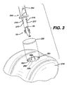
- FIGS. 3-8 the use of the graft fixation devices 10 of the present invention in a surgical procedure is illustrated.
- the initial step prior to the installation of a matrix containing a tissue-engineered tissue using a graft fixation device 10 of the present invention, is to drill or "tap" two bore holes 200 into a bone 210, for example, subchondral bone in the knee joint.
- the bore holes 200 are seen to be cylindrical holes having a bottom 208 and an open top 202 and side walls 205.
- the bore holes may be bone tunnels with a continuous passage and no bottom, or an open bottom. It is particularly preferred to tap the holes in the bone by using an instrument 400 as illustrated in FIG.
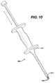
- tapping or “tap” as used herein is defined to mean a procedure wherein the distal pointed prongs 420 extending from the distal end 415 of the shaft 405 of instrument 400 are located over a bone site, and the proximal end 410 of instrument 400 is tapped or hit with slidable hammer handle 450 (of the "slap hammer"), which slides on shaft 460 between proximal end 410 and proximal stop 470, to form the bone bore holes 200.
- the distal end 465 of shaft 460 is connected to proximal end 411.
- Proximal stop 470 is mounted to proximal end 467.
- Hammer handle 450 is seen to have grasping section 451, collars 455 and longitudinal passage 457.
- a similar pointed instrument may be used to "tap" in the bore holes into bone, that is, any instrument having a nail-like distal end.
- one bone bore hole at a time may be "tapped” in. If the surgeon decides to drill the bore holes into bone, any conventional surgical drilling apparatus may be used.
- the matrix 220 containing tissue-engineering tissue is placed upon the bone surface 201 by the surgeon as seen in FIG. 4.
- the graft fixation device 10 is mounted on to the insertion instrument 250.
- Insertion instrument 250 is seen to be an elongated rod 260 having a proximal end 262 and a distal end 264. Mounted to the distal end 264 of the rod 260 is the depth stop 290.
- the depth stop 290 is seen to be a substantially rectangular member which is mounted perpendicular to the longitudinal axis 251 of the rod 260. Depth stop 290 is seen to have bottom 292. Extending distally from the bottom 292 of plate member 290 is a pair of parallel, spaced-apart, mounting prongs 270.
- the mounting prongs 270 are seen to be substantially rod-like members having distal pointed tips 277 and proximal ends 272.
- the prongs 270 are seen to have first section 273 and distal section 275.
- Section 273 is seen to have a greater cross-sectional dimension than distal section 275 such that the entire section 275 is insertable into passages 35 of members 20, while proximal section 273 is not insertable therein.
- Instrument 250 is also seen to have a "slap hammer section” consisting of proximal shaft 300 extending from proximal end 262, slidable hammer handle 320 (the "slap hammer”) which is slidable upon shaft 300 between proximal end 262, and proximal stop 330.
- Hammer handle member 320 is seen to have grasping section 325, end collars 327 and longitudinal passage 329.
- the graft fixation device 10 is mounted to the insertion instrument 250 by sliding the implantation members 20 onto the prongs 270 such that the distal sections 275 of members 270 are engaged within the longitudinal passages 35 of members 20 and distal points 277 protrude beyond the end of distal endface surfaces 37. Then, as seen in FIGS. 5 and 6, the instrument 250 is manipulated such that the graft fixation device 10 is inserted through matrix 220 and into bone 210 by moving the implantation members 20 mounted on prongs 270 into the bore holes 200 such that the members 20 are engaged in the bore holes 200, and such that the tissue engagement section 55 of the retention member 50 engages the matrix 220 such that the matrix 220 is firmly engaged against the surface 201 of the bone 210.
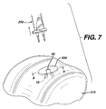
- holes may be cut into matrix 220 prior to insertion of device 10. Then, as seen in FIG. 7, the insertion instrument 250 is withdrawn proximally causing the prongs 270 to be withdrawn from the passages 35 of the implantation members 20, thereby leaving the graft fixation device 10 engaged in the bone bore holes, and causing the matrix 220 to be maintained in engagement with the surface 201 of bone 210.
- the "slap hammer" section of instrument 250 may assist in removal of the prongs.
- a cross-sectional view illustrating the device 10 engaged in bone 210 while maintaining the matrix 220 on bone surface 201 is seen in FIG. 8.
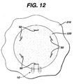
- FIG. 12 illustrates a matrix 220 mounted to bone surface 201 of bone 210 having multiple fixation devices of the present invention installed to secure the matrix 220.
- the number, anatomical location and orientation of fixation devices 10 necessary to provide sufficiently effective fixation will vary with the size and type of implant or matrix, the type of tissue, the age of the patient, the size of the patient's defect, the size of the fixation devices, the material of construction of the fixation devices, the load on the tissue at the repair site, etc.
- the size of the fixation devices of the present invention will vary in accordance with a number of variables including the specific design of the device, the materials of construction, the specific application for the devices, the type of surgical procedure, etc.
- the size of the matrices fixated with these devices will similarly vary.
- the Figures which are part of this specification are merely schematic and illustrative of the device and method of the present invention; the actual dimensions of the devices and matrices may vary in practice.
- a punch tool 400 was used to create the two requisite bore holes in the subchondral bone to receive one graft fixation device of the present invention. Only one polydioxanone device (4mm tip-to-tip distance) was used to attach each matrix. To create the bore holes, the punch tool was centered in the defect, oriented in the sagittal plane, and hit or "tapped" with a slap hammer repeatedly until it penetrated several millimeters into the subchondral bone. Next, a 7mm diameter circular collagen matrix, saturated with saline, was placed in the defect and then blotted dry to remove excess saline.
- the device and inserter tool were centered above the matrix and oriented in the sagittal plane.
- the surgeon then located the previously created bore holes by slowly advancing the distal tips of the inserter through the matrix.
- a hammer was used to fully advance the inserter tool (and implantation members 20 of the fixation device 10) through the matrix and into the subchondral bone.
- the inserter tool had a depth stop to prevent the implantation members 20 from being inserted too deeply, thereby assuring the proper placement of the implantation members through the matrix.
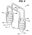
- FIG. 9 Another embodiment of the fixation device of the present invention having multiple retention members is seen in FIG. 9.
- the device 300 is seen to have a pair of implantation members 310.
- the implantation members 310 are substantially cylindrical members having longitudinal axis 311, distal ends 314 and proximal ends 312.
- Each implantation member 310 is seen to have a longitudinal passage 320.
- the members 310 are seen to have a distal frustoconical end 330, outer surface 350, and ridges 355 extending outward from surface 350.
- the members 310 are seen to be connected by a pair of retention members 340, having first and second ends 342 and 344 respectively.
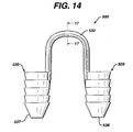
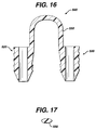
- FIGS. 13-17 Yet another embodiment of a fixation device of the present invention is illustrated in FIGS. 13-17.
- the graft fixation device 500 is seen to have implantation members 520.
- the implantation members 520 are seen to be elongated members, preferably having a substantially cylindrical shape.
- the members 520 may have other geometric shapes including conical, pyramidal, polygonal, cubic, spherical, etc.
- the implantation members 520 are seen to have distal ends 522 and proximal ends 524.
- Each implantation member 520 is seen to have an outer surface 528 and a longitudinal axis 529.
- Each member 520 is also seen to have longitudinal passage 535 extending therethrough.
- the implantation members 520 are also seen to have optional frustoconical ends 530, and proximal end face surfaces 532. Although it is preferred that endface surfaces 532 be flat, endface surfaces 532 may also be angled, concave, convex, etc.
- Each endface surface 532 is seen to have central circular opening 536 in communication with passage 535.
- central opening 536 will have a circular cross-section, but it may have other geometric cross-sections as well including elliptical, polygonal, square, rectangular, combinations thereof and the like.
- Members 520 are also seen to have distal end face surfaces 537 having circular openings 538 in communication with passages 535.
- endface surfaces 537 have a sharp edge configuration, but may also have various widths with a rounded or flat configuration.
- the annular end face surface 537 is of de minimis thickness around opening 538, however this thickness would typically increase in the absence of a frustoconical end.
- the end surface 537 could have various widths as previously mentioned.
- Also seen to extend out from the surface 528 of member 520 are a series of optional projections 540 having tissue engagement edges 544.
- the surface 528 of the member 520 will be smooth, however, it will be appreciated that surface 528 could be rough, or could have a variety of conventional projections such as cones, hemispheres, rods, hooks, etc., and the like and equivalents thereof.
- the device 500 is seen to have graft retention member 550 connecting the implantation members 520.
- Retention member 550 is seen to be a band-like member preferably having an oval cross-section.
- the retention member 550 is seen to have first end 552, second end 554 and central section 555.
- First end 552 is seen to extend up from proximal endface surface 532 of the first member 520 while end 554 is seen to extend up from the proximal endface surface 532 of the other member 520.
- a section 557 of end 552 is seen to extend out from section 539 of surface 528, while section 558 of second end 554 is also seen to extend out from a section 539 of surface 528.
- the ends 554 and 552 of retention member 550 may if desired extend from or be mounted to any section of outer surface 528.
- the connecting member 550 is seen to be preferably bent or shaped into three segments including top segment 555 and leg segments 556.
- the top segment 555 is seen to an arc shaped member, and the leg segments 56 are seen to be preferably perpendicular to surfaces 532.
- connecting member 550 may have other geometric configurations including semicircular, arced, curved, triangular, polygonal, V-shaped, and the like and combinations thereof.
- connecting member 550 may be permanently affixed to the implantation members 520, or may be removably attached thereto in a variety of conventional manners, for example, a ball and socket joint, a plug joint, etc.
- Member 550 may be rigid or flexible. Member 550 will have a sufficient surface area to effectively retain a tissue-engineered matrix in place on a bone or other body surface.
- connecting member 550 will have an oval cross-section, but may have other geometric cross-sections as well including circular, elliptical, polygonal, square, rectangular, combinations thereof and the like. Member 550 may be rigid or flexible, and may have a single filamentary structure or have multiple interconnected filaments or members.
- the insertion device 600 is seen to be a substantially cylindrical member having proximal end 610 and distal end 620, although device 600 may have other configurations as well.
- Proximal end 610 is seen to have a flat end surface 612.
- Frustoconical end section 630 is seen to extend distally from distal end 620; although device 600 may have other configurations as well.
- distal end 620 can have any tapered or curved configuration, but it is preferred that it have a frustoconical end section extending therefrom.
- the frustoconical end section 630 is seen to have outer surface 632 and distal tip 640.
- the member 600 is also seen to have exterior surface 650. Extending through member 600 is the longitudinal passage 660 having first circular opening 665 in communication therewith, and second circular opening 667 in tip 640 in communication therewith.
- the insertion members 600 are used in combination with the fixation members of the present invention to engage the fixation member in bone simultaneously with tapping the bore holes into bone, thereby eliminating the need for a separate step to form the bore holes prior to inserting the fixation member.
- a fixation member 500 is mounted to prongs 700 extending from the distal end 415 of the shaft 405 of instrument 400.
- Each prong 700 is seen to have first cylindrical section 710 extending from the distal end 415 of the shaft 405.
- Each cylindrical section 710 is seen to have proximal end 711 and distal end 712, and receiving grooves 715.
- Extending from the distal end 712 of each first section 710 is the central pin section 720.
- Central pin section 720 is seen to have proximal end 722 and distal end 724.
- Extending distally from distal end 724 of central pin section 720 is the distal pin member 730.
- Distal pin member 730 is seen to have proximal end 732 and distal pointed end 734.
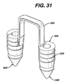
- the insertion member 600 may be molded into or affixed to the distal end of an implantation member 20, thereby forming a unitary structure as seen in FIG. 31 and FIG. 32.
- the insertion member 600 may be mounted to the distal end of an implantation member 520 in a conventional manner by gluing, cementing, mechanical fastening, friction fit, and the like and equivalent thereof.
- fixation member 500 of the present invention are used to affix a matrix to bone in the following manner.
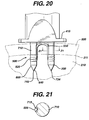
- the implantation members 520 of a fixation device 500 are placed upon prongs 700 of an instrument 400 such that the leg members 556 are at least partially engaged in grooves 715 in first section 710 (see FIG. 21), and, intermediate sections 720 of pin members 700 are engaged in passages 535 of implantation members 520, while pin members 730 extend out from the distal ends of the implantation members 520.
- insertion members 600 are placed over the pin members 730, such that the pin members 730 are engaged in passages 660, and such that the pointed piercing ends 734 extend beyond the distal ends 640 of the insertion member 660.
- the tool 400 and the assembly consisting of fixation device 500 and insertion member 600 is placed over a tissue matrix 220 placed upon a bone 210.
- the piercing points are then pressed through matrix 220 to contact the surface 211 of bone 210.
- a slap-hammer section of instrument 400 is engaged to drive the piercing points 734, insertion members 600 and implantation members 520 into the bone 210 as bore holes 200 are formed in the bone.
- the instrument 400 is then withdrawn proximately, thereby removing the intermediate sections 720 of prongs 700 from the implantation members 520 and the pin members 730 from the insertion members 600, leaving the insertion members 600 and the implantation members 520 securely in the bone (as seen in FIG. 20).
- fixation devices of the present invention It is particularly preferred to use conventional remote visualization surgical procedures when inserting the fixation devices of the present invention. For example, inserting a scope through a trocar cannula into the joint or body cavity , while insufflating the body cavity or joint.
- the insertion members 600 will typically be made from a strong, hard, bioabsorbable material such that they can be driven into bone without fracturing or breaking.
- Examples of the types of materials which can be used to make the insertion member 600 include polylactic acid, tricalcium phosphate, calcium phosphate, tetracalcium phosphate and hydroxyapatite, and any copolymers, mixtures or blends thereof.
- the insertion member 600 assists in forming the bore holes 200 while protecting the implantation members 520.
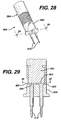
- FIGS. 22-23 illustrate a disposable distal end assembly 800 for an instrument 400 of the present invention.
- the distal end 415 of the shaft 405 of instrument 400 have screw threads 418, although other conventional detachable mounts may be used, for example a bayonet-type mount, locking levers and tabs, male and female mating sections, etc.
- the assembly 800 consists of housing 810 having proximal end 811 and distal end 817. Housing 810 is seen to have hollow cavity 815 therein. Cavity 815 is seen to be in communication with proximal end opening 812 and distal end openings 820. Member 810 is seen to have outer surface 822.
- Outer surface 822 is preferably knurled to facilitate the grasping and turning of the housing 810.
- Housing 810 is further seen to have distal end surface 825.
- the outer surface 822 is seen to have a tapered section 823 which tapers toward end face 825.
- Contained within cavity 815, on inner surface 818 are the screw threads 819.
- Assembly 800 is also seen to have driving pin members 830.
- Each driving pin member 830 is seen to have proximal disk member 832 mounted to proximal end 831, shaft section 834 and distal pointed end 838.
- Surrounding each opening 820 on the interior of the member 810 are the annular recesses 840.
- the assembly 800 is mounted to the distal end 415 of the instrument 400 in the following manner.
- the pins 830 are inserted into cavity 815 and through openings 820 such that the shafts 834 and distal piercing points 838 extend through end face 825, and the disk members 832 are contained within the annular recesses 840. Then, the housing 810 is mounted upon the threads of distal end 415 such that threads 418 engage mating threads 819, and screwed further such that the proximal end surfaces 833 of the disk members 832 are in contact with the distal end face 416 of distal end 415. After use in a surgical procedure, the assembly 800 is removed and discarded. A new sterile assembly 800 is utilized with a cleaned and sterilized instrument 400 for each new procedure.
- a disposable end assembly 900 for mounting to an insertion instrument 250 is illustrated.
- the insertion member 250 is seen to have distal end 264, having endface 265 and screw threads 266.
- the assembly 900 is seen to have housing 950.
- Housing 950 has proximal end 952 and distal end 956 and exterior surface 954.
- the exterior surface 954 is seen to have optional knurling, and distal tapered section 957 tapering into plate member 960. Extending from distal end 956 is the plate member 960.
- Plate member 960 is seen to have distal surface 962.
- Housing 950 is seen to have internal cavity 955.
- Housing 950 is also seen to have proximal opening 951 in communication with cavity 955 and distal openings 970 also in communication therewith. Housing 950 is seen to have internal screw threads 959 extending from internal surface 958. Also contained within the interior of housing 950 in the distal end 956 is the recessed groove 980. Assembly 900 is mounted to the distal end 264 of instrument 250 in the following manner. Pins 910 are inserted through cavity 950 and openings 970 such that proximal members 922 are engaged in groove 980. Sections 920 and 930 of pins 910 extend through openings 970. Sections 920 are seen to have grooves 925.
- the housing 950 is screwed on to distal end 264 such that the threads 266 engage the mating internal threads 959 of housing 950.
- the housing is tightened until the distal end surface 265 of the distal end 264 engages the top surfaces 923 of members 922.
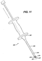
- FIG. 33 A novel combination slap-hammer and insertion instrument 1000 useful to mount the fixation devices of the present invention in bone is illustrated in FIG. 33.
- the instrument 1000 is seen to have a hammer handle 1010 slidably mounted to a hammer slide rod 1040.
- the hammer handle 1010 is seen to have proximal end 1012 and distal end 1014.
- the handle is further seen to have curved handle surface 1015 and proximal flange 1017 and distal flange 1019. Adjacent to the proximal flange 1017 is the proximal flange surface 1022, while adjacent to the distal flange 1019 is the distal flange surface 1020.
- Hammer handle 1010 is seen to have longitudinal passage 1030.
- the handle 1010 is further seen to have proximal opening 1032, distal opening 1034, both of which communicate with the longitudinal passage 1030.
- the handle 1010 is slidably mounted to the hammer slide rod 1040.
- Slide rod 1040 is seen to have proximal threaded end 1042 and distal threaded end 1044.
- Mounted to the proximal threaded end 1042 is the proximal knurled nut 1050.
- Rod 1040 is mounted at the distal threaded end 1044 to the distal knurled coupling 1060 having internal threads 1062.
- the hammer slide rod 1040 is further seen to have longitudinal axis 1070.
- the movement of the hammer member 1010 is seen to be constrained or limited along rod 1040 when shoulder 1036 contacts nut 1050 and when distal flange surface 1020 contacts proximal end 1061 of coupling 1060.
- the instrument 1010 is further seen to have a mounting member 1200 having first end 1210 and second end 1220.
- the mounting member 1200 is seen to have top curved side 1230 and bottom side 1240. Mounted to the top curved side 1230 adjacent to second end 1220 is the hammer connector 1250.
- Hammer connector 1250 is a cylindrical member having a threaded end 1252. Threaded end 1252 engages screw threads 1062 in distal end 1064 of coupling member 1060 for mounting the hammer handle 1010 and the hammer slide rod 1040 to the mounting member 1200 in an angulated manner as shown. Adjacent to end 1210 is the mounting rod passage 1215, having proximal end 1216 which extends through mounting member 1200. Extending transversely through end 1210 into the passage 1215 is the transverse threaded screw opening 1217 for receiving retaining screw 1219. Rotatably mounted in the mounting rod passage 1215, is the mounting rod 1110. Mounting rod 1110 is seen to have proximal screw threaded end 1112 and distal end 1120.
- the diameter of threaded end 1112 is less than the diameter of the rod 1110.
- Distal end 1120 is seen to have the angulated section 1125.
- Angulated section 1125 is seen to have longitudinal axis 1130 which is coincident with and/or parallel to longitudinal axis 1070.
- the mounting rod 1110 is seen to have longitudinal axis 1111.
- Adjacent to distal end 1120 is the screw threaded mounting section 1122.
- Disposable end assemblies 800 and 900 may be mounted to threaded end 1122.
- the rod 1110 is maintained is a fixed angular spatial position with respect to the mounting member 1200 by tightening set screw 1219, but is rotatable within the passage 1215 by loosening set screw 1219.
- Rod 1110 is fixed in place with respect to up and down motion with respect to member 1200 by the mounting top nut 1119 mounted to the proximal end 1112, and by an internal shoulder (not shown) projecting into passage 1215 just distal to proximal end 1216.
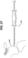
- the unique angulation provided by the instrument 1000 of the present invention provides the orthopedic surgeon with easier access with minimal incision when either tapping holes into a femur 1250 or inserting fixation devices as described herein. As seen in FIG.
- instrument 1100 provides for these advantages.
- the instruments 1100 are used to insert the fixation devices and combinations previously described herein using the procedures as described herein.
- the degree of angulation of the longitudinal axis 1130 of the angulated section 1125 and the longitudinal axis 1070 hammer slide rod 1040 with respect to longitudinal axis 1111 will be sufficient to provide effective access to the interior of a knee with minimal length incisions and minimal displacement of the parts of the knee.
- the angle may typically vary from O degrees to 50 degrees, more preferably from 20 degrees to 30 degrees.
- fixation devices of the present invention and the combination of the fixation devices with insertion members, and methods of using such devices and combinations, of the present invention have many advantages.
- the advantages include providing a fast and routine way to fixate a matrix of tissue engineered tissue or other tissue.
- the fixation devices and combination because they eliminate the need for suture knot tying, can be utilized in arthroscopic surgical procedures that require a minimum of surgical incisions and thus greatly reduce patient morbidity.
- the fixation devices and combination have been demonstrated to provide excellent matrix fixation without damaging the surrounding normal cartilaginous tissue, unlike the conventional fixation of chondral defect matrices with traditional suture that must be passed through (and thus damage) the surrounding tissue.
- the instruments of the present invention provide for a reusable section, and a distal disposable section that can be discarded.
Landscapes
- Health & Medical Sciences (AREA)
- Surgery (AREA)
- Life Sciences & Earth Sciences (AREA)
- Heart & Thoracic Surgery (AREA)
- Molecular Biology (AREA)
- Veterinary Medicine (AREA)
- Engineering & Computer Science (AREA)
- Biomedical Technology (AREA)
- Public Health (AREA)
- Medical Informatics (AREA)
- Nuclear Medicine, Radiotherapy & Molecular Imaging (AREA)
- Animal Behavior & Ethology (AREA)
- General Health & Medical Sciences (AREA)
- Rheumatology (AREA)
- Orthopedic Medicine & Surgery (AREA)
- Surgical Instruments (AREA)
- Prostheses (AREA)
Abstract
Description
Section 273 is seen to have a greater cross-sectional dimension than distal section 275 such that the entire section 275 is insertable into
FIGS. 5 and 6, the
Gross macroscopic assessment of the joints demonstrated that all four matrices held by the graft fixation device of the present invention were fully intact. However, all four matrices held by sutures alone were only partially intact with, on average, approximately 30% of the sutures broken on any given matrix.
Claims (6)
- An instrument for inserting a graft fixation device into bone, said instrument comprising:wherein the longitudinal axis of the slide rod is parallel to the longitudinal axis of the angulated distal end of the mounting rod.a mounting member having a first end, an opposed second end, a top and a bottom;an elongated slide rod member having a proximal end and a distal end and an outer surface and a longitudinal axis, wherein the distal end of the slide rod is mounted to the first end of the mounting rod such that the longitudinal axis of the mounting rod is angulated at an acute angle with respect to the mounting member;a hammer handle member having a distal end, a proximal end, an outer surface, a first flange member extending from the proximal end, a second flange member extending from the distal end, an inner passage therethrough and a longitudinal axis, wherein the hammer handle is slidably mounted to the slide rod member;a mounting rod having a proximal end and an angulated distal end, wherein the angulated distal end has a longitudinal axis, wherein the proximal end of the mounting rod is mounted to the second end of the mounting member; and,a pair of spaced apart prongs extending longitudinally from the distal end of the mounting rod,
- The instrument of claim 1 further comprising an inner shoulder extending into the inner passage of the hammer handle.
- The instrument of claim 1, wherein the mounting rod additionally comprises a screw threaded distal end, and a housing having an inner cavity and inner screw threads mounted to said threaded distal end, and the prongs extend out from said housing.
- The instrument of claim 1 wherein the mounting rod is rotatably mounted to the mounting member.
- The instrument of claim 1 wherein the mounting member has a threaded member mounted thereto at an angle for engaging a first end of a threaded coupling member, and wherein the distal end of the slide member is threaded and engages a second end of the coupling member.
- The instrument of claim 1 wherein the longitudinal axis of the slide rod is coincident with the longitudinal axis of the angulated distal end.
Applications Claiming Priority (2)
| Application Number | Priority Date | Filing Date | Title |
|---|---|---|---|
| US09/793,216 US6423073B2 (en) | 1999-07-23 | 2001-02-26 | Instrument for inserting graft fixation device |
| US793216 | 2001-02-26 |
Publications (3)
| Publication Number | Publication Date |
|---|---|
| EP1234545A2 true EP1234545A2 (en) | 2002-08-28 |
| EP1234545A3 EP1234545A3 (en) | 2003-01-15 |
| EP1234545B1 EP1234545B1 (en) | 2008-05-28 |
Family
ID=25159404
Family Applications (1)
| Application Number | Title | Priority Date | Filing Date |
|---|---|---|---|
| EP02251291A Expired - Lifetime EP1234545B1 (en) | 2001-02-26 | 2002-02-25 | Instrument for inserting graft fixation device |
Country Status (6)
| Country | Link |
|---|---|
| US (1) | US6423073B2 (en) |
| EP (1) | EP1234545B1 (en) |
| JP (1) | JP4223220B2 (en) |
| AU (1) | AU784747B2 (en) |
| CA (1) | CA2372734C (en) |
| DE (1) | DE60226797D1 (en) |
Cited By (2)
| Publication number | Priority date | Publication date | Assignee | Title |
|---|---|---|---|---|
| EP2345389A1 (en) * | 2010-01-18 | 2011-07-20 | Karl Storz GmbH & Co. KG | Insertion instrument for wrapping a blocking element |
| US8828004B2 (en) | 2008-11-06 | 2014-09-09 | Shu Nakamura | Surgical chisel |
Families Citing this family (298)
| Publication number | Priority date | Publication date | Assignee | Title |
|---|---|---|---|---|
| US20020095157A1 (en) | 1999-07-23 | 2002-07-18 | Bowman Steven M. | Graft fixation device combination |
| US6179840B1 (en) | 1999-07-23 | 2001-01-30 | Ethicon, Inc. | Graft fixation device and method |
| US11229472B2 (en) | 2001-06-12 | 2022-01-25 | Cilag Gmbh International | Modular battery powered handheld surgical instrument with multiple magnetic position sensors |
| WO2003007805A2 (en) | 2001-07-16 | 2003-01-30 | Depuy Products, Inc. | Cartilage repair apparatus and method |
| AU2002354911B2 (en) | 2001-07-16 | 2007-08-30 | Depuy Products, Inc. | Meniscus regeneration device and method |
| WO2003007839A2 (en) * | 2001-07-16 | 2003-01-30 | Depuy Products, Inc. | Devices form naturally occurring biologically derived |
| US7819918B2 (en) | 2001-07-16 | 2010-10-26 | Depuy Products, Inc. | Implantable tissue repair device |
| JP2005515802A (en) | 2001-07-16 | 2005-06-02 | デピュイ・プロダクツ・インコーポレイテッド | Hybrid / Synthetic Porous Extracellular Matrix Support Skeleton |
| US8025896B2 (en) | 2001-07-16 | 2011-09-27 | Depuy Products, Inc. | Porous extracellular matrix scaffold and method |
| US7163563B2 (en) | 2001-07-16 | 2007-01-16 | Depuy Products, Inc. | Unitary surgical device and method |
| EP1416886A4 (en) * | 2001-07-16 | 2007-04-18 | Depuy Products Inc | Cartilage repair and regeneration scaffold and method |
| US20120145765A1 (en) | 2002-06-25 | 2012-06-14 | Peterson James A | Mechanical method and apparatus for bilateral tissue fastening |
| US7087064B1 (en) * | 2002-10-15 | 2006-08-08 | Advanced Cardiovascular Systems, Inc. | Apparatuses and methods for heart valve repair |
| US7404824B1 (en) | 2002-11-15 | 2008-07-29 | Advanced Cardiovascular Systems, Inc. | Valve aptation assist device |
| US7485143B2 (en) | 2002-11-15 | 2009-02-03 | Abbott Cardiovascular Systems Inc. | Apparatuses and methods for heart valve repair |
| US7331972B1 (en) | 2002-11-15 | 2008-02-19 | Abbott Cardiovascular Systems Inc. | Heart valve chord cutter |
| US9149602B2 (en) | 2005-04-22 | 2015-10-06 | Advanced Cardiovascular Systems, Inc. | Dual needle delivery system |
| US8187324B2 (en) | 2002-11-15 | 2012-05-29 | Advanced Cardiovascular Systems, Inc. | Telescoping apparatus for delivering and adjusting a medical device in a vessel |
| US7981152B1 (en) | 2004-12-10 | 2011-07-19 | Advanced Cardiovascular Systems, Inc. | Vascular delivery system for accessing and delivering devices into coronary sinus and other vascular sites |
| US7794408B2 (en) | 2003-03-28 | 2010-09-14 | Ethicon, Inc. | Tissue collection device and methods |
| US7387633B2 (en) * | 2003-04-04 | 2008-06-17 | Osteomed L.P. | Cranial flap fixation system and method |
| US7611473B2 (en) * | 2003-09-11 | 2009-11-03 | Ethicon, Inc. | Tissue extraction and maceration device |
| US8034003B2 (en) | 2003-09-11 | 2011-10-11 | Depuy Mitek, Inc. | Tissue extraction and collection device |
| US7998112B2 (en) | 2003-09-30 | 2011-08-16 | Abbott Cardiovascular Systems Inc. | Deflectable catheter assembly and method of making same |
| US7766920B2 (en) * | 2003-11-26 | 2010-08-03 | Synthes Usa, Llc | Cannulated fastener system |
| US8182501B2 (en) | 2004-02-27 | 2012-05-22 | Ethicon Endo-Surgery, Inc. | Ultrasonic surgical shears and method for sealing a blood vessel using same |
| US7604643B2 (en) * | 2004-04-06 | 2009-10-20 | Synthes Usa, Llc | Adjustable tool for cannulated fasteners |
| US20050240197A1 (en) * | 2004-04-23 | 2005-10-27 | Kmiec Stanley J Jr | Device and method for inserting, positioning and removing an implant |
| US7569233B2 (en) | 2004-05-04 | 2009-08-04 | Depuy Products, Inc. | Hybrid biologic-synthetic bioabsorbable scaffolds |
| US20060064108A1 (en) * | 2004-09-09 | 2006-03-23 | Blaylock Jeffrey C | Tibial sizing apparatus and method |
| EP3162309B1 (en) | 2004-10-08 | 2022-10-26 | Ethicon LLC | Ultrasonic surgical instrument |
| US7749250B2 (en) | 2006-02-03 | 2010-07-06 | Biomet Sports Medicine, Llc | Soft tissue repair assembly and associated method |
| US8298262B2 (en) | 2006-02-03 | 2012-10-30 | Biomet Sports Medicine, Llc | Method for tissue fixation |
| US8118836B2 (en) | 2004-11-05 | 2012-02-21 | Biomet Sports Medicine, Llc | Method and apparatus for coupling soft tissue to a bone |
| US8137382B2 (en) | 2004-11-05 | 2012-03-20 | Biomet Sports Medicine, Llc | Method and apparatus for coupling anatomical features |
| US9017381B2 (en) | 2007-04-10 | 2015-04-28 | Biomet Sports Medicine, Llc | Adjustable knotless loops |
| US7905904B2 (en) | 2006-02-03 | 2011-03-15 | Biomet Sports Medicine, Llc | Soft tissue repair device and associated methods |
| US7909851B2 (en) | 2006-02-03 | 2011-03-22 | Biomet Sports Medicine, Llc | Soft tissue repair device and associated methods |
| US8088130B2 (en) | 2006-02-03 | 2012-01-03 | Biomet Sports Medicine, Llc | Method and apparatus for coupling soft tissue to a bone |
| US8128658B2 (en) | 2004-11-05 | 2012-03-06 | Biomet Sports Medicine, Llc | Method and apparatus for coupling soft tissue to bone |
| US7658751B2 (en) | 2006-09-29 | 2010-02-09 | Biomet Sports Medicine, Llc | Method for implanting soft tissue |
| US8361113B2 (en) | 2006-02-03 | 2013-01-29 | Biomet Sports Medicine, Llc | Method and apparatus for coupling soft tissue to a bone |
| US8840645B2 (en) | 2004-11-05 | 2014-09-23 | Biomet Sports Medicine, Llc | Method and apparatus for coupling soft tissue to a bone |
| US9801708B2 (en) | 2004-11-05 | 2017-10-31 | Biomet Sports Medicine, Llc | Method and apparatus for coupling soft tissue to a bone |
| US8303604B2 (en) | 2004-11-05 | 2012-11-06 | Biomet Sports Medicine, Llc | Soft tissue repair device and method |
| US8998949B2 (en) | 2004-11-09 | 2015-04-07 | Biomet Sports Medicine, Llc | Soft tissue conduit device |
| US7354627B2 (en) | 2004-12-22 | 2008-04-08 | Depuy Products, Inc. | Method for organizing the assembly of collagen fibers and compositions formed therefrom |
| WO2006088684A1 (en) * | 2005-02-17 | 2006-08-24 | Zimmer Technology, Inc. | Tibial trialing assembly and method of trialing a tibial implant |
| US7595062B2 (en) | 2005-07-28 | 2009-09-29 | Depuy Products, Inc. | Joint resurfacing orthopaedic implant and associated method |
| US20070191713A1 (en) | 2005-10-14 | 2007-08-16 | Eichmann Stephen E | Ultrasonic device for cutting and coagulating |
| US7371260B2 (en) * | 2005-10-26 | 2008-05-13 | Biomet Sports Medicine, Inc. | Method and instrumentation for the preparation and transplantation of osteochondral allografts |
| US20070100351A1 (en) * | 2005-10-31 | 2007-05-03 | Deffenbaugh Daren L | Multiple suture anchor delivery device, suture anchor delivery kit and associated method |
| US20070100350A1 (en) * | 2005-10-31 | 2007-05-03 | Deffenbaugh Daren L | Suture anchor cartridge holder, suture anchor cartridge and associated method |
| US7621930B2 (en) | 2006-01-20 | 2009-11-24 | Ethicon Endo-Surgery, Inc. | Ultrasound medical instrument having a medical ultrasonic blade |
| US10517587B2 (en) | 2006-02-03 | 2019-12-31 | Biomet Sports Medicine, Llc | Method and apparatus for forming a self-locking adjustable loop |
| US8506597B2 (en) | 2011-10-25 | 2013-08-13 | Biomet Sports Medicine, Llc | Method and apparatus for interosseous membrane reconstruction |
| US8574235B2 (en) | 2006-02-03 | 2013-11-05 | Biomet Sports Medicine, Llc | Method for trochanteric reattachment |
| US8562645B2 (en) | 2006-09-29 | 2013-10-22 | Biomet Sports Medicine, Llc | Method and apparatus for forming a self-locking adjustable loop |
| US9149267B2 (en) | 2006-02-03 | 2015-10-06 | Biomet Sports Medicine, Llc | Method and apparatus for coupling soft tissue to a bone |
| US8562647B2 (en) | 2006-09-29 | 2013-10-22 | Biomet Sports Medicine, Llc | Method and apparatus for securing soft tissue to bone |
| US8251998B2 (en) | 2006-08-16 | 2012-08-28 | Biomet Sports Medicine, Llc | Chondral defect repair |
| US11259792B2 (en) | 2006-02-03 | 2022-03-01 | Biomet Sports Medicine, Llc | Method and apparatus for coupling anatomical features |
| US9078644B2 (en) | 2006-09-29 | 2015-07-14 | Biomet Sports Medicine, Llc | Fracture fixation device |
| US8652172B2 (en) | 2006-02-03 | 2014-02-18 | Biomet Sports Medicine, Llc | Flexible anchors for tissue fixation |
| US9538998B2 (en) | 2006-02-03 | 2017-01-10 | Biomet Sports Medicine, Llc | Method and apparatus for fracture fixation |
| US8936621B2 (en) | 2006-02-03 | 2015-01-20 | Biomet Sports Medicine, Llc | Method and apparatus for forming a self-locking adjustable loop |
| US8968364B2 (en) | 2006-02-03 | 2015-03-03 | Biomet Sports Medicine, Llc | Method and apparatus for fixation of an ACL graft |
| US8801783B2 (en) | 2006-09-29 | 2014-08-12 | Biomet Sports Medicine, Llc | Prosthetic ligament system for knee joint |
| US8652171B2 (en) | 2006-02-03 | 2014-02-18 | Biomet Sports Medicine, Llc | Method and apparatus for soft tissue fixation |
| US11311287B2 (en) | 2006-02-03 | 2022-04-26 | Biomet Sports Medicine, Llc | Method for tissue fixation |
| US8597327B2 (en) | 2006-02-03 | 2013-12-03 | Biomet Manufacturing, Llc | Method and apparatus for sternal closure |
| US8771352B2 (en) | 2011-05-17 | 2014-07-08 | Biomet Sports Medicine, Llc | Method and apparatus for tibial fixation of an ACL graft |
| US7572291B2 (en) * | 2006-03-28 | 2009-08-11 | Warsaw Orthopedic, Inc. | Osteochondral repair assembly including retracting spacer, kit and method |
| US8221423B2 (en) * | 2006-03-28 | 2012-07-17 | Warsaw Orthopedic, Inc. | Osteochondral plug graft harvesting instrument and kit |
| US8709094B2 (en) * | 2006-06-26 | 2014-04-29 | DePuy Synthes Products, LLC | Anti-adhesion sheet |
| CA2655197C (en) * | 2006-07-01 | 2014-02-18 | Opus Ksd Inc. | Tissue fasteners and related insertion devices, mechanisms, and methods |
| US11259794B2 (en) | 2006-09-29 | 2022-03-01 | Biomet Sports Medicine, Llc | Method for implanting soft tissue |
| US8672969B2 (en) | 2006-09-29 | 2014-03-18 | Biomet Sports Medicine, Llc | Fracture fixation device |
| US9918826B2 (en) | 2006-09-29 | 2018-03-20 | Biomet Sports Medicine, Llc | Scaffold for spring ligament repair |
| US8500818B2 (en) | 2006-09-29 | 2013-08-06 | Biomet Manufacturing, Llc | Knee prosthesis assembly with ligament link |
| US8114159B2 (en) | 2006-11-20 | 2012-02-14 | Depuy Spine, Inc. | Anterior spinal vessel protector |
| US7871440B2 (en) | 2006-12-11 | 2011-01-18 | Depuy Products, Inc. | Unitary surgical device and method |
| US12502169B2 (en) | 2007-01-16 | 2025-12-23 | Biomet Sports Medicine, Llc | Soft tissue repair device and associated methods |
| US8226675B2 (en) | 2007-03-22 | 2012-07-24 | Ethicon Endo-Surgery, Inc. | Surgical instruments |
| US8057498B2 (en) | 2007-11-30 | 2011-11-15 | Ethicon Endo-Surgery, Inc. | Ultrasonic surgical instrument blades |
| US20080234709A1 (en) | 2007-03-22 | 2008-09-25 | Houser Kevin L | Ultrasonic surgical instrument and cartilage and bone shaping blades therefor |
| US8911460B2 (en) | 2007-03-22 | 2014-12-16 | Ethicon Endo-Surgery, Inc. | Ultrasonic surgical instruments |
| US8142461B2 (en) | 2007-03-22 | 2012-03-27 | Ethicon Endo-Surgery, Inc. | Surgical instruments |
| US8257377B2 (en) | 2007-07-27 | 2012-09-04 | Ethicon Endo-Surgery, Inc. | Multiple end effectors ultrasonic surgical instruments |
| US8882791B2 (en) | 2007-07-27 | 2014-11-11 | Ethicon Endo-Surgery, Inc. | Ultrasonic surgical instruments |
| US8348967B2 (en) | 2007-07-27 | 2013-01-08 | Ethicon Endo-Surgery, Inc. | Ultrasonic surgical instruments |
| US8808319B2 (en) | 2007-07-27 | 2014-08-19 | Ethicon Endo-Surgery, Inc. | Surgical instruments |
| US8523889B2 (en) | 2007-07-27 | 2013-09-03 | Ethicon Endo-Surgery, Inc. | Ultrasonic end effectors with increased active length |
| US8512365B2 (en) | 2007-07-31 | 2013-08-20 | Ethicon Endo-Surgery, Inc. | Surgical instruments |
| US9044261B2 (en) | 2007-07-31 | 2015-06-02 | Ethicon Endo-Surgery, Inc. | Temperature controlled ultrasonic surgical instruments |
| US8252012B2 (en) | 2007-07-31 | 2012-08-28 | Ethicon Endo-Surgery, Inc. | Ultrasonic surgical instrument with modulator |
| US8430898B2 (en) | 2007-07-31 | 2013-04-30 | Ethicon Endo-Surgery, Inc. | Ultrasonic surgical instruments |
| US8303592B2 (en) * | 2007-10-05 | 2012-11-06 | Biomet Manufacturing Corp. | System for forming a tendon-bone graft |
| USD594983S1 (en) | 2007-10-05 | 2009-06-23 | Ethicon Endo-Surgery, Inc. | Handle assembly for surgical instrument |
| AU2008308606B2 (en) | 2007-10-05 | 2014-12-18 | Ethicon Endo-Surgery, Inc. | Ergonomic surgical instruments |
| US8322256B2 (en) * | 2007-10-05 | 2012-12-04 | Biomet Manufacturing Corp. | System for forming a tendon-bone graft |
| US10010339B2 (en) | 2007-11-30 | 2018-07-03 | Ethicon Llc | Ultrasonic surgical blades |
| US7901423B2 (en) | 2007-11-30 | 2011-03-08 | Ethicon Endo-Surgery, Inc. | Folded ultrasonic end effectors with increased active length |
| US8058771B2 (en) | 2008-08-06 | 2011-11-15 | Ethicon Endo-Surgery, Inc. | Ultrasonic device for cutting and coagulating with stepped output |
| US9089360B2 (en) | 2008-08-06 | 2015-07-28 | Ethicon Endo-Surgery, Inc. | Devices and techniques for cutting and coagulating tissue |
| US12245759B2 (en) | 2008-08-22 | 2025-03-11 | Biomet Sports Medicine, Llc | Method and apparatus for coupling soft tissue to bone |
| US12419632B2 (en) | 2008-08-22 | 2025-09-23 | Biomet Sports Medicine, Llc | Method and apparatus for coupling anatomical features |
| US8241298B2 (en) * | 2009-03-27 | 2012-08-14 | Depuy Mitek, Inc. | Methods and devices for delivering and affixing tissue scaffolds |
| US8308814B2 (en) | 2009-03-27 | 2012-11-13 | Depuy Mitek, Inc. | Methods and devices for preparing and implanting tissue scaffolds |
| US9700339B2 (en) | 2009-05-20 | 2017-07-11 | Ethicon Endo-Surgery, Inc. | Coupling arrangements and methods for attaching tools to ultrasonic surgical instruments |
| US20100305710A1 (en) | 2009-05-28 | 2010-12-02 | Biomet Manufacturing Corp. | Knee Prosthesis |
| US12096928B2 (en) | 2009-05-29 | 2024-09-24 | Biomet Sports Medicine, Llc | Method and apparatus for coupling soft tissue to a bone |
| US12551209B2 (en) | 2009-06-22 | 2026-02-17 | Biomet Sports Medicine, Llc | Method and apparatus for coupling soft tissue to a bone |
| US8334635B2 (en) | 2009-06-24 | 2012-12-18 | Ethicon Endo-Surgery, Inc. | Transducer arrangements for ultrasonic surgical instruments |
| US8461744B2 (en) | 2009-07-15 | 2013-06-11 | Ethicon Endo-Surgery, Inc. | Rotating transducer mount for ultrasonic surgical instruments |
| US8663220B2 (en) | 2009-07-15 | 2014-03-04 | Ethicon Endo-Surgery, Inc. | Ultrasonic surgical instruments |
| US9017326B2 (en) | 2009-07-15 | 2015-04-28 | Ethicon Endo-Surgery, Inc. | Impedance monitoring apparatus, system, and method for ultrasonic surgical instruments |
| US10441345B2 (en) | 2009-10-09 | 2019-10-15 | Ethicon Llc | Surgical generator for ultrasonic and electrosurgical devices |
| US9168054B2 (en) | 2009-10-09 | 2015-10-27 | Ethicon Endo-Surgery, Inc. | Surgical generator for ultrasonic and electrosurgical devices |
| USRE47996E1 (en) | 2009-10-09 | 2020-05-19 | Ethicon Llc | Surgical generator for ultrasonic and electrosurgical devices |
| US11090104B2 (en) | 2009-10-09 | 2021-08-17 | Cilag Gmbh International | Surgical generator for ultrasonic and electrosurgical devices |
| US10172669B2 (en) | 2009-10-09 | 2019-01-08 | Ethicon Llc | Surgical instrument comprising an energy trigger lockout |
| US9039695B2 (en) | 2009-10-09 | 2015-05-26 | Ethicon Endo-Surgery, Inc. | Surgical generator for ultrasonic and electrosurgical devices |
| US8961547B2 (en) | 2010-02-11 | 2015-02-24 | Ethicon Endo-Surgery, Inc. | Ultrasonic surgical instruments with moving cutting implement |
| US8531064B2 (en) | 2010-02-11 | 2013-09-10 | Ethicon Endo-Surgery, Inc. | Ultrasonically powered surgical instruments with rotating cutting implement |
| US8382782B2 (en) | 2010-02-11 | 2013-02-26 | Ethicon Endo-Surgery, Inc. | Ultrasonic surgical instruments with partially rotating blade and fixed pad arrangement |
| US8951272B2 (en) | 2010-02-11 | 2015-02-10 | Ethicon Endo-Surgery, Inc. | Seal arrangements for ultrasonically powered surgical instruments |
| US8486096B2 (en) | 2010-02-11 | 2013-07-16 | Ethicon Endo-Surgery, Inc. | Dual purpose surgical instrument for cutting and coagulating tissue |
| US8419759B2 (en) | 2010-02-11 | 2013-04-16 | Ethicon Endo-Surgery, Inc. | Ultrasonic surgical instrument with comb-like tissue trimming device |
| US9259234B2 (en) | 2010-02-11 | 2016-02-16 | Ethicon Endo-Surgery, Llc | Ultrasonic surgical instruments with rotatable blade and hollow sheath arrangements |
| US8469981B2 (en) | 2010-02-11 | 2013-06-25 | Ethicon Endo-Surgery, Inc. | Rotatable cutting implement arrangements for ultrasonic surgical instruments |
| US8579928B2 (en) | 2010-02-11 | 2013-11-12 | Ethicon Endo-Surgery, Inc. | Outer sheath and blade arrangements for ultrasonic surgical instruments |
| US8323302B2 (en) | 2010-02-11 | 2012-12-04 | Ethicon Endo-Surgery, Inc. | Methods of using ultrasonically powered surgical instruments with rotatable cutting implements |
| GB2480498A (en) | 2010-05-21 | 2011-11-23 | Ethicon Endo Surgery Inc | Medical device comprising RF circuitry |
| US8795327B2 (en) | 2010-07-22 | 2014-08-05 | Ethicon Endo-Surgery, Inc. | Electrosurgical instrument with separate closure and cutting members |
| US9192431B2 (en) | 2010-07-23 | 2015-11-24 | Ethicon Endo-Surgery, Inc. | Electrosurgical cutting and sealing instrument |
| US8888809B2 (en) | 2010-10-01 | 2014-11-18 | Ethicon Endo-Surgery, Inc. | Surgical instrument with jaw member |
| US8979890B2 (en) | 2010-10-01 | 2015-03-17 | Ethicon Endo-Surgery, Inc. | Surgical instrument with jaw member |
| US8968293B2 (en) | 2011-04-12 | 2015-03-03 | Covidien Lp | Systems and methods for calibrating power measurements in an electrosurgical generator |
| US12329373B2 (en) | 2011-05-02 | 2025-06-17 | Biomet Sports Medicine, Llc | Method and apparatus for soft tissue fixation |
| US8721648B2 (en) | 2011-05-13 | 2014-05-13 | Biomet Manufacturing, Llc | Microfracture pick for femoral head |
| US9259265B2 (en) | 2011-07-22 | 2016-02-16 | Ethicon Endo-Surgery, Llc | Surgical instruments for tensioning tissue |
| USD700699S1 (en) | 2011-08-23 | 2014-03-04 | Covidien Ag | Handle for portable surgical device |
| US9421060B2 (en) | 2011-10-24 | 2016-08-23 | Ethicon Endo-Surgery, Llc | Litz wire battery powered device |
| USD687549S1 (en) | 2011-10-24 | 2013-08-06 | Ethicon Endo-Surgery, Inc. | Surgical instrument |
| US12582395B2 (en) | 2011-11-03 | 2026-03-24 | Biomet Sports Medicine, Llc | Method and apparatus for forming a self-locking adjustable loop |
| US9357991B2 (en) | 2011-11-03 | 2016-06-07 | Biomet Sports Medicine, Llc | Method and apparatus for stitching tendons |
| WO2013070686A1 (en) * | 2011-11-08 | 2013-05-16 | Boston Scientific Scimed, Inc. | Handle assembly for a left atrial appendage occlusion device |
| US9314241B2 (en) | 2011-11-10 | 2016-04-19 | Biomet Sports Medicine, Llc | Apparatus for coupling soft tissue to a bone |
| US9370350B2 (en) | 2011-11-10 | 2016-06-21 | Biomet Sports Medicine, Llc | Apparatus for coupling soft tissue to a bone |
| US9381013B2 (en) | 2011-11-10 | 2016-07-05 | Biomet Sports Medicine, Llc | Method for coupling soft tissue to a bone |
| JP6165780B2 (en) | 2012-02-10 | 2017-07-19 | エシコン・エンド−サージェリィ・インコーポレイテッドEthicon Endo−Surgery,Inc. | Robot-controlled surgical instrument |
| US9241731B2 (en) | 2012-04-09 | 2016-01-26 | Ethicon Endo-Surgery, Inc. | Rotatable electrical connection for ultrasonic surgical instruments |
| US9237921B2 (en) | 2012-04-09 | 2016-01-19 | Ethicon Endo-Surgery, Inc. | Devices and techniques for cutting and coagulating tissue |
| US9439668B2 (en) | 2012-04-09 | 2016-09-13 | Ethicon Endo-Surgery, Llc | Switch arrangements for ultrasonic surgical instruments |
| US9226766B2 (en) | 2012-04-09 | 2016-01-05 | Ethicon Endo-Surgery, Inc. | Serial communication protocol for medical device |
| US9724118B2 (en) | 2012-04-09 | 2017-08-08 | Ethicon Endo-Surgery, Llc | Techniques for cutting and coagulating tissue for ultrasonic surgical instruments |
| US20140005705A1 (en) | 2012-06-29 | 2014-01-02 | Ethicon Endo-Surgery, Inc. | Surgical instruments with articulating shafts |
| US9351754B2 (en) | 2012-06-29 | 2016-05-31 | Ethicon Endo-Surgery, Llc | Ultrasonic surgical instruments with distally positioned jaw assemblies |
| US9820768B2 (en) | 2012-06-29 | 2017-11-21 | Ethicon Llc | Ultrasonic surgical instruments with control mechanisms |
| US9393037B2 (en) | 2012-06-29 | 2016-07-19 | Ethicon Endo-Surgery, Llc | Surgical instruments with articulating shafts |
| US20140005702A1 (en) | 2012-06-29 | 2014-01-02 | Ethicon Endo-Surgery, Inc. | Ultrasonic surgical instruments with distally positioned transducers |
| US9326788B2 (en) | 2012-06-29 | 2016-05-03 | Ethicon Endo-Surgery, Llc | Lockout mechanism for use with robotic electrosurgical device |
| US9226767B2 (en) | 2012-06-29 | 2016-01-05 | Ethicon Endo-Surgery, Inc. | Closed feedback control for electrosurgical device |
| US9283045B2 (en) | 2012-06-29 | 2016-03-15 | Ethicon Endo-Surgery, Llc | Surgical instruments with fluid management system |
| US9408622B2 (en) | 2012-06-29 | 2016-08-09 | Ethicon Endo-Surgery, Llc | Surgical instruments with articulating shafts |
| US9198714B2 (en) | 2012-06-29 | 2015-12-01 | Ethicon Endo-Surgery, Inc. | Haptic feedback devices for surgical robot |
| WO2014052181A1 (en) | 2012-09-28 | 2014-04-03 | Ethicon Endo-Surgery, Inc. | Multi-function bi-polar forceps |
| US10201365B2 (en) | 2012-10-22 | 2019-02-12 | Ethicon Llc | Surgeon feedback sensing and display methods |
| US9095367B2 (en) | 2012-10-22 | 2015-08-04 | Ethicon Endo-Surgery, Inc. | Flexible harmonic waveguides/blades for surgical instruments |
| US20140135804A1 (en) | 2012-11-15 | 2014-05-15 | Ethicon Endo-Surgery, Inc. | Ultrasonic and electrosurgical devices |
| US20150297247A1 (en) | 2012-12-08 | 2015-10-22 | Kevin Seex | Surgical Tool |
| US9237894B2 (en) | 2013-01-31 | 2016-01-19 | Depuy Mitek, Llc | Methods and devices for forming holes in bone to stimulate bone growth |
| US9232943B2 (en) * | 2013-01-31 | 2016-01-12 | Opus Ksd Inc. | Delivering bioabsorbable fasteners |
| US9757119B2 (en) | 2013-03-08 | 2017-09-12 | Biomet Sports Medicine, Llc | Visual aid for identifying suture limbs arthroscopically |
| US9918827B2 (en) | 2013-03-14 | 2018-03-20 | Biomet Sports Medicine, Llc | Scaffold for spring ligament repair |
| US10226273B2 (en) | 2013-03-14 | 2019-03-12 | Ethicon Llc | Mechanical fasteners for use with surgical energy devices |
| US9241728B2 (en) | 2013-03-15 | 2016-01-26 | Ethicon Endo-Surgery, Inc. | Surgical instrument with multiple clamping mechanisms |
| US9814514B2 (en) | 2013-09-13 | 2017-11-14 | Ethicon Llc | Electrosurgical (RF) medical instruments for cutting and coagulating tissue |
| US9265926B2 (en) | 2013-11-08 | 2016-02-23 | Ethicon Endo-Surgery, Llc | Electrosurgical devices |
| GB2521228A (en) | 2013-12-16 | 2015-06-17 | Ethicon Endo Surgery Inc | Medical device |
| GB2521229A (en) | 2013-12-16 | 2015-06-17 | Ethicon Endo Surgery Inc | Medical device |
| EP3082632A4 (en) | 2013-12-20 | 2018-01-10 | Crossroads Extremity Systems, LLC | Polyaxial locking hole |
| US10136886B2 (en) | 2013-12-20 | 2018-11-27 | Biomet Sports Medicine, Llc | Knotless soft tissue devices and techniques |
| US9795436B2 (en) | 2014-01-07 | 2017-10-24 | Ethicon Llc | Harvesting energy from a surgical generator |
| US9554854B2 (en) | 2014-03-18 | 2017-01-31 | Ethicon Endo-Surgery, Llc | Detecting short circuits in electrosurgical medical devices |
| US10092310B2 (en) | 2014-03-27 | 2018-10-09 | Ethicon Llc | Electrosurgical devices |
| US10463421B2 (en) | 2014-03-27 | 2019-11-05 | Ethicon Llc | Two stage trigger, clamp and cut bipolar vessel sealer |
| US9737355B2 (en) | 2014-03-31 | 2017-08-22 | Ethicon Llc | Controlling impedance rise in electrosurgical medical devices |
| US9913680B2 (en) | 2014-04-15 | 2018-03-13 | Ethicon Llc | Software algorithms for electrosurgical instruments |
| US9844377B2 (en) | 2014-04-25 | 2017-12-19 | Incisive Surgical, Inc. | Method and apparatus for wound closure with sequential tissue positioning and retention |
| US9615822B2 (en) | 2014-05-30 | 2017-04-11 | Biomet Sports Medicine, Llc | Insertion tools and method for soft anchor |
| US9700291B2 (en) | 2014-06-03 | 2017-07-11 | Biomet Sports Medicine, Llc | Capsule retractor |
| US9700333B2 (en) | 2014-06-30 | 2017-07-11 | Ethicon Llc | Surgical instrument with variable tissue compression |
| JP2017529886A (en) | 2014-07-10 | 2017-10-12 | クロスローズ エクストリミティ システムズ リミテッド ライアビリティ カンパニー | Bone implant and means of insertion |
| US11202626B2 (en) | 2014-07-10 | 2021-12-21 | Crossroads Extremity Systems, Llc | Bone implant with means for multi directional force and means of insertion |
| US10285724B2 (en) | 2014-07-31 | 2019-05-14 | Ethicon Llc | Actuation mechanisms and load adjustment assemblies for surgical instruments |
| US10039543B2 (en) | 2014-08-22 | 2018-08-07 | Biomet Sports Medicine, Llc | Non-sliding soft anchor |
| CA3161026A1 (en) | 2014-09-17 | 2016-03-24 | Canary Medical Inc. | Devices, systems and methods for using and monitoring medical devices |
| US10639092B2 (en) | 2014-12-08 | 2020-05-05 | Ethicon Llc | Electrode configurations for surgical instruments |
| US10568616B2 (en) | 2014-12-17 | 2020-02-25 | Howmedica Osteonics Corp. | Instruments and methods of soft tissue fixation |
| US10159524B2 (en) | 2014-12-22 | 2018-12-25 | Ethicon Llc | High power battery powered RF amplifier topology |
| US10245095B2 (en) | 2015-02-06 | 2019-04-02 | Ethicon Llc | Electrosurgical instrument with rotation and articulation mechanisms |
| US9955980B2 (en) | 2015-02-24 | 2018-05-01 | Biomet Sports Medicine, Llc | Anatomic soft tissue repair |
| US10342602B2 (en) | 2015-03-17 | 2019-07-09 | Ethicon Llc | Managing tissue treatment |
| US10321950B2 (en) | 2015-03-17 | 2019-06-18 | Ethicon Llc | Managing tissue treatment |
| US10595929B2 (en) | 2015-03-24 | 2020-03-24 | Ethicon Llc | Surgical instruments with firing system overload protection mechanisms |
| US9974534B2 (en) | 2015-03-31 | 2018-05-22 | Biomet Sports Medicine, Llc | Suture anchor with soft anchor of electrospun fibers |
| US10524912B2 (en) * | 2015-04-02 | 2020-01-07 | Abbott Cardiovascular Systems, Inc. | Tissue fixation devices and methods |
| US10314638B2 (en) | 2015-04-07 | 2019-06-11 | Ethicon Llc | Articulating radio frequency (RF) tissue seal with articulating state sensing |
| US10034684B2 (en) | 2015-06-15 | 2018-07-31 | Ethicon Llc | Apparatus and method for dissecting and coagulating tissue |
| US11020140B2 (en) | 2015-06-17 | 2021-06-01 | Cilag Gmbh International | Ultrasonic surgical blade for use with ultrasonic surgical instruments |
| US10765470B2 (en) | 2015-06-30 | 2020-09-08 | Ethicon Llc | Surgical system with user adaptable techniques employing simultaneous energy modalities based on tissue parameters |
| US10034704B2 (en) | 2015-06-30 | 2018-07-31 | Ethicon Llc | Surgical instrument with user adaptable algorithms |
| US10357303B2 (en) | 2015-06-30 | 2019-07-23 | Ethicon Llc | Translatable outer tube for sealing using shielded lap chole dissector |
| US11129669B2 (en) | 2015-06-30 | 2021-09-28 | Cilag Gmbh International | Surgical system with user adaptable techniques based on tissue type |
| US11051873B2 (en) | 2015-06-30 | 2021-07-06 | Cilag Gmbh International | Surgical system with user adaptable techniques employing multiple energy modalities based on tissue parameters |
| US10898256B2 (en) | 2015-06-30 | 2021-01-26 | Ethicon Llc | Surgical system with user adaptable techniques based on tissue impedance |
| US10154852B2 (en) | 2015-07-01 | 2018-12-18 | Ethicon Llc | Ultrasonic surgical blade with improved cutting and coagulation features |
| US20170000533A1 (en) | 2015-07-02 | 2017-01-05 | First Ray, LLC | Compression implants, instruments and methods |
| CN107847254B (en) | 2015-07-13 | 2021-06-18 | 汇聚义肢系统有限责任公司 | Plates with Dynamic Elements |
| US10687884B2 (en) | 2015-09-30 | 2020-06-23 | Ethicon Llc | Circuits for supplying isolated direct current (DC) voltage to surgical instruments |
| US10595930B2 (en) | 2015-10-16 | 2020-03-24 | Ethicon Llc | Electrode wiping surgical device |
| US10959771B2 (en) | 2015-10-16 | 2021-03-30 | Ethicon Llc | Suction and irrigation sealing grasper |
| US10702290B2 (en) | 2015-11-02 | 2020-07-07 | First Ray, LLC | Orthopedic fastener, retainer, and guide |
| US10179022B2 (en) | 2015-12-30 | 2019-01-15 | Ethicon Llc | Jaw position impedance limiter for electrosurgical instrument |
| US10959806B2 (en) | 2015-12-30 | 2021-03-30 | Ethicon Llc | Energized medical device with reusable handle |
| US10575892B2 (en) | 2015-12-31 | 2020-03-03 | Ethicon Llc | Adapter for electrical surgical instruments |
| US11229471B2 (en) | 2016-01-15 | 2022-01-25 | Cilag Gmbh International | Modular battery powered handheld surgical instrument with selective application of energy based on tissue characterization |
| US11058448B2 (en) | 2016-01-15 | 2021-07-13 | Cilag Gmbh International | Modular battery powered handheld surgical instrument with multistage generator circuits |
| US12193698B2 (en) | 2016-01-15 | 2025-01-14 | Cilag Gmbh International | Method for self-diagnosing operation of a control switch in a surgical instrument system |
| US10716615B2 (en) | 2016-01-15 | 2020-07-21 | Ethicon Llc | Modular battery powered handheld surgical instrument with curved end effectors having asymmetric engagement between jaw and blade |
| US11129670B2 (en) | 2016-01-15 | 2021-09-28 | Cilag Gmbh International | Modular battery powered handheld surgical instrument with selective application of energy based on button displacement, intensity, or local tissue characterization |
| US10555769B2 (en) | 2016-02-22 | 2020-02-11 | Ethicon Llc | Flexible circuits for electrosurgical instrument |
| US10856934B2 (en) | 2016-04-29 | 2020-12-08 | Ethicon Llc | Electrosurgical instrument with electrically conductive gap setting and tissue engaging members |
| US10702329B2 (en) | 2016-04-29 | 2020-07-07 | Ethicon Llc | Jaw structure with distal post for electrosurgical instruments |
| US10646269B2 (en) | 2016-04-29 | 2020-05-12 | Ethicon Llc | Non-linear jaw gap for electrosurgical instruments |
| US10987156B2 (en) | 2016-04-29 | 2021-04-27 | Ethicon Llc | Electrosurgical instrument with electrically conductive gap setting member and electrically insulative tissue engaging members |
| US10485607B2 (en) | 2016-04-29 | 2019-11-26 | Ethicon Llc | Jaw structure with distal closure for electrosurgical instruments |
| US10456193B2 (en) | 2016-05-03 | 2019-10-29 | Ethicon Llc | Medical device with a bilateral jaw configuration for nerve stimulation |
| US10085830B2 (en) * | 2016-05-13 | 2018-10-02 | Medos International Sarl | Device, system, and method for delivery of a tissue fixation device |
| US10245064B2 (en) | 2016-07-12 | 2019-04-02 | Ethicon Llc | Ultrasonic surgical instrument with piezoelectric central lumen transducer |
| US10893883B2 (en) | 2016-07-13 | 2021-01-19 | Ethicon Llc | Ultrasonic assembly for use with ultrasonic surgical instruments |
| US10842522B2 (en) | 2016-07-15 | 2020-11-24 | Ethicon Llc | Ultrasonic surgical instruments having offset blades |
| US10376305B2 (en) | 2016-08-05 | 2019-08-13 | Ethicon Llc | Methods and systems for advanced harmonic energy |
| US10285723B2 (en) | 2016-08-09 | 2019-05-14 | Ethicon Llc | Ultrasonic surgical blade with improved heel portion |
| USD847990S1 (en) | 2016-08-16 | 2019-05-07 | Ethicon Llc | Surgical instrument |
| US10736649B2 (en) | 2016-08-25 | 2020-08-11 | Ethicon Llc | Electrical and thermal connections for ultrasonic transducer |
| US10952759B2 (en) | 2016-08-25 | 2021-03-23 | Ethicon Llc | Tissue loading of a surgical instrument |
| US10751117B2 (en) | 2016-09-23 | 2020-08-25 | Ethicon Llc | Electrosurgical instrument with fluid diverter |
| US10603064B2 (en) | 2016-11-28 | 2020-03-31 | Ethicon Llc | Ultrasonic transducer |
| US11266430B2 (en) | 2016-11-29 | 2022-03-08 | Cilag Gmbh International | End effector control and calibration |
| US11864753B2 (en) | 2017-02-06 | 2024-01-09 | Crossroads Extremity Systems, Llc | Implant inserter |
| WO2018148284A1 (en) | 2017-02-07 | 2018-08-16 | Crossroads Extremity Systems, Llc | Counter-torque implant |
| US11033325B2 (en) | 2017-02-16 | 2021-06-15 | Cilag Gmbh International | Electrosurgical instrument with telescoping suction port and debris cleaner |
| US10799284B2 (en) | 2017-03-15 | 2020-10-13 | Ethicon Llc | Electrosurgical instrument with textured jaws |
| US11497546B2 (en) | 2017-03-31 | 2022-11-15 | Cilag Gmbh International | Area ratios of patterned coatings on RF electrodes to reduce sticking |
| US10603117B2 (en) | 2017-06-28 | 2020-03-31 | Ethicon Llc | Articulation state detection mechanisms |
| US10820920B2 (en) | 2017-07-05 | 2020-11-03 | Ethicon Llc | Reusable ultrasonic medical devices and methods of their use |
| US11490951B2 (en) | 2017-09-29 | 2022-11-08 | Cilag Gmbh International | Saline contact with electrodes |
| US11484358B2 (en) | 2017-09-29 | 2022-11-01 | Cilag Gmbh International | Flexible electrosurgical instrument |
| US11033323B2 (en) | 2017-09-29 | 2021-06-15 | Cilag Gmbh International | Systems and methods for managing fluid and suction in electrosurgical systems |
| USD902405S1 (en) | 2018-02-22 | 2020-11-17 | Stryker Corporation | Self-punching bone anchor inserter |
| US11517450B2 (en) | 2019-06-27 | 2022-12-06 | Pioneer Surgical Technology, Inc. | Intervertebral implant inserter tool |
| US11707318B2 (en) | 2019-12-30 | 2023-07-25 | Cilag Gmbh International | Surgical instrument with jaw alignment features |
| US12076006B2 (en) | 2019-12-30 | 2024-09-03 | Cilag Gmbh International | Surgical instrument comprising an orientation detection system |
| US11986234B2 (en) | 2019-12-30 | 2024-05-21 | Cilag Gmbh International | Surgical system communication pathways |
| US11950797B2 (en) | 2019-12-30 | 2024-04-09 | Cilag Gmbh International | Deflectable electrode with higher distal bias relative to proximal bias |
| US12053224B2 (en) | 2019-12-30 | 2024-08-06 | Cilag Gmbh International | Variation in electrode parameters and deflectable electrode to modify energy density and tissue interaction |
| US12336747B2 (en) | 2019-12-30 | 2025-06-24 | Cilag Gmbh International | Method of operating a combination ultrasonic / bipolar RF surgical device with a combination energy modality end-effector |
| US12023086B2 (en) | 2019-12-30 | 2024-07-02 | Cilag Gmbh International | Electrosurgical instrument for delivering blended energy modalities to tissue |
| US20210196361A1 (en) | 2019-12-30 | 2021-07-01 | Ethicon Llc | Electrosurgical instrument with monopolar and bipolar energy capabilities |
| US11660089B2 (en) | 2019-12-30 | 2023-05-30 | Cilag Gmbh International | Surgical instrument comprising a sensing system |
| US12064109B2 (en) | 2019-12-30 | 2024-08-20 | Cilag Gmbh International | Surgical instrument comprising a feedback control circuit |
| US11779329B2 (en) | 2019-12-30 | 2023-10-10 | Cilag Gmbh International | Surgical instrument comprising a flex circuit including a sensor system |
| US12262937B2 (en) | 2019-12-30 | 2025-04-01 | Cilag Gmbh International | User interface for surgical instrument with combination energy modality end-effector |
| US11452525B2 (en) | 2019-12-30 | 2022-09-27 | Cilag Gmbh International | Surgical instrument comprising an adjustment system |
| US11944366B2 (en) | 2019-12-30 | 2024-04-02 | Cilag Gmbh International | Asymmetric segmented ultrasonic support pad for cooperative engagement with a movable RF electrode |
| US11812957B2 (en) | 2019-12-30 | 2023-11-14 | Cilag Gmbh International | Surgical instrument comprising a signal interference resolution system |
| US11696776B2 (en) | 2019-12-30 | 2023-07-11 | Cilag Gmbh International | Articulatable surgical instrument |
| US12343063B2 (en) | 2019-12-30 | 2025-07-01 | Cilag Gmbh International | Multi-layer clamp arm pad for enhanced versatility and performance of a surgical device |
| US11786291B2 (en) | 2019-12-30 | 2023-10-17 | Cilag Gmbh International | Deflectable support of RF energy electrode with respect to opposing ultrasonic blade |
| US11937863B2 (en) | 2019-12-30 | 2024-03-26 | Cilag Gmbh International | Deflectable electrode with variable compression bias along the length of the deflectable electrode |
| US11723716B2 (en) | 2019-12-30 | 2023-08-15 | Cilag Gmbh International | Electrosurgical instrument with variable control mechanisms |
| US12349961B2 (en) | 2019-12-30 | 2025-07-08 | Cilag Gmbh International | Electrosurgical instrument with electrodes operable in bipolar and monopolar modes |
| US12114912B2 (en) | 2019-12-30 | 2024-10-15 | Cilag Gmbh International | Non-biased deflectable electrode to minimize contact between ultrasonic blade and electrode |
| US11779387B2 (en) | 2019-12-30 | 2023-10-10 | Cilag Gmbh International | Clamp arm jaw to minimize tissue sticking and improve tissue control |
| US11986201B2 (en) | 2019-12-30 | 2024-05-21 | Cilag Gmbh International | Method for operating a surgical instrument |
| US12082808B2 (en) | 2019-12-30 | 2024-09-10 | Cilag Gmbh International | Surgical instrument comprising a control system responsive to software configurations |
| US11911063B2 (en) | 2019-12-30 | 2024-02-27 | Cilag Gmbh International | Techniques for detecting ultrasonic blade to electrode contact and reducing power to ultrasonic blade |
| US12059183B2 (en) | 2020-07-31 | 2024-08-13 | Crossroads Extremity Systems, Llc | Bone plates with dynamic elements and screws |
| CN116456914A (en) | 2020-09-10 | 2023-07-18 | 史密夫和内修有限公司 | Bone anchor delivery system |
| USD961081S1 (en) | 2020-11-18 | 2022-08-16 | Crossroads Extremity Systems, Llc | Orthopedic implant |
| US12471982B2 (en) | 2020-12-02 | 2025-11-18 | Cilag Gmbh International | Method for tissue treatment by surgical instrument |
| US12178721B1 (en) * | 2021-04-12 | 2024-12-31 | Seaspine, Inc. | Bone joint inserter device and methods of use thereof |
| US12508021B2 (en) | 2021-11-01 | 2025-12-30 | Cilag Gmbh International | Devices, systems, and methods for detecting tissue and foreign objects during a surgical operation |
| US11957342B2 (en) | 2021-11-01 | 2024-04-16 | Cilag Gmbh International | Devices, systems, and methods for detecting tissue and foreign objects during a surgical operation |
| TW202444313A (en) * | 2023-03-03 | 2024-11-16 | 日商持田製藥股份有限公司 | Surgical devices |
Family Cites Families (31)
| Publication number | Priority date | Publication date | Assignee | Title |
|---|---|---|---|---|
| US4438769A (en) | 1982-04-15 | 1984-03-27 | Pratt Clyde R | Medical staple device |
| US4454875A (en) | 1982-04-15 | 1984-06-19 | Techmedica, Inc. | Osteal medical staple |
| US5601557A (en) | 1982-05-20 | 1997-02-11 | Hayhurst; John O. | Anchoring and manipulating tissue |
| US4548202A (en) | 1983-06-20 | 1985-10-22 | Ethicon, Inc. | Mesh tissue fasteners |
| US4884572A (en) | 1986-05-20 | 1989-12-05 | Concept, Inc. | Tack and applicator for treating torn bodily material in vivo |
| US5059206A (en) | 1989-04-12 | 1991-10-22 | Winters Thomas F | Method and apparatus for repairing a tear in a knee meniscus |
| US4993410A (en) * | 1989-05-01 | 1991-02-19 | Kimsey Timothy P | Prosthetic removal device |
| US5269783A (en) | 1991-05-13 | 1993-12-14 | United States Surgical Corporation | Device and method for repairing torn tissue |
| US5258012A (en) | 1992-06-30 | 1993-11-02 | Ethicon, Inc. | Surgical fasteners |
| FR2695027B1 (en) | 1992-09-02 | 1994-10-28 | Georges Comte | Surgical clip and apparatus for its impaction. |
| CA2100532C (en) | 1992-09-21 | 2004-04-20 | David T. Green | Device for applying a meniscal staple |
| IL103737A (en) | 1992-11-13 | 1997-02-18 | Technion Res & Dev Foundation | Stapler device particularly useful in medical suturing |
| US5656492A (en) | 1993-02-12 | 1997-08-12 | Brigham And Women's Hospital, Inc. | Cell induction device |
| US5352229A (en) | 1993-05-12 | 1994-10-04 | Marlowe Goble E | Arbor press staple and washer and method for its use |
| US5500000A (en) | 1993-07-01 | 1996-03-19 | United States Surgical Corporation | Soft tissue repair system and method |
| DE4332872C1 (en) * | 1993-09-27 | 1995-04-06 | Zsolt Szabo | Removal tool for joint prostheses |
| US5569252A (en) | 1994-09-27 | 1996-10-29 | Justin; Daniel F. | Device for repairing a meniscal tear in a knee and method |
| US5569306A (en) | 1995-06-06 | 1996-10-29 | Thal; Raymond | Knotless suture anchor assembly |
| US5997552A (en) | 1995-10-20 | 1999-12-07 | United States Surgical Corporation | Meniscal fastener applying device |
| CA2193451C (en) * | 1995-12-21 | 2005-11-01 | Diana F. Mccue | Instrument system for knee prosthesis implantation with universal handle or slap hammer |
| US5690636A (en) * | 1995-12-21 | 1997-11-25 | Johnson & Johnson Professional, Inc. | Punch system for tibial prosthesis |
| US5702462A (en) | 1996-01-24 | 1997-12-30 | Oberlander; Michael | Method of meniscal repair |
| CA2199462C (en) * | 1996-03-14 | 2006-01-03 | Charles J. Winslow | Method and instrumentation for implant insertion |
| US5688284A (en) * | 1996-09-20 | 1997-11-18 | Medicinelodge, Inc. | Variable angle drill guide and ligament fixation method |
| US6187009B1 (en) | 1997-02-28 | 2001-02-13 | Synthes (U.S.A.) | Osteosynthesis implant |
| US5810821A (en) | 1997-03-28 | 1998-09-22 | Biomet Inc. | Bone fixation screw system |
| US6056751A (en) | 1998-04-16 | 2000-05-02 | Axya Medical, Inc. | Sutureless soft tissue fixation assembly |
| US6179840B1 (en) * | 1999-07-23 | 2001-01-30 | Ethicon, Inc. | Graft fixation device and method |
| US6254606B1 (en) * | 1999-10-13 | 2001-07-03 | William P. Carney | Laser aiming device for performing anterior cruciate ligament reconstruction surgery and method for using same |
| DE60117474T2 (en) * | 2000-03-27 | 2006-11-09 | Ethicon, Inc. | Fixing system for an implant |
| WO2003090613A1 (en) | 2002-04-26 | 2003-11-06 | Optiscan Pty Ltd | Laser scanning confocal microscope with fibre bundle return |
-
2001
- 2001-02-26 US US09/793,216 patent/US6423073B2/en not_active Expired - Lifetime
-
2002
- 2002-02-06 AU AU15438/02A patent/AU784747B2/en not_active Ceased
- 2002-02-22 CA CA2372734A patent/CA2372734C/en not_active Expired - Fee Related
- 2002-02-25 DE DE60226797T patent/DE60226797D1/en not_active Expired - Lifetime
- 2002-02-25 EP EP02251291A patent/EP1234545B1/en not_active Expired - Lifetime
- 2002-02-25 JP JP2002048569A patent/JP4223220B2/en not_active Expired - Fee Related
Cited By (2)
| Publication number | Priority date | Publication date | Assignee | Title |
|---|---|---|---|---|
| US8828004B2 (en) | 2008-11-06 | 2014-09-09 | Shu Nakamura | Surgical chisel |
| EP2345389A1 (en) * | 2010-01-18 | 2011-07-20 | Karl Storz GmbH & Co. KG | Insertion instrument for wrapping a blocking element |
Also Published As
| Publication number | Publication date |
|---|---|
| AU1543802A (en) | 2002-08-29 |
| EP1234545A3 (en) | 2003-01-15 |
| US6423073B2 (en) | 2002-07-23 |
| AU784747B2 (en) | 2006-06-08 |
| JP2002355254A (en) | 2002-12-10 |
| CA2372734C (en) | 2010-02-16 |
| US20010027322A1 (en) | 2001-10-04 |
| JP4223220B2 (en) | 2009-02-12 |
| CA2372734A1 (en) | 2002-08-26 |
| EP1234545B1 (en) | 2008-05-28 |
| DE60226797D1 (en) | 2008-07-10 |
Similar Documents
| Publication | Publication Date | Title |
|---|---|---|
| EP1234545B1 (en) | Instrument for inserting graft fixation device | |
| US6447517B1 (en) | Instrument for inserting graft fixation device | |
| US6497707B1 (en) | Graft fixation device combination | |
| EP1236438B1 (en) | Graft fixation device combination | |
| US6364884B1 (en) | Method of securing a graft using a graft fixation device | |
| US6436110B2 (en) | Method of securing a graft using a graft fixation device | |
| CA2750719C (en) | Graft fixation device combination | |
| CA2428348C (en) | Graft fixation device | |
| EP1138263B1 (en) | Graft fixation system | |
| CA2342038C (en) | Method of securing a graft using a graft fixation device | |
| CA2342037C (en) | Graft fixation device combination | |
| CA2342041C (en) | Instrument for inserting graft fixation device | |
| AU785000B2 (en) | Method of securing a graft using a graft fixation device |
Legal Events
| Date | Code | Title | Description |
|---|---|---|---|
| PUAI | Public reference made under article 153(3) epc to a published international application that has entered the european phase |
Free format text: ORIGINAL CODE: 0009012 |
|
| AK | Designated contracting states |
Kind code of ref document: A2 Designated state(s): AT BE CH CY DE DK ES FI FR GB GR IE IT LI LU MC NL PT SE TR |
|
| AX | Request for extension of the european patent |
Free format text: AL;LT;LV;MK;RO;SI |
|
| PUAL | Search report despatched |
Free format text: ORIGINAL CODE: 0009013 |
|
| AK | Designated contracting states |
Kind code of ref document: A3 Designated state(s): AT BE CH CY DE DK ES FI FR GB GR IE IT LI LU MC NL PT SE TR |
|
| AX | Request for extension of the european patent |
Free format text: AL;LT;LV;MK;RO;SI |
|
| 17P | Request for examination filed |
Effective date: 20030625 |
|
| AKX | Designation fees paid |
Designated state(s): DE FR GB IT |
|
| 17Q | First examination report despatched |
Effective date: 20070227 |
|
| GRAP | Despatch of communication of intention to grant a patent |
Free format text: ORIGINAL CODE: EPIDOSNIGR1 |
|
| GRAS | Grant fee paid |
Free format text: ORIGINAL CODE: EPIDOSNIGR3 |
|
| RAP1 | Party data changed (applicant data changed or rights of an application transferred) |
Owner name: DEPUY MITEK, INC. |
|
| GRAA | (expected) grant |
Free format text: ORIGINAL CODE: 0009210 |
|
| AK | Designated contracting states |
Kind code of ref document: B1 Designated state(s): DE FR GB IT |
|
| REG | Reference to a national code |
Ref country code: GB Ref legal event code: FG4D |
|
| REF | Corresponds to: |
Ref document number: 60226797 Country of ref document: DE Date of ref document: 20080710 Kind code of ref document: P |
|
| PLBE | No opposition filed within time limit |
Free format text: ORIGINAL CODE: 0009261 |
|
| STAA | Information on the status of an ep patent application or granted ep patent |
Free format text: STATUS: NO OPPOSITION FILED WITHIN TIME LIMIT |
|
| 26N | No opposition filed |
Effective date: 20090303 |
|
| REG | Reference to a national code |
Ref country code: FR Ref legal event code: PLFP Year of fee payment: 15 |
|
| REG | Reference to a national code |
Ref country code: FR Ref legal event code: PLFP Year of fee payment: 16 |
|
| REG | Reference to a national code |
Ref country code: FR Ref legal event code: PLFP Year of fee payment: 17 |
|
| PGFP | Annual fee paid to national office [announced via postgrant information from national office to epo] |
Ref country code: GB Payment date: 20190220 Year of fee payment: 18 Ref country code: IT Payment date: 20190221 Year of fee payment: 18 Ref country code: FR Payment date: 20190111 Year of fee payment: 18 Ref country code: DE Payment date: 20190212 Year of fee payment: 18 |
|
| REG | Reference to a national code |
Ref country code: DE Ref legal event code: R119 Ref document number: 60226797 Country of ref document: DE |
|
| GBPC | Gb: european patent ceased through non-payment of renewal fee |
Effective date: 20200225 |
|
| PG25 | Lapsed in a contracting state [announced via postgrant information from national office to epo] |
Ref country code: GB Free format text: LAPSE BECAUSE OF NON-PAYMENT OF DUE FEES Effective date: 20200225 Ref country code: DE Free format text: LAPSE BECAUSE OF NON-PAYMENT OF DUE FEES Effective date: 20200901 Ref country code: FR Free format text: LAPSE BECAUSE OF NON-PAYMENT OF DUE FEES Effective date: 20200229 |
|
| PG25 | Lapsed in a contracting state [announced via postgrant information from national office to epo] |
Ref country code: IT Free format text: LAPSE BECAUSE OF NON-PAYMENT OF DUE FEES Effective date: 20200225 |