EP1233644A2 - Electrically conductive damper device for speaker - Google Patents
Electrically conductive damper device for speaker Download PDFInfo
- Publication number
- EP1233644A2 EP1233644A2 EP01125271A EP01125271A EP1233644A2 EP 1233644 A2 EP1233644 A2 EP 1233644A2 EP 01125271 A EP01125271 A EP 01125271A EP 01125271 A EP01125271 A EP 01125271A EP 1233644 A2 EP1233644 A2 EP 1233644A2
- Authority
- EP
- European Patent Office
- Prior art keywords
- damper
- electrically conductive
- speaker
- reinforcing
- main
- Prior art date
- Legal status (The legal status is an assumption and is not a legal conclusion. Google has not performed a legal analysis and makes no representation as to the accuracy of the status listed.)
- Withdrawn
Links
Images

Classifications
-
- H—ELECTRICITY
- H04—ELECTRIC COMMUNICATION TECHNIQUE
- H04R—LOUDSPEAKERS, MICROPHONES, GRAMOPHONE PICK-UPS OR LIKE ACOUSTIC ELECTROMECHANICAL TRANSDUCERS; ELECTRIC HEARING AIDS; PUBLIC ADDRESS SYSTEMS
- H04R9/00—Transducers of moving-coil, moving-strip, or moving-wire type
- H04R9/02—Details
Definitions
- the present invention relates to an electrically conductive damper device for a speaker, which can be advantageously used in such a speaker as having a large amplitude.
- an electrically conductive member for inputting voice signals into a voice coil has been integrally attached to a damper in many cases, for the purpose of decreasing number of wiring works.
- the damper has been composed of damper material such as a fabric or non-woven fabric provided with corrugations, and the electrically conductive member which is formed of braided metallic wires according to a shape of the corrugations and incorporated into the damper material by sewing with fibers such as threads.
- the above described damper has had poor applicability, because when it has been assembled into the speaker having the large amplitude, a neck portion of the damper and its surrounding area may be locally bent, resulting in break-downs of the damper material and the braided metallic wires.
- the present invention has been made in view of the above described circumstances, and it is an object of the invention to provide an electrically conductive damper device for a speaker in which an additional reinforcing damper is attached to a main damper in order to reinforce a neck portion of the electrically conductive damper, and these two sheets of dampers are bonded to each other by means of resin, whereby a local bending is reduced, and break-downs of the damper material and the braided metallic wires can be prevented.
- an electrically conductive damper device for a speaker comprising a main damper which is formed of damper material having metallic wires attached thereto, and a reinforcing damper which is attached to a part of the main damper on which a voice coil bobbin is mounted.
- an additional sheet of the damper material is attached to the main damper for the purpose of reinforcing a neck portion of the electrically conductive damper, and break-downs of the damper material and the metallic wires incorporated therein can be prevented.
- the damper material is formed of a fabric impregnated with thermosetting resin
- the metallic wires are formed of electrically conductive material, the main damper being formed by attaching the metallic wires to the fabric by sewing.
- the reinforcing damper is attached to such an area of the main damper that a local bending occurring at the mounting part of the voice coil bobbin when the voice coil bobbin is driven by a voice coil may be reduced, whereby the material of the main damper and the metallic wires may be prevented from breaking down.
- the main damper and the reinforcing damper are bonded to each other by means of an adhesive.
- properties of the damper can be adjusted and the break-downs of the damper material and the metallic wires which have been incorporated will be prevented.
- the adhesive has an inner loss to such an extent that sympathetic vibrations of the electrically conductive damper occurring when the voice coil bobbin is driven may be dampened.
- the main damper and the reinforcing damper are bonded to each other by applying the adhesive.
- the properties of the damper can be adjusted and the break-downs of the damper material and the metallic wires which have been incorporated will be prevented.
- the main damper and the reinforcing damper are bonded to each other by sandwiching the adhesive between them and by fusion bonding.
- an electrically conductive damper device for a speaker usually consists of a damper member 14 having a number of corrugations 15 concentrically formed thereon, and another sheet of damper material which is attached to a neck portion of the damper member 14, near a voice coil bobbin 22, for the purpose of reinforcing the neck portion, and bonded by resin as described below.
- a specific structure and movements of the damper device while vibrating are illustrated in Figs. 2 and 3.
- numeral 11 generally represents a speaker apparatus
- 12 represents a magnetic circuit
- 16 represents a yoke
- 17 represents a center pole
- 18 represents a magnet
- 19 represents a top plate
- 21 represents a vibration diaphragm
- 22 represents a voice coil bobbin
- 13 represents a voice coil.
- the yoke 16, the center pole 17, the magnet 18 and the top plate 19 constitute the magnetic circuit 12.
- the voice coil 13 and the vibration diaphragm 21 constitute a vibration system.
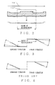
- Fig. 2 is a view cited for reference for explaining a process for producing the electrically conductive damper device for a speaker according to the present invention.
- the electrically conductive damper device consists of a main damper 141 and a reinforcing damper 142.
- the main damper 141 includes metallic wires incorporated therein by sewing, and thermosetting resin such as phenol resin or melamine resin which has been applied to or impregnated in the main damper before or after the metallic wires have been incorporated.
- the reinforcing damper 142 as well as the main damper 141, has thermosetting resin such as phenol resin or melamine resin applied to or impregnated therein, and is formed into an annular shape by stamping out its inner and outer peripheries.
- thermosetting resin such as phenol resin or melamine resin
- the damper member 14 can be obtained, by bonding the main damper 141 and the reinforcing damper 142 to each other, at the same time with shaping them. It is also possible that instead of applying the adhesive, a coating agent or a laminate film may be sandwiched between the main damper 141 and the reinforcing damper 142.
- a fabric or non woven fabric such as cotton, aramid fiber etc. may be employed as material of the main damper 141 and the reinforcing damper 142, to which the thermosetting resin as described above is applied or impregnated.
- Both ends of a braid of the metallic wires which are incorporated in the damper member 14 to compose the electrically conductive damper are connected respectively to the voice coil 13 and to an exterior input terminal. Audio signals inputted into the exterior terminal are applied to the voice coil 13 through the braid of the metallic wires, and the speaker apparatus as shown in Fig. 1 will be thus actuated.
- an area of the main damper 141 overlapped with the reinforcing damper 142 is defined as a range of reinforcement having double sheets.
- Fig. 3 is a view cited for reference for explaining movements of the electrically conductive damper device for a speaker according to the present invention, while vibrating (upward vibration and downward vibration) .
- Fig. 4 shows movements of the conventional damper device.
- the electrically conductive damper device for the speaker according to the present invention consists of the main damper 141, and another sheet of damper material attached to the neck portion of the main damper 141 for the purpose of reinforcement as the reinforcing damper 142.
- the two sheets of the damper material are bonded to each other with various kinds of resin.
- a local bending will be reduced, in other words, the bending at the neck portion will be dispersed. Because the outer peripheral area will be adequately bent on the other hand, the local bending will be moderated, and break-downs of the damper material and the metallic wires which have been incorporated will be prevented.
- an outer diameter of the reinforcing damper properties of the damper can be adjusted. More specifically, in case where the diameter of the reinforcing damper 142 is made larger, strength of the damper in its entirety will be increased. On the other hand, in case where the diameter of the reinforcing damper 142 is made smaller so as to be attached only to the area near the neck portion, the strength of the main damper 141 around the neck portion can be enhanced, while characteristics of the main damper 141 are maintained.
- the latter treatment may be an effective measure, because in modern speakers, the neck portion of the damper is the weakest point in strength and break-downs spreading from the neck portion are prominent. Moreover, in case where advantage should be taken of the characteristics of only the main damper 141, for example, in a speaker in which a special emphasis is placed on quality of sound, it is possible to restrict the range of reinforcement to a minimum around the neck portion.
- the resin to be employed here includes, for example, polyamide resin, urethane, acryl, NBR (acrylonitril-butadiene rubber), SBR (styrenebutadiene rubber) .
- polyamide resin urethane
- NBR acrylonitril-butadiene rubber
- SBR styrenebutadiene rubber
- the present invention can provide an electrically conductive damper device for a speaker in which a local bending is reduced and break-downs of the material of the damper and the metallic wires are prevented, by additionally providing one or more sheets of damper fabric as the reinforcing damper and by bonding it to the main damper by way of various kinds of resin, in order to reinforce the neck portion of the electrically conductive damper. Further, the properties of the damper can be adjusted by varying the outer diameter of the reinforcing damper, or by selecting the resin to be employed as the adhesive.
Landscapes
- Physics & Mathematics (AREA)
- Engineering & Computer Science (AREA)
- Acoustics & Sound (AREA)
- Signal Processing (AREA)
- Audible-Bandwidth Dynamoelectric Transducers Other Than Pickups (AREA)
Abstract
Description
Claims (7)
- An electrically conductive damper device for a speaker comprising a main damper which is formed of damper material having metallic wires attached thereto, and a reinforcing damper which is attached to a part of said main damper on which a voice coil bobbin is mounted.
- The electrically conductive damper device for the speaker as claimed in claim 1, wherein said damper material is formed of a fabric impregnated with thermosetting resin, and said metallic wires are formed of electrically conductive material, said main damper being formed by attaching said metallic wires to said fabric by sewing.
- The electrically conductive damper device for the speaker as claimed in claim 1, wherein said reinforcing damper is attached to such an area of said main damper that a local bending occurring at said mounting part of said voice coil bobbin when said voice coil bobbin is driven by a voice coil may be reduced, whereby said material of said main damper and said metallic wires may be prevented from breaking down.
- The electrically conductive damper device for the speaker as claimed in claim 1, wherein said main damper and said reinforcing damper are bonded to each other by means of an adhesive.
- The electrically conductive damper device for the speaker as claimed in claim 4, wherein said adhesive has an inner loss to such an extent that sympathetic vibrations of said electrically conductive damper occurring when said voice coil bobbin is driven may be dampened.
- The electrically conductive damper device for the speaker as claimed in claim 4, wherein said main damper and said reinforcing damper are bonded to each other by applying said adhesive.
- The electrically conductive damper device for the speaker as claimed in claim 4, wherein said main damper and said reinforcing damper are bonded to each other by sandwiching said adhesive between them and by fusion bonding.
Applications Claiming Priority (2)
| Application Number | Priority Date | Filing Date | Title |
|---|---|---|---|
| JP2001040195A JP2002247690A (en) | 2001-02-16 | 2001-02-16 | Conductive damper device for speaker |
| JP2001040195 | 2001-02-16 |
Publications (2)
| Publication Number | Publication Date |
|---|---|
| EP1233644A2 true EP1233644A2 (en) | 2002-08-21 |
| EP1233644A3 EP1233644A3 (en) | 2006-11-02 |
Family
ID=18902847
Family Applications (1)
| Application Number | Title | Priority Date | Filing Date |
|---|---|---|---|
| EP01125271A Withdrawn EP1233644A3 (en) | 2001-02-16 | 2001-10-24 | Electrically conductive damper device for speaker |
Country Status (3)
| Country | Link |
|---|---|
| US (1) | US6814181B2 (en) |
| EP (1) | EP1233644A3 (en) |
| JP (1) | JP2002247690A (en) |
Cited By (3)
| Publication number | Priority date | Publication date | Assignee | Title |
|---|---|---|---|---|
| WO2008106436A1 (en) * | 2007-02-28 | 2008-09-04 | Bose Corporation | Composite suspension system for electro-acoustic transducers |
| US7844071B2 (en) * | 2004-12-14 | 2010-11-30 | Panasonic Corporation | Loudspeaker |
| CN106162462A (en) * | 2016-08-18 | 2016-11-23 | 歌尔股份有限公司 | A kind of vibrational system in speech coil framework and speaker |
Families Citing this family (7)
| Publication number | Priority date | Publication date | Assignee | Title |
|---|---|---|---|---|
| USD522498S1 (en) * | 2004-08-17 | 2006-06-06 | Matsushita Electric Industrial Co., Ltd. | Speaker |
| JP2006129037A (en) * | 2004-10-28 | 2006-05-18 | Pioneer Electronic Corp | Speaker damper |
| JP2006325125A (en) * | 2005-05-20 | 2006-11-30 | Pioneer Electronic Corp | Diaphragm for speaker and manufacturing method thereof |
| US7899202B2 (en) * | 2006-04-17 | 2011-03-01 | Sound Sources Technology, Inc. | Loudspeaker with cone-coupled damper |
| US8855705B2 (en) | 2010-08-05 | 2014-10-07 | Blackberry Limited | Electronic device including actuator for providing tactile output |
| US8914075B2 (en) | 2010-09-17 | 2014-12-16 | Blackberry Limited | Electronic device including actuator and method of controlling same for providing tactile output |
| KR101697251B1 (en) * | 2011-01-04 | 2017-01-17 | 삼성전자주식회사 | speaker and method for assembling the speaker |
Family Cites Families (4)
| Publication number | Priority date | Publication date | Assignee | Title |
|---|---|---|---|---|
| US1480785A (en) * | 1922-05-24 | 1924-01-15 | Jr Charles E Semple | Diaphragm for sound reproducers |
| DE68920956T2 (en) * | 1988-11-15 | 1995-09-21 | Kenwood Corp | Loudspeaker damping arrangement. |
| KR970007296B1 (en) * | 1989-04-19 | 1997-05-07 | 가부시끼가이샤 켄우드 | Wiring structure of loudspeaker |
| JP3290107B2 (en) * | 1997-07-29 | 2002-06-10 | 株式会社ケンウッド | Conductive damper |
-
2001
- 2001-02-16 JP JP2001040195A patent/JP2002247690A/en active Pending
- 2001-10-22 US US09/982,750 patent/US6814181B2/en not_active Expired - Fee Related
- 2001-10-24 EP EP01125271A patent/EP1233644A3/en not_active Withdrawn
Cited By (5)
| Publication number | Priority date | Publication date | Assignee | Title |
|---|---|---|---|---|
| US7844071B2 (en) * | 2004-12-14 | 2010-11-30 | Panasonic Corporation | Loudspeaker |
| WO2008106436A1 (en) * | 2007-02-28 | 2008-09-04 | Bose Corporation | Composite suspension system for electro-acoustic transducers |
| US8315420B2 (en) | 2007-02-28 | 2012-11-20 | Bose Corporation | Spider |
| CN106162462A (en) * | 2016-08-18 | 2016-11-23 | 歌尔股份有限公司 | A kind of vibrational system in speech coil framework and speaker |
| CN106162462B (en) * | 2016-08-18 | 2019-09-17 | 歌尔股份有限公司 | A kind of vibrational system in speech coil framework and loudspeaker |
Also Published As
| Publication number | Publication date |
|---|---|
| EP1233644A3 (en) | 2006-11-02 |
| US6814181B2 (en) | 2004-11-09 |
| US20020112914A1 (en) | 2002-08-22 |
| JP2002247690A (en) | 2002-08-30 |
Similar Documents
| Publication | Publication Date | Title |
|---|---|---|
| EP1715720B1 (en) | Vibration system part for speaker device and manufacturing method thereof | |
| CN101960867B (en) | Speaker device | |
| US6814181B2 (en) | Electrically conductive damper device for speaker | |
| EP0769420A2 (en) | Speaker mount structure of vehicle | |
| US20120106772A1 (en) | Speaker device | |
| JP5037722B2 (en) | Vibration direction converter for speaker device and speaker device | |
| US7221773B2 (en) | Oval speaker apparatus and method of manufacturing the same | |
| JPWO2011004478A1 (en) | Speaker device | |
| WO2011004477A1 (en) | Speaker device | |
| US8059857B2 (en) | Voice coil bobbin and speaker system | |
| CN101489169A (en) | Speaker unit | |
| JP2005328336A (en) | Damper for loudspeaker device, loudspeaker device using its damper, and manufacturing method for loudspeaker device | |
| CN100399782C (en) | Electroacustic transducer | |
| EP1725074A1 (en) | Speaker diaphragm and method for manufacturing the same | |
| KR101667679B1 (en) | Vibration module for slim speaker and high-powered slim speaker including the vibration module | |
| US6772855B2 (en) | Damper for speaker and method of producing the same | |
| KR20200114297A (en) | Microspeaker having separated frame | |
| JP3094879U (en) | Multi-layer damper with conductor | |
| KR100313136B1 (en) | Microspeaker Having Center Cap and Damper Formed as One Bod y, and Method of Making the Same | |
| JP4013417B2 (en) | Speaker | |
| JPH10336788A (en) | Speaker damper and method of manufacturing the same | |
| JPH0698393A (en) | Speaker manufacturing method | |
| JP3131033B2 (en) | Speaker | |
| WO2011013222A1 (en) | Speaker device | |
| JP2006254159A (en) | Edge for speaker and speaker using the same |
Legal Events
| Date | Code | Title | Description |
|---|---|---|---|
| PUAI | Public reference made under article 153(3) epc to a published international application that has entered the european phase |
Free format text: ORIGINAL CODE: 0009012 |
|
| AK | Designated contracting states |
Kind code of ref document: A2 Designated state(s): AT BE CH CY DE DK ES FI FR GB GR IE IT LI LU MC NL PT SE TR |
|
| AX | Request for extension of the european patent |
Free format text: AL;LT;LV;MK;RO;SI |
|
| PUAL | Search report despatched |
Free format text: ORIGINAL CODE: 0009013 |
|
| AK | Designated contracting states |
Kind code of ref document: A3 Designated state(s): AT BE CH CY DE DK ES FI FR GB GR IE IT LI LU MC NL PT SE TR |
|
| AX | Request for extension of the european patent |
Extension state: AL LT LV MK RO SI |
|
| 17P | Request for examination filed |
Effective date: 20061123 |
|
| AKX | Designation fees paid |
Designated state(s): DE FR GB |
|
| 17Q | First examination report despatched |
Effective date: 20070831 |
|
| STAA | Information on the status of an ep patent application or granted ep patent |
Free format text: STATUS: THE APPLICATION IS DEEMED TO BE WITHDRAWN |
|
| 18D | Application deemed to be withdrawn |
Effective date: 20080111 |