EP1233611A2 - Image coding and decoding using intermediate images - Google Patents
Image coding and decoding using intermediate images Download PDFInfo
- Publication number
- EP1233611A2 EP1233611A2 EP02250977A EP02250977A EP1233611A2 EP 1233611 A2 EP1233611 A2 EP 1233611A2 EP 02250977 A EP02250977 A EP 02250977A EP 02250977 A EP02250977 A EP 02250977A EP 1233611 A2 EP1233611 A2 EP 1233611A2
- Authority
- EP
- European Patent Office
- Prior art keywords
- image
- intermediate image
- coding
- original
- original image
- Prior art date
- Legal status (The legal status is an assumption and is not a legal conclusion. Google has not performed a legal analysis and makes no representation as to the accuracy of the status listed.)
- Withdrawn
Links
Images


Classifications
-
- H—ELECTRICITY
- H04—ELECTRIC COMMUNICATION TECHNIQUE
- H04N—PICTORIAL COMMUNICATION, e.g. TELEVISION
- H04N19/00—Methods or arrangements for coding, decoding, compressing or decompressing digital video signals
- H04N19/10—Methods or arrangements for coding, decoding, compressing or decompressing digital video signals using adaptive coding
- H04N19/134—Methods or arrangements for coding, decoding, compressing or decompressing digital video signals using adaptive coding characterised by the element, parameter or criterion affecting or controlling the adaptive coding
- H04N19/162—User input
-
- H—ELECTRICITY
- H04—ELECTRIC COMMUNICATION TECHNIQUE
- H04N—PICTORIAL COMMUNICATION, e.g. TELEVISION
- H04N1/00—Scanning, transmission or reproduction of documents or the like, e.g. facsimile transmission; Details thereof
- H04N1/41—Bandwidth or redundancy reduction
-
- H—ELECTRICITY
- H04—ELECTRIC COMMUNICATION TECHNIQUE
- H04N—PICTORIAL COMMUNICATION, e.g. TELEVISION
- H04N19/00—Methods or arrangements for coding, decoding, compressing or decompressing digital video signals
- H04N19/60—Methods or arrangements for coding, decoding, compressing or decompressing digital video signals using transform coding
- H04N19/63—Methods or arrangements for coding, decoding, compressing or decompressing digital video signals using transform coding using sub-band based transform, e.g. wavelets
-
- H—ELECTRICITY
- H04—ELECTRIC COMMUNICATION TECHNIQUE
- H04N—PICTORIAL COMMUNICATION, e.g. TELEVISION
- H04N19/00—Methods or arrangements for coding, decoding, compressing or decompressing digital video signals
- H04N19/70—Methods or arrangements for coding, decoding, compressing or decompressing digital video signals characterised by syntax aspects related to video coding, e.g. related to compression standards
Definitions
- This invention relates to an image processing technique.
- This invention especially relates to an image processing method, and an image coding apparatus and an image decoding apparatus using the method.
- the standardization of the image data format has had the effect of facilitating data transmission and reception between digital devices. For instance, with a memory card of about half the size of a business card, data can be very easily exchanged between portable devices and information devices. The image data shot by a digital camera can be easily output to a color printer of fine quality that supports the same data format. It is expected that image data will be increasingly utilized in conjunction with various devices in the future.
- an image scaling is necessary.
- an image scaling is required.
- the scaling requires processing time and an amount of memory access, that is a bandwidth, in proportion to the size of the original image to be processed. Therefore, it creates a load in proportion to the 640 x 480 size of the original image to produce image data for an LCD output and thumbnail image data in this example.
- an image processing method comprises storing an intermediate image generated during a process of coding an original image and using or adopting the intermediate image as a new original image.
- the original image merely means an image provided when the coding starts.
- the intermediate image generated during the coding process is saved and reused. If the resolution of the intermediate image is lower than that of the original image and the resolution of the required coded image is low, it causes less processing load to code the intermediate image as a source image than to code the original image step by step. It is to be noted that the final image or image data obtained after the completion of the coding are only referred to as "a coded image” or “coded image data” and the expression does not imply the intermediate image.
- the intermediate image may be generated during a process of a hierarchical coding of the original image. This is advantageous because the intermediate image is often naturally generated during the hierarchizing process. Thereinafter the intermediate image implies an image in an intermediate layer.
- the intermediate image can be considered as a new original image and subjected to a desired process.
- the desired process may be image coding, scaling, enlarging or reducing the resolution or the size of an image, rotation, trimming, edge emphasis or high-pass filtering, smoothing, noise reduction or low-pass filtering, color translation, and other image processing.
- an image processing method more particularly an image decoding method.
- the method comprises storing an intermediate image, which is generated during a process of decoding coded image data generated through a coding of an original image, separately from a final decoded image, and substituting the intermediate image for the final decoded image in a manner appropriate to a predetermined use.
- the intermediate image is obtained and utilized. For instance, even if the intermediate image has a lower resolution than the final decoded image or the intermediate image has a low frequency component as a basic component, it is usable as far as it can be displayed. An image of such low resolution may be more convenient depending on the desired use of the image, and this embodiment is advantageous in such cases. It is to be noted that the final image obtained after the completion of the decoding is only referred to as "a decoded image" and this does not imply the intermediate image.
- a data structure retrievable and usable by a computer comprises a first data region which stores identification information of an original image, a second data region which stores an intermediate image generated during a process of coding the original image, and a header region which includes link information to connect the first and the second data regions.
- the header region may be included either in the first or the second data region.
- the coding of the original image may be a hierarchical coding
- the intermediate image may be an image which contains a low frequency component of the original image as a basic component.
- the intermediate image may be an image with a lower resolution than the original image.
- the two have high mutual substitutability.
- the coding of the original image may comprise a first processing step in which an image generated thereby remains intact to such an extent that the image can be displayed without a decoding process in such a manner that the original image is displayed, and a second processing step in which the image cannot be displayed without a decoding process in such a manner that the original image is displayed, and the intermediate image may be generated within the first processing step.
- an image coding apparatus comprises a coding unit which codes an original image, and an intermediate image memory which stores an intermediate image generated during the coding process separately from a final coded image.
- the coding unit may generate the intermediate image by hierarchizing the original image, or by reducing the resolution of the original image, or by utilizing low frequency components of the original image. Furthermore, the coding unit may generate the intermediate image using a sub-band which appears when a two-dimensional wavelet transform is conducted on the original image, and which is composed of low frequency components in both of x, y directions.
- the apparatus may further comprise an image selecting unit which selects either the original image or the intermediate image according to a particular use of the image, and forwards the selected image to the coding unit.
- an image selecting unit which selects either the original image or the intermediate image according to a particular use of the image, and forwards the selected image to the coding unit.
- a table which records the various uses in relation to appropriate the image sizes and other image attributes may be provided.
- an image coding apparatus comprises a shooting block, a block which controls the shooting block mechanically, and a processing block which processes a digital image obtained by the shooting block.
- the processing block comprises a coding unit which codes or encodes the digital image, and an intermediate image memory which stores an intermediate image generated during the coding process separately from a final coded image.
- the original image is not necessarily coded for each of a plurality of uses and it can contribute to a reduction in processing load and processing time in the apparatus.
- an image decoding apparatus comprises a decoding unit which decodes coded image data which are generated when an original image is coded, and an intermediate image memory which stores an intermediate image generated during the decoding process separately from a final decoded image.
- the intermediate image memory may store the intermediate image in association with the final decoded image.
- the apparatus may further comprise an image selecting unit which selects either the final decoded image or the intermediate image according to a particular use of the image and outputs the selected image.
- the intermediate image may have a lower resolution than the final decoded image.
- the intermediate image may include mainly a low frequency component of the final decoded image.
- the decoding unit may conduct a two-dimensional wavelet inverse transform during the decoding process and generate the intermediate image using a sub-band which is composed of low frequency components in x, y directions.
- an image decoding apparatus comprises a receiving block which receives a signal, a processing block which processes the received signal, and a play-back block which plays back the processed signal.
- the processing block comprises a decoding unit which decodes coded image data which comprises a digital image extracted from the received signal, and an intermediate image memory which stores an intermediate image generated during the decoding process separately from a final decoded image.
- the apparatus further comprises an interface block which outputs the intermediate image to an external device.
- the external device may be a passive element, for instance, a transmission medium such as a network or a memory.
- the intermediate image generated as a by-product or as temporary data during the process of obtaining the decoded image can be effectively utilized and thereby appropriate images can be obtained for different purposes during the sequence of the decoding process.
- an image processing method comprises storing an image, which is generated during a process of processing an original image for a predetermined purpose and remains intact to such an extent that an image can be displayed in the same manner as the original image, separately from the original image; and reusing the stored image in a manner appropriate to a particular use.
- an image processing method comprises extracting an image, which is generated during a process of restoring an image data and remains intact to such an extent that an image can be displayed in the same manner as an image to be finally obtained, separately from the image to be finally obtained.
- any arbitrary replacement or substitution of the above-described structural components and the steps, expressions replaced or substituted in part or whole between a method and an apparatus as well as addition thereof, and expressions changed to a system, a computer program, a data structure, recording medium or the like are all effective as and are encompassed by the present invention.
- JPEG 2000 is employed for image coding and decoding, however, the outline of JPEG 2000 is already known and therefore such known parts are not described hereinafter in detail.
- Fig. 1 shows the configuration of an image coding apparatus 10 according to Embodiment 1.
- the image coding apparatus 10 may be a normal computer and comprises a CPU, memory and program modules to code images loaded in the memory.
- the blocks in Fig. 1 depict functions characteristic of the present embodiment and those skilled in the art understand the functional blocks can be embodied as hardware only, software only or as a combination of the two.
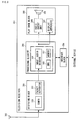
- the image coding apparatus 10 comprises a coding unit 12, an original image memory 26, an intermediate image memory 28, and an image selecting unit 38.
- the coding unit 12 which works on the specifications of JPEG 2000, comprises a wavelet transformer 14, a frame buffer 16, a quantizer 18, a bit-plane coder 20, an arithmetic coder 22 and a stream generator 24.
- An original image OI is read in the frame buffer 16 when the coding process starts. The image is input directly into the frame buffer 16 from the outside or input via the original image memory 26. In the following the image is assumed to be input via the original image memory 26.
- the original image OI in the frame buffer 16 is hierarchized by the wavelet transformer 14.
- the wavelet transformer 14 in JPEG 2000 employs a Daubechies filter. As shown in Fig. 2, the filter simultaneously works as a low-pass filter and a high-pass filter in x, y directions and divides the original image into four frequency sub-bands.
- the four sub-bands are: the LL sub-band which is composed of low frequency components in x and y directions, the HL and LH sub-bands which are composed of low frequency components in one of the x and y directions and high frequency components in the other direction, and the HH sub-band which is composed of high frequency components in x and y directions.
- the number of pixels in each sub-band image is half of those of the original image, respectively.
- the filtering process therefore renders four sub-band images, the sizes of which are one-fourth the size of the input image.
- the wavelet transformer 14 conducts a filtering process on the rendered LL sub-band, which is divided into LL, HL, LH and HH sub-bands.
- the LL sub-band rendered in the final filtering is obtained as an image which is closest to the DC component of the original image OI.
- High frequency components are dominant in the HH sub-band, followed by the HL and LH sub-bands, and the LL image in the same layer.
- the previous layer rendered in the previous filtering process comprises four sub-bands in which high frequency components are more dominant than those rendered in the present filtering process. In Fig. 2, for example, the upper left sub-band image has lower frequency components and the bottom right sub-band image has higher frequency components.
- the hierarchized image is input into the quantizer 18, the bit-plane coder 20, the arithmetic coder 22 and the stream generator 24 starting with the lowest frequency component, and the final coded image data CI are generated and output from the stream generator 24.
- the intermediate image memory 28 which is a structure characteristic of the present embodiment, stores an intermediate image II obtained during the process by the wavelet transformer 14. Normally, such an intermediate image II is generated temporarily in the frame buffer 16 and it has no special use by itself. However, the intermediate image is positively utilized in the present embodiment so that the advantages enumerated below can be obtained.
- the image selecting unit 38 includes an image memory controller 32, an image size determiner 34, and an image size table 36.
- the image may have various uses such as printing with a super fine quality and saving as a thumbnail image, and the quality and the resolution of the image may differ according to such various uses.
- the image size determiner 34 takes an input to determine the desired use of the image from the user.
- the image size table 36 records beforehand the various uses of the image and the resolution or the image size suitable for each of such uses.
- the image size determiner 34 determines a suitable image size by referring to the image size table 36 for the desired use input by the user.
- the memory controller 32 is notified of the result determined and provides the frame buffer 16 with the original image OI retrieved from the original image memory 26 or the intermediate image II of an appropriate size retrieved from the intermediate image memory 28, according to the suitability of the image size.
- Fig. 2 illustrates the relationship between the original image OI processed by the wavelet transformer 14 and the intermediate image II stored in the intermediate image memory 28.
- the original image OI is transformed into the first layer image WI1 during the first filtering by the wavelet transformer 14.
- the LL sub-band of this image WI1 is further filtered and the third layer image WI3 is finally generated in the case of Fig. 2.
- This image is thereafter processed by the quantizer 18 and the succeeding components.
- the intermediate memory 28 stores the LL sub-band image as an intermediate image, which is generated during the process by the wavelet transformer 14.
- the LL sub-band of the first layer image WI1 is stored immediately as an intermediate image II.
- the stored intermediate image II is reused according to the use specified by the user. For instance, when a quarter size of the original image OI is sufficient for the specified use, the intermediate image II recorded in the intermediate image memory 28 is retrieved and this image is provided to the frame buffer 16 as a new original image 40. Then the image is processed by the wavelet transformer 14 and the succeeding components and the coded image data 42 are generated.
- the advantages of using the intermediate image II are as follows.
- the new original image 40 retrieved from the intermediate image memory 28 is scaled down to an image 44 of the necessary size and the scaled image 44 is used as a source image for the coding so that the desired coded image data 46 can be obtained.
- the LL sub-band of the second layer image generated by the wavelet transform or the LL sub-band of the third layer image WI3 may be used as the intermediate image II. In any case, since an image whose size is smaller than that of the original image OI is used as a source image, the process is highly efficient.
- Fig. 3 illustrates a structure of the image data 50 stored in the intermediate image memory 28.
- the image data 50 includes the first data region 52 which stores an identifier ID (shown as "ID(OI)" in the figure) of the original image OI, and the second data region 54 which stores the data of the intermediate image II.
- the second data region 54 further includes a header region 56 (shown as "II header”) which records the header information relating to the intermediate image II, and a data region 58 (shown as "II data”) which stores the data relating to the intermediate image II itself.
- the header region 56 records a link to the first data region 52, which indicates that this intermediate image II is obtained by reference to the original image OI.
- Fig. 4 shows a detailed structure of the header region 56.
- the header region 56 includes the first sub-region 56a which stores the identifier ID (shown as "ID(II) in the figure) of the intermediate image II, the second sub-region 56b which stores the resolution information relevant to the intermediate image II, the third sub-region 56c which stores the image quality information concerning the intermediate image II, and the fourth sub-region 56 which stores the other information.
- the correspondence relation between the intermediate image II and the original image OI is identified by the content of the first sub-region 56a.
- the image memory controller 32 can extract an appropriate intermediate image II from the intermediate image memory 28 according to the content of the second sub-region 56b.
- the third sub-region 56c is an optional structure and it contains objective or subjective information regarding the image quality of the intermediate image II.
- the former information is, for example, an error in the intermediate image II with regard to the original image OI and the latter information is, for example, a judgment criterion regarding the suitability of the image for the specified use. For instance, if the intermediate image II is suitable for printing by a 300 dpi printer but cannot come up to the standard of a 1200 dpi printer, this fact is recorded in this region.
- the third sub-region 56c is also referred to by the image memory controller 32 and if one intermediate image II is not suitable for the use requested by the user, another intermediate image II or the original image OI is forwarded to the frame buffer 16.
- the fourth sub-region 56d is also an optional structure and it records, for instance, a process by which the intermediate image II is generated from the original image OI. This information will be referred to when appropriate, for instance when an intermediate image II is newly generated.
- Fig. 5 illustrates a detailed structure of the image size table 36.
- the image size table 36 contains a use column 70 and an image size column 72.
- the use column 70 the user's purpose for using the image such as a still image or a motion picture for a digital camera and so forth is listed.
- the image size column 72 the most appropriate image size appears, for instance, in a form such as 640 x 480.
- the uses described in the use column 70 are displayed to the user via the image size determiner 34 so that the user can select a desired use from among them.
- the image size described for each of the uses is defined on the basis of the specifications of the digital camera that the user possesses, the specifications of a generic digital camera, and so forth.
- the size of the original image OI is 640 x 480 and the recording of a still image for a digital camera is specified as a use by the user: in this case, since the image size suitable to the desired use is also 640 x 480 according to Fig. 5, the original image OI itself is forwarded to the coding unit 12 and the coded image data CI is generated.
- the intermediate image II is recorded in the intermediate image memory 28 during this coding process. For the purpose of explanation, let the intermediate image II of 320 x 240 size obtained through the first filtering by the wavelet transform 14 and the intermediate image II of 160 x 120 through the second filtering be recorded together in the intermediate image memory 28.
- the user might specify the recording of a motion picture for a digital camera.
- the appropriate size for the motion picture is 300 x 200 according to the image size column 72 of Fig. 5, and the intermediate image II of 320 x 240 size is retrieved from the intermediate image memory 28 and forwarded to the frame buffer 16. Thereafter, through the process of a CPU, a DSP and so forth not shown in the figure, the size of this intermediate image II is scaled down to 300 x 200 and processed by the wavelet transformer 14, the quantizer 18 and so forth and the coded image data CI of 300 x 200 size is finally output.
- To scale down from 320 x 240 to 300 x 200 requires only about one fourth of the load required if the original image OI is used as the source image for coding.
- the user might further indicate that an image shot by a digital camera should be saved as a thumbnail image for a digital album.
- An image size suitable for this use is determined to be 120 x 80 according to the image size column 72. Therefore the intermediate image II of 160 x 120 image size is retrieved from the intermediate image memory 28 by means of the link between the image size determiner 34 and the image memory controller 32 and it is forwarded to the frame buffer 16. Scaling is also conducted on this intermediate image II and its image size is scaled down to 120 x 80 and thereafter it is input into the wavelet transformer 14, the quantizer 18 and so forth, and finally coded image data CI are obtained. This scaling process requires only one-sixteenth of the processing required when the original image OI is used as the source image for coding.
- a suitable image size for this purpose is determined to be 320 x 240 according to the image size column 72.
- the intermediate image II of 320 x 240 image size is retrieved from the intermediate image memory 28 by means of the link between the image size determiner 34 and the image memory controller 32 and it is forwarded to the frame buffer 16. Since the size of this intermediate image II corresponds to the targeted image size, the scaling process can be skipped. Thereafter the image is input into the wavelet transformer 14, the quantizer 18 and so forth, and finally coded image data CI of the desired size are obtained.
- a digital camera can conduct the recording of a still image and the shooting of a movie picture simultaneously at high resolution.
- a still image and a thumbnail image are recorded simultaneously, a high-speed continuous shoot, for instance, can be easily conducted. Therefore, by exploiting the processes and the structures in JPEG 2000 and utilizing the high quality image filtering provided in JPEG 2000, an improvement in the efficiency of image processing can be achieved with a relatively simple configuration. Consequently, the commodity value of an image processing apparatus such as a digital camera or others can be enhanced and an improvement in its operability can be realized.
- Fig. 6 shows the configuration of an image decoding apparatus 100 according to Embodiment 2.
- the image decoding apparatus 100 can undertake the decoding procedure of JPEG 2000 and its main process can be said to be an inverse transform of the process in the image coding apparatus 10 of Fig. 1. It is to be noted that the structure similar to that of Fig. 1 has the same numeral mark assigned to it and its explanation is therefore omitted.
- the image decoding apparatus 100 includes a decoding unit 110, a decoded image memory 124, an intermediate image memory 28, and an image selecting unit 38.
- the coding unit 110 includes a stream analyzer 120 which sequentially processes coded image data CI, an arithmetic decoder 118, a bit-plane decoder 116, an inverse quantizer 114, a wavelet inverse transformer 112, and a frame buffer 16 which serves as a work area.
- the coded image data CI is processed by the stream analyzer 120 and the succeeding components and finally a decoded image DI is stored in the decoded image memory 124.
- the decoded image DI may be output directly.
- the case in which the decoded image DI is stored in the decoded image memory 124 is considered hereinafter.
- a process characteristic of the present embodiment is in that the intermediate image II generated during the process by the wavelet inverse transformer 112 is appropriately stored in the intermediate image memory 28.
- Fig. 7 shows the procedure followed by the image decoding apparatus 100.
- the provided coded image data CI is processed by the stream analyzer 120, the arithmetic coder 118, the bit-plane decoder 116, and the inverse quantizer 114 and thereby reverts to the third layer image WI3.
- the second layer image is obtained in the first inverse transform by the wavelet inverse transformer 112 and its LL sub-band 150 is recorded in the intermediate image memory 28.
- the image corresponding to the first layer is obtained in the second inverse transform by the wavelet inverse transformer 112 and its LL sub-band 152 is likewise recorded in the intermediate image memory 28.
- the decoded image DI is obtained in the third inverse transform and this image is stored in the decoded image memory 124.
- the small LL sub-band 150 obtained in the first inverse transform can be used as a thumbnail image for instance, while the LL sub-band 152 obtained in the second inverse transform can be output into an LCD and the largest decoded image DI finally obtained can be output into an external monitor or a printer.
- images of different sizes each of which is routinely decoded according to a particular use, can be obtained at a single decoding process. Therefore, as explained in reference to Embodiment 1, it is advantageous in reducing the processing load, and also allows the scaling process to be skipped.
- the present embodiment can also utilize the high quality image filtering facility of JPEG 2000 and thereby produce an excellent effect without necessitating an increase in the number of hardware components.
- the intermediate image II is already present to such an extent that it can be displayed in a manner similar to the manner in which the decoded image DI is displayed, already at the moment when the intermediate image II is extracted, and this fact is utilized. Namely the intermediate image II of a desired size can be effectively forwarded to various types of devices, each of which requires a different image size.
- Fig.8 shows the configuration of a digital camera 200 according to Embodiment 3.
- the digital camera 200 comprises a shooting block 202, a mechanism control block 204, a processing block 206, an LCD monitor 208 and operation buttons 210.
- the shooting block 202 comprises a lens, a lens stop, an optical low-pass filter (LPF), a CCD and a signal processor (not shown).
- the CCD accumulates charge according to the amount of light received from an object imaged on the light receiving plane of the CCD.
- the charge is read as a voltage signal, which is decomposed into R, G and B components in the signal processor.
- the components are subjected to white balance adjustment and gamma correction.
- the R, G and B signals are then input into an A/D converter from which digital image data are output to the processing block 206.
- the mechanism control block 204 controls the optical system including zooming, focusing and iris of the shooting block 202.
- the processing block 206 comprises a CPU 220, memory 222, a YC processor 226, a card controller 228 and a communication unit 224.
- the image coding apparatus 10 of Embodiment 1 is realized with some of the functions of the CPU 220, and an image coding program loaded in the memory 222.
- the frame buffer 16, the original image memory 26, and the intermediate image memory 28 of Embodiment 1 are realized using part of the memory 222.
- the YC processor 226 From the digital image data the YC processor 226 generates a luminance signal Y, chroma signals B-Y and R-Y. The luminance signal and the chroma signals are separately coded in the original image OI.
- the coded image data CI are output via the communication unit 224 or are written into the memory card 230 via the card controller 228.
- the communication unit 224 conducts a protocol transform in accordance with a standardized communication specification.
- the communication unit 224 may transmit data from and to a printer, a game player and other external devices via respective interfaces.
- the LCD monitor 208 displays the image of an object, shooting/replay mode, zoom ratio, date, and so on.
- the operation buttons 210 may include a power switch, a release switch and so on to shoot a picture or to set operational modes.
- Fig. 9 shows the configuration of a television receiver 300.
- the television receiver 300 includes an antenna 302, a receiving block 304 which receives a broadcast wave via the antenna 302, a processing block 306 which processes image and audio data obtained through the process applied by the receiving block 304, and a play-back block 308 which plays the audio and image data decoded by the processing block 306.
- An interface block 336 outputs the image data decoded by the processing block 306 to an appropriate external device.
- the receiving block 304 includes a tuner 320 and a packet separator 322.
- the tuner 320 selects a transponder which includes a channel selected by a user and conducts a QPSK demodulation.
- a stream which includes a plurality of transport packets obtained in the demodulation is forwarded to the packet separator 322.
- the packet separator 322 is a demultiplexer and it separates a packet corresponding to a desired channel and outputs to the processing block 306.
- An image and audio decoder 334 in the processing block 306 works in cooperation with a CPU 330 and a memory 332 and thereby decodes the image and audio data which are coded and transmitted by a broadcasting station.
- the image and audio decoder 334 decodes an input packet and outputs audio data to an audio output unit 340 and image data to a display apparatus 344.
- the audio output unit 340 conducts a predetermined process on the input audio data and finally audio is output to a speaker 342.
- the part of the configuration of the processing block 306, that is the image and audio decoder 334, the CPU 330, and the memory 332, which relates to the image decoding, corresponds to the image decoding apparatus 100 of Embodiment 2.
- image coding and decoding are explained as an example of image processing, however, the present invention is not only limited to these, but also applicable to any image processing in which any transitive status in the image process can be recorded as an intermediate image.
- the filter may be any filter such as a normal average filter and the like.
- the present invention can be advantageously applied to image processing of any progressive nature. For instance, if an image that appears at an earlier stage of the progressive display is saved as an intermediate image, it can be reused for a predetermined purpose.
- the scaling in the embodiments is a process in a reducing direction, however, as a matter of course this may be a process in the direction of extension. In such a case, an interpolation process may be applied between pixels so that the image size can be scaled up.
- Fig. 1 and Fig. 6 depict the intermediate image memory 28 as an independent structure, however, this memory may be unified with other memories such as the frame buffer 16 and others. In essence, it is sufficient that there exists a memory area for saving the intermediate image II.
- Embodiment 1 the image coding apparatus 10 is explained as a unified configuration
- Embodiment 2 the image decoding apparatus 100 is explained as a unified configuration. Any parts of these configurations, however, may exist in remote locations and the configurations as a whole may have a function of utilizing an intermediate image.
- the original image memory 26 and the intermediate image memory 28 of Fig. 1, the decoded image memory 124 of Fig. 6 and so forth may be stored in a remote storage facility such as a hard disc and thereby a digital archive with a high potential for reusability can be built up for future use.
- the image data 50 of Fig. 3 relate the intermediate image data with the original image.
- the coded image data CI may be stored related with these data. In this case, the most appropriate data can be used according to various uses and situations.
- the image selecting unit 38 of Fig. 1 and Fig. 6 is an optional structure and it may receive an instruction concerning an image selection directly from the outside and may appropriately retrieve an intermediate image using the instruction.
- a digital camera is included in the explanation of Embodiment 3.
- the present invention may naturally be applied to other electronic devices.
- the present invention can be easily applied to a facsimile machine, a copy machine, a scanner and the like which have a shooting block and a processing block.
- a television receiver is included in the explanation of Embodiment 4.
- the present invention may be applied to other items of apparatus which have a receiving block and a processing block such as a mobile phone accessible to the Internet or various types of PDA (Personal Digital Assistant).
- PDA Personal Digital Assistant
Landscapes
- Engineering & Computer Science (AREA)
- Multimedia (AREA)
- Signal Processing (AREA)
- Compression Or Coding Systems Of Tv Signals (AREA)
- Compression Of Band Width Or Redundancy In Fax (AREA)
- Editing Of Facsimile Originals (AREA)
- Compression, Expansion, Code Conversion, And Decoders (AREA)
- Television Signal Processing For Recording (AREA)
Abstract
Description
Claims (15)
- An image coding method comprising storing an intermediate image generated during a process of coding an original image and using the intermediate image as a new original image.
- An image decoding method comprising storing an intermediate image, which is generated during a process of decoding coded image data generated through a coding of an original image, separately from a final decoded image, and substituting the intermediate image for the final decoded image according to a specified use.
- The method of any one of Claims 1-2, wherein the intermediate image is an image with a lower resolution than the original image and a scaling process is skipped automatically by using the intermediate image.
- A data structure retrievable and usable by a computer, the data structure comprising:a first data region (52) which stores identification information of an original image;a second data region (54) which stores an intermediate image generated during a process of coding the original image; anda header region (56) which includes link information to connect the first and the second data regions.
- An image coding apparatus comprising:a coding unit (12) which codes an original image; andan intermediate image memory (28) which stores an intermediate image generated during the coding process separately from a final coded image.
- The apparatus of Claim 5, wherein the coding unit (12) retrieves the intermediate image if necessary and codes the intermediate image as a new original image.
- The apparatus of any one of Claims 5-6, wherein the coding unit (12) generates the intermediate image by hierarchizing the original image.
- The apparatus of Claim 7, wherein the coding unit (12) generates the intermediate image using a sub-band which appears when a two-dimensional wavelet transform is conducted on the original image, and which is composed of low frequency components in x, y directions.
- The apparatus of any one of Claims 5-8, wherein the intermediate image memory (28) stores the intermediate image in relation with the original image.
- The apparatus of any one of Claims 5-9, further comprising an image selecting unit (38) which selects either the original image or the intermediate image according to a specified use of the image, and forwards the selected image to the coding unit (12).
- An image decoding apparatus comprising:a decoding unit (110) which decodes coded image data which are generated when an original image is coded; andan intermediate image memory (28) which stores an intermediate image generated during the decoding process separately from a final decoded image.
- The apparatus of Claim 11, wherein the decoding unit (110) conducts the decoding process on an assumption that the original image is coded hierarchically and generates the intermediate image.
- The apparatus of any one of Claims 11-12, wherein the decoding unit (110) conducts a two-dimensional wavelet inverse transform during the decoding process and generates the intermediate image using a sub-band which is composed of low frequency components in x, y directions.
- The apparatus of any one of Claims 11-13, wherein the intermediate image memory (28) stores the intermediate image in relation with the final decoded image.
- The apparatus of any one of Claims 11-14, further comprising an image selecting unit (38) which selects either the final decoded image or the intermediate image according to a specified use of the image and outputs the selected image.
Applications Claiming Priority (2)
| Application Number | Priority Date | Filing Date | Title |
|---|---|---|---|
| JP2001044004A JP4067281B2 (en) | 2001-02-20 | 2001-02-20 | Image processing method and image encoding apparatus and image decoding apparatus capable of using the method |
| JP2001044004 | 2001-02-20 |
Publications (2)
| Publication Number | Publication Date |
|---|---|
| EP1233611A2 true EP1233611A2 (en) | 2002-08-21 |
| EP1233611A3 EP1233611A3 (en) | 2005-08-31 |
Family
ID=18906072
Family Applications (1)
| Application Number | Title | Priority Date | Filing Date |
|---|---|---|---|
| EP20020250977 Withdrawn EP1233611A3 (en) | 2001-02-20 | 2002-02-13 | Image coding and decoding using intermediate images |
Country Status (5)
| Country | Link |
|---|---|
| US (1) | US7333662B2 (en) |
| EP (1) | EP1233611A3 (en) |
| JP (1) | JP4067281B2 (en) |
| KR (1) | KR100630983B1 (en) |
| TW (1) | TW548978B (en) |
Families Citing this family (22)
| Publication number | Priority date | Publication date | Assignee | Title |
|---|---|---|---|---|
| JP2002359846A (en) * | 2001-05-31 | 2002-12-13 | Sanyo Electric Co Ltd | Image decoding method and apparatus |
| JP2003283839A (en) * | 2002-03-19 | 2003-10-03 | Sanyo Electric Co Ltd | Image conversion method and apparatus |
| US7454069B2 (en) | 2002-11-20 | 2008-11-18 | Ricoh Company, Ltd. | Image processing apparatus, image compressing apparatus, image decompressing apparatus, image processing method, image compressing method, image decompressing method, information processing apparatus, information processing method, program and recording medium |
| JP4406816B2 (en) * | 2002-12-11 | 2010-02-03 | ソニー株式会社 | Receiving apparatus and receiving method, recording medium, and program |
| JP2004236299A (en) * | 2003-01-07 | 2004-08-19 | Ricoh Co Ltd | Image processing apparatus, image forming apparatus, image processing method, program, and storage medium |
| JP4349816B2 (en) | 2003-02-17 | 2009-10-21 | 株式会社リコー | Image processing apparatus, image compression apparatus, image processing method, image compression method, program, and recording medium |
| JP2004248152A (en) | 2003-02-17 | 2004-09-02 | Ricoh Co Ltd | Image compression device, image decompression device, image compression method, image decompression method, program, and recording medium |
| JP3791505B2 (en) | 2003-03-14 | 2006-06-28 | コニカミノルタビジネステクノロジーズ株式会社 | Image processing device |
| US20040223066A1 (en) * | 2003-05-07 | 2004-11-11 | Eastman Kodak Company | Camera having header data indicative of a camera funciton embedded with actual image data for synchronizing the camera function and image data |
| JP2005031389A (en) * | 2003-07-14 | 2005-02-03 | Ricoh Co Ltd | Image processing apparatus, image display system, program, and storage medium |
| FI20031816A0 (en) * | 2003-12-11 | 2003-12-11 | Nokia Corp | Method and device for creating an image |
| WO2005094066A1 (en) * | 2004-03-25 | 2005-10-06 | Sony Corporation | Information signal processing device, function block control method, and function block |
| EP1729500A4 (en) | 2004-10-06 | 2007-10-03 | Nippon Telegraph & Telephone | METHOD AND DEVICE FOR MODULAR ENCODING, METHOD AND DEVICE FOR MODULAR DECODING, PROGRAMS FOR THEM, AND RECORDING MEDIUM ON WHICH PROGRAMS ARE RECORDED |
| KR100735918B1 (en) * | 2004-12-22 | 2007-07-06 | 삼성전자주식회사 | Display device and image processing method thereof |
| JP4618676B2 (en) | 2005-04-28 | 2011-01-26 | 株式会社リコー | Structured document code transfer method, image processing system, server device, program, and information recording medium |
| KR101290275B1 (en) * | 2007-01-16 | 2013-08-07 | 삼성전자주식회사 | Apparatus and method for transporting and receiving graphic data |
| US20090022412A1 (en) * | 2007-07-20 | 2009-01-22 | Sanyo Electric Co., Ltd. | Image processing apparatus and image pickup apparatus using the same |
| JP5203824B2 (en) * | 2008-07-10 | 2013-06-05 | オリンパス株式会社 | Image processing apparatus and imaging system |
| JP2011118619A (en) * | 2009-12-02 | 2011-06-16 | Seiko Epson Corp | File management device |
| US20120275502A1 (en) * | 2011-04-26 | 2012-11-01 | Fang-Yi Hsieh | Apparatus for dynamically adjusting video decoding complexity, and associated method |
| JP5832280B2 (en) * | 2011-12-27 | 2015-12-16 | キヤノン株式会社 | Display control apparatus, control method therefor, program, and storage medium |
| US9025900B1 (en) * | 2012-09-07 | 2015-05-05 | Trend Micro Inc. | Distributed image storage using cloud |
Family Cites Families (15)
| Publication number | Priority date | Publication date | Assignee | Title |
|---|---|---|---|---|
| GB8630887D0 (en) * | 1986-12-24 | 1987-02-04 | Philips Electronic Associated | Encoding & displaying pictures |
| JP3162773B2 (en) * | 1992-01-06 | 2001-05-08 | キヤノン株式会社 | Image processing method and apparatus |
| JP3428678B2 (en) * | 1993-04-21 | 2003-07-22 | キヤノン株式会社 | Image processing apparatus and method |
| JP3373008B2 (en) | 1993-10-20 | 2003-02-04 | オリンパス光学工業株式会社 | Image area separation device |
| KR960028543A (en) * | 1994-12-28 | 1996-07-22 | 배순훈 | Video Coding Device Using Wavelet Transform |
| EP0763943A3 (en) * | 1995-09-12 | 1999-07-14 | Matsushita Electric Industrial Co., Ltd. | Coding method and wavelet transform apparatus |
| KR100211840B1 (en) * | 1997-01-15 | 1999-08-02 | 윤종용 | How to create a thumbnail image on a digital still camera |
| KR100254489B1 (en) * | 1997-04-30 | 2000-06-01 | 구자홍 | Variable frame rate and image quality of playback device |
| KR19990050598A (en) | 1997-12-17 | 1999-07-05 | 전주범 | Sub-screen Image Processing Apparatus by Wavelet Transformation of Multi-Screen Television |
| KR100252810B1 (en) * | 1997-12-30 | 2000-04-15 | 김영환 | MPEG Decoder |
| US6041143A (en) * | 1998-04-14 | 2000-03-21 | Teralogic Incorporated | Multiresolution compressed image management system and method |
| JP3613983B2 (en) | 1998-06-25 | 2005-01-26 | ソニー株式会社 | Image generating apparatus and method, and electronic still camera |
| JP4256500B2 (en) | 1998-10-20 | 2009-04-22 | 総夫 山田 | Remote image monitoring device with index image search function |
| FR2792432B1 (en) * | 1999-04-15 | 2001-07-13 | Canon Kk | DEVICE AND METHOD FOR DIGITAL SIGNAL TRANSFORMATION |
| JP2002359846A (en) * | 2001-05-31 | 2002-12-13 | Sanyo Electric Co Ltd | Image decoding method and apparatus |
-
2001
- 2001-02-20 JP JP2001044004A patent/JP4067281B2/en not_active Expired - Fee Related
-
2002
- 2002-01-14 TW TW91100360A patent/TW548978B/en not_active IP Right Cessation
- 2002-02-13 EP EP20020250977 patent/EP1233611A3/en not_active Withdrawn
- 2002-02-14 US US10/077,209 patent/US7333662B2/en not_active Expired - Fee Related
- 2002-02-18 KR KR20020008420A patent/KR100630983B1/en not_active Expired - Fee Related
Also Published As
| Publication number | Publication date |
|---|---|
| EP1233611A3 (en) | 2005-08-31 |
| TW548978B (en) | 2003-08-21 |
| KR100630983B1 (en) | 2006-10-09 |
| US20020154826A1 (en) | 2002-10-24 |
| US7333662B2 (en) | 2008-02-19 |
| JP4067281B2 (en) | 2008-03-26 |
| JP2002247580A (en) | 2002-08-30 |
| KR20020068272A (en) | 2002-08-27 |
Similar Documents
| Publication | Publication Date | Title |
|---|---|---|
| US7333662B2 (en) | Image coding and decoding using intermediate images | |
| KR100512210B1 (en) | Method and apparatus for decoding image | |
| US20040212843A1 (en) | Image processing method, image processing apparatus, electronic camera and computer-readable storage medium | |
| US20060045381A1 (en) | Image processing apparatus, shooting apparatus and image display apparatus | |
| US20090290645A1 (en) | System and Method for Using Coded Data From a Video Source to Compress a Media Signal | |
| JPH11331847A (en) | Image conversion method, digital camera and computer system | |
| JP2002135783A (en) | Variable bit rate processing method for streaming service | |
| US7889936B2 (en) | Image forming apparatus and image forming method | |
| US7643700B2 (en) | Processing of coded data according to user preference | |
| Perra | Re-encoding JPEG images for smart phone applications | |
| JP4154178B2 (en) | Video camera | |
| JP4073333B2 (en) | Image compression apparatus and image compression method | |
| JP2002077844A (en) | Image transmission apparatus, image transmission method, and computer-readable recording medium recording image transmission program | |
| JP4129913B2 (en) | Image processing apparatus and image processing method | |
| US20050105811A1 (en) | Processing images | |
| JP2003339003A (en) | Image photographing delivery device and image photographing delivery method | |
| JP2005051810A (en) | Digital camera | |
| JP3825871B2 (en) | Image processing apparatus and method, and computer-readable recording medium storing image processing program code | |
| JP3877742B2 (en) | Digital camera | |
| JP4338727B2 (en) | Image processing device | |
| JP4338725B2 (en) | Image processing device | |
| JP4338726B2 (en) | Image processing device | |
| JP2001346158A (en) | Memory control device, digital camera and image processing device | |
| JP2004140879A (en) | Digital camera and image processing method in digital camera | |
| US20060056718A1 (en) | Method, device and computer program for encoding digital image |
Legal Events
| Date | Code | Title | Description |
|---|---|---|---|
| PUAI | Public reference made under article 153(3) epc to a published international application that has entered the european phase |
Free format text: ORIGINAL CODE: 0009012 |
|
| AK | Designated contracting states |
Kind code of ref document: A2 Designated state(s): AT BE CH CY DE DK ES FI FR GB GR IE IT LI LU MC NL PT SE TR |
|
| AX | Request for extension of the european patent |
Free format text: AL;LT;LV;MK;RO;SI |
|
| PUAL | Search report despatched |
Free format text: ORIGINAL CODE: 0009013 |
|
| AK | Designated contracting states |
Kind code of ref document: A3 Designated state(s): AT BE CH CY DE DK ES FI FR GB GR IE IT LI LU MC NL PT SE TR |
|
| AX | Request for extension of the european patent |
Extension state: AL LT LV MK RO SI |
|
| 17P | Request for examination filed |
Effective date: 20060214 |
|
| AKX | Designation fees paid |
Designated state(s): DE FR GB |
|
| STAA | Information on the status of an ep patent application or granted ep patent |
Free format text: STATUS: THE APPLICATION HAS BEEN WITHDRAWN |
|
| 18W | Application withdrawn |
Effective date: 20070212 |