EP1233507A1 - Digital transmitter system and method - Google Patents
Digital transmitter system and method Download PDFInfo
- Publication number
- EP1233507A1 EP1233507A1 EP02250556A EP02250556A EP1233507A1 EP 1233507 A1 EP1233507 A1 EP 1233507A1 EP 02250556 A EP02250556 A EP 02250556A EP 02250556 A EP02250556 A EP 02250556A EP 1233507 A1 EP1233507 A1 EP 1233507A1
- Authority
- EP
- European Patent Office
- Prior art keywords
- analog signal
- analog
- digital
- frequency
- image
- Prior art date
- Legal status (The legal status is an assumption and is not a legal conclusion. Google has not performed a legal analysis and makes no representation as to the accuracy of the status listed.)
- Granted
Links
Images


Classifications
-
- H—ELECTRICITY
- H04—ELECTRIC COMMUNICATION TECHNIQUE
- H04B—TRANSMISSION
- H04B1/00—Details of transmission systems, not covered by a single one of groups H04B3/00 - H04B13/00; Details of transmission systems not characterised by the medium used for transmission
- H04B1/02—Transmitters
-
- H—ELECTRICITY
- H03—ELECTRONIC CIRCUITRY
- H03C—MODULATION
- H03C1/00—Amplitude modulation
-
- H—ELECTRICITY
- H04—ELECTRIC COMMUNICATION TECHNIQUE
- H04B—TRANSMISSION
- H04B1/00—Details of transmission systems, not covered by a single one of groups H04B3/00 - H04B13/00; Details of transmission systems not characterised by the medium used for transmission
- H04B1/02—Transmitters
- H04B1/04—Circuits
Definitions
- This invention relates to wireless communications and, more particularly, to a digital transmitter architecture for a wireless communications system.
- the service area of a wireless communications system is partitioned into connected service domains known as cells, where wireless units communicate via radio links with a base station (BS) serving the cell.
- the base station is coupled to a land network, for example through a Mobile Switching Center (MSC) which is connected to a plurality of base stations dispersed throughout the service area.
- MSC Mobile Switching Center
- service providers are often granted two or more non-contiguous or segregated frequency bands to be used for the wireless transmission and reception of RF communications channels.
- a base station for an "A" band provider for cellular communications receives frequency channels within the A (825-835 MHz), A' (845-846.5 MHz) and A" (824-825MHz) bands, and transmit on frequency channels within the A (870-880 MHz), A' (890-891.5 MHz) and A" (869-870MHz) bands.
- a base station for a B band provider receives frequency channels within the B (835-845MHz) and B'(846.5-849 MHz) frequency bands, and transmits on frequency channels within the B (880-890MHz) and B'(891.5-894 MHz) frequency bands.
- a base station for a Personal Communications Systems (PCS) provider may receive frequency channels from wireless units on one or more blocks of the PCS band (1850MHz-1910MHz), and transmit on frequency channels on one or more blocks of the PCS band (1930-1990 MHz).
- PCS Personal Communications Systems
- the baseband information signals are digital signals which are provided to signal processing units (SPUs).
- SPUs take the baseband digital signals and perform encoding, error detection processing, bit interleaving and digital in-phase (I) and quadrature (Q) modulation on the digital signals.
- the resulting digital (I/Q) modulated intermediate frequency (IF) signals are summed together and provided to a digital to analog converter (DAC).
- the DAC converts the digital IF signals into analog IF signals which are frequency upconverted using analog mixers into analog radio frequency (RF) signals for transmission at the appropriate frequency bands.
- RF radio frequency
- the transmission systems have an analog low pass filter to remove periodic images of the analog IF signals produced at higher frequencies by the DAC as a result of the digital to analog conversion process.
- the digital IF spectrum is converted into the analog domain by a DAC at a conversion rate
- the signal bandwidth rotates, or folds, periodically at multiples of one-half the conversion frequency.
- replica and mirror images of the signal bandwidth are periodically repeated at frequency intervals corresponding to the conversion rate of the DAC.
- the DAC converts the 10 MHz digital signal to a fundamental analog signal image 12a at 10MHz. With a conversion rate of 30 MHz, the DAC outputs a mirror image 14a at 20 MHz of the fundamental analog signal 12a.
- a replica image 12b of the analog signal is produced at 40 MHz, and a mirror image 14b is produced at 50 MHz along with a replica image 12c at 70 MHz and a mirror image 14c at 80 MHz.
- LPF analog low pass filter
- the DAC With a conversion rate of 60 MHz (or 60 Msps or 60 Mwps), the DAC outputs the fundamental 10 MHz analog signal image 16a along with a mirror image 18a at 50 MHz. Because the signal bandwidth and mirror images of the signal bandwidth are periodically repeated at frequency intervals corresponding to the conversion rate, a replica image 16b of the analog signal is produced at 70 MHz, and a mirror image 18b is produced at 110 MHz. As described above, current design practices use an analog low pass filter (LPF) to remove any images 16b, 18a, 18b and so on from the output of the DAC, leaving the fundamental 10MHz analog signal image for upconversion to the appropriate RF frequency for transmission.
- LPF analog low pass filter
- the present invention is a digital transmitter which converts a digital signal into analog form with a digital to analog converter (DAC) and uses an analog signal image produced from the DAC to provide an analog signal at a transmission frequency and/or uses a projected analog signal image to produce analog signals for transmission.
- the digital transmitter uses the analog signal images from the DAC to produce the analog signals at the desired frequency/frequencies.
- the analog signal images produced from the DAC can be positioned in the desired frequency band(s).
- the digital transmitter can position the digital signals within non-overlapping portions of a conversion bandwidth defined as one-half the conversion rate for the DAC.
- the DAC produces analog signal images periodically repeated at multiples of one-half the conversion rate such that analog signal images are produced at the appropriate frequency band(s) for amplification and transmission.
- FIG. 2a shows a digital transmitter 20 including a DAC 22 which receives at least one digital signal.
- the DAC 22 converts the digital signal spectrum at a conversion rate f c .
- the conversion rate f c for the DAC is chosen such that the conversion bandwidth from 0 Hz to one-half of the conversion rate encompasses the bandwidth of the digital signal(s). The higher the conversion rate, the wider is the conversion bandwidth. If the digital signal bandwidth is greater than one-half the conversion rate, an undesirable overlapping between the projected images can occur.
- the DAC converts the digital signals (F1-FN) using a conversion rate f c encompassing the digital signals from frequencies F1 to FN within a conversion bandwidth equal to one-half the conversion rate.
- the conversion bandwidth or fundamental analog image 24 rotates or folds periodically at multiples of one-half the conversion frequency f c to produce a mirrored first projected analog image 26a, a replica second projected analog image 26b and a mirrored third projected analog image 26c of the fundamental image 24 containing the analog signals (F1-FN).
- Analog image can refer to the fundamental analog image produced from 0 Hz to one-half the conversion rate by converting the digital spectrum into analog form at the conversion rate as well as any projected replica or mirrored analog images of the fundamental analog image.
- Analog signal image can refer to a fundamental analog signal image as well as the corresponding projected analog signal images of the fundamental analog signal image resulting from converting a particular digital signal(s) within the digital signal spectrum into analog form.
- the converted digital signals can be positioned at frequencies such that when the digital signals are converted into analog form, the analog signal images fall at the desired frequencies. If the fundamental analog signal image is at the desired transmission frequency, the fundamental analog signal image can be directly amplified and transmitted at the desired transmission frequency without frequency conversion in the analog domain. If the fundamental analog signal image is not at the desired transmission frequency, the digital transmitter can use the subsequent analog signal images which are projected from the fundamental analog signal image to produce the desired analog signal for transmission. As such, rather than filtering the analog signal images from the fundamental analog signal image, a projected analog signal image which falls on a desired transmission frequency can be directly amplified and transmitted.
- the projected analog signal image could also fall on a desired intermediate frequency (IF) which can be frequency converted to an intermediate or eventually a transmission frequency for amplification and transmission.
- IF intermediate frequency
- Projected analog signal images refers to a replica or mirror image of the fundamental analog signal image.
- the digital transmitter does not need to filter out the analog images nor rely only on frequency conversion in the analog domain to position the analog signals in the appropriate transmission band(s).
- the digital transmitter provides flexibility and efficient use of the available conversion bandwidth established by the conversion rate. For example, if the digital signals that are converted into analog form are to be transmitted in non-contiguous frequency bands, the conversion bandwidth could encompass the non-contiguous bands if a high enough conversion rate is available. If not or if desired, the digital transmitter can position the digital signals within the conversion bandwidth at positions independent of the relative positioning between the corresponding analog signals at the transmission frequencies. For example, the digital signals can be positioned closer together in the conversion bandwidth than the corresponding analog signals at their transmission frequencies. After the digital transmitter converts the digital signals into analog form, analog signal images in different zones (or different multiples of one-half the conversion rate) can be used to produce analog signals in the non-contiguous transmission bands.
- a digital transmitter may be able to communicate on a plurality of wireless communications frequencies, such as PCS or cellular, and/or using a plurality of wireless communications protocols, such as CDMA, GSM, North American TDMA or others.
- a wireless communications frequency(ies) and/or wireless communication protocol(s) to be used by the digital transmitter base station or wireless unit
- the conversion rate to be used can be set and/or the position of the digital signal(s) adjusted such that the resulting analog signal image falls on the desired transmission frequency(ies).
- the wireless unit may not have information on the type of wireless communication frequency/frequencies and/or protocol(s) used in the system, or the system could use a plurality of non-contiguous frequency band and/or protocols.
- the wireless unit could set the digital signal frequencies and/or conversion rate to transmit analog signals simultaneously using different frequency bands and/or protocols.
- the wireless unit could transmit using one frequency band/protocol combination at a time for analog signal transmissions, for example by changing the conversion rate and/or digital signal frequency(ies) for each analog signal transmissions corresponding to at least each different frequency band.
- the digital signal frequency(ies) and/or conversion rates for the desired type of analog signal transmission could be, predetermined and set for a single frequency band/protocol configuration, predetermined and stored for a plurality of frequency/protocol configurations and/or determined or calculated in the wireless unit or base station or received from the wireless unit or the wireless communications system depending on the embodiment.
- Configuration settings could also include amplifier bias and/or predistortion settings.
- a coupling network or signal distribution network 30, such as a power divider or a N-plexer, receives the entire analog signal spectrum from the DAC 22 and combines and/or separates the analog signals or portions thereof and provides the analog signals onto transmission, amplification or channel branches or paths 31a-x in a desired manner.
- the paths 31a-x can carry the analog signals for corresponding RF frequency bands, can carry analog signals to be transmitted on different antenna(s) or sets of antennas, and/or can have copies of the analog signals of different or contiguous frequency bands.
- the coupling network 30 can simply include direct connection(s) from the DAC 22 to each filter 32a-x, and each filter 32a-x is connected to a corresponding antenna 36a-x. If the transmitter 20 has a single transmission branch 31, the coupling network 30 includes a connection from the DAC 22 through a filter 32, an amplifier 34 to an antenna 36.
- the numbers of paths 31a-x, filters 32a-x, amplifiers 34a-x and antennas 36a-x can be equal to or greater than one and can be different and/or equal to each other.
- the coupling network 30 provides the desired analog signals f1 to fN to paths 31a-x for amplification and transmission.
- bandpass filters 32a-32x of the coupling network 30 allow the analog signals at the desired frequencies fl to fN to pass on the corresponding path 31a-x while attenuating all other signal frequencies.
- the desired analog signals f1 to fN are amplified by amplifiers 34a-x and transmitted by antennas 36a-x. As shown in FIG. 2b, the desired frequencies f1-fN for the analog signals are at different portions of the analog signal spectrum.
- the analog signal f1 for amplification and transmission is actually in a portion of the analog signal bandwidth (F1-FN) in the conversion bandwidth or fundamental analog image between 0 Hz and .5f c .
- the analog signal fN is in a portion of the replica image 26b of the n-1 multiple of the conversion rate f c .
- the amplifiers 34a-x amplify the analog signals at the desired frequencies for transmission through the antennas 36a-x.
- the transmitter 20 includes signal processing units (SPUs) 42a-i which receive m digital signals or streams D l to D m , such as baseband digital information signals.
- An SPU can receive a single digital signal, a plurality of digital signals and/or a composite digital signal which includes a plurality of digital signals.
- each SPU 42a-i receives at least one digital signal. If an SPU 42a-i receives a digital signal comprising a plurality of digital signals (such as digital baseband information signals for 10 voice calls at 8-10 kilobits per second), the digital signals are added together.
- Each SPU 42a-i can encode the digital signal(s), add error correction information to the digital signal(s), perform bit interleaving, and perform in-phase (I) and quadrature (Q) modulation on the digital signal(s) and perform digital frequency conversion (up or down) to produce a digital intermediate frequency (IF) signal.
- a digital frequency converter for example using a numerically controlled oscillator (NCO) and digital mixer for frequency spectrum positioning, can tune the baseband digital signal(s) or the digital IF signal for proper positioning of the digital signal(s) within the conversion bandwidth for the DAC such that the resulting analog image falls within the desired frequency band at the output of the DAC 22.
- an SPU 42a-i produces a digital I/Q modulated signal (digital intermediate frequency (IF)), resulting from the processing of at least one digital signal, onto corresponding buses 44a-i.
- the buses 44a-i are provided to a combiner 46, such as a field programmable gate array FPGA acting as a bus summer.
- the combiner 46 aligns the clock and data edges of the digital signals from the different buses 44a-i and sums the digital signals on the buses 44a-i onto a bus 48.
- each bus 44a-i is an 18 bit bus handling 68 megawords per second (Mwps) of digital data, where a word is the width of the bus, and the bus 48 is a 14 bit bus handling 68 Mwps. If there are five SPU's 48a-i, and each SPU 44a-i handles up to 10 voice calls, the bus 48 can carry a digital signal for up to 50 voice calls.
- the bus 48 provides the composite digital signal to the DAC 22, which can be a 14 bit DAC performing at a conversion rate of 68 MHz.
- the FPGA 46 does a truncation on the resulting sum of the incoming buses 44a-i. This truncation is usually referred to as a gain adjustment.
- a conversion rate for the DAC 22 is selected such that the total bandwidth of the digital information signals is encompassed by the conversion bandwidth which is at least one-half the conversion rate or frequency. Additionally, the different digital signals should occupy non-overlapping portions of the conversion bandwidth which fold out to produce analog signal image(s) at the desired frequency bands for each of the corresponding digital signals.
- the analog signal images at the desired frequency bands can be used to produce analog signals for transmission at RF.
- FIG. 3 shows a frequency spectrum analysis from 0 Hz to 50 MHz of a composite digital signal.
- the graph can be obtained by performing a fourier transform on the composite digital signal as would be understood by one of skill in the art.
- the composite digital signal which itself can be referred to as a digital signal, comprises a code division multiple access (CDMA) digital signal 50 at a center frequency of 10 MHz with about a 2MHz bandwidth and an amplitude of about -10 dBm and a frequency modulated (FM) digital signal 52 at a center frequency of 20 MHz with about 7 MHz bandwidth and an amplitude of -4 dBm.
- CDMA code division multiple access
- FM frequency modulated
- the composite digital signal is provided to a DAC for conversion into analog form.
- FIG. 4 shows a frequency spectrum analysis from 0 to 50 MHz of the output of the DAC resulting from the composite digital signal of FIG. 3 with the DAC operating at a conversion rate or frequency f c of 50 MHz.
- the fundamental analog signal images 60 and 62 appear as result of the digital to analog conversion of the composite digital signals 50 and 52 (FIG. 3).
- the fundamental analog signal image 60 corresponds to CDMA digital signal 50 of FIG. 3
- the fundamental analog signal image 62 corresponds to the FM digital signal 62 of FIG. 3.
- the analog signal image 60 remains at a center frequency of about 10 MHz with a bandwidth of about 2 MHz while the amplitude is at about -26 dBm.
- the analog signal image 62 remains at a center frequency of about 20 MHz with a bandwidth of about 7 MHz while the amplitude is at about -22 dBm.
- analog signal image 64a is the mirror image of the FM analog signal image 62.
- the analog signal image 64a has a center frequency of about 30 MHz with the bandwidth remaining at about 7 MHz while the amplitude is at about -25 dBm.
- Analog signal image 66a is the mirror image of the CDMA analog signal image 60.
- the analog signal image 66a has a center frequency of 40 MHz with the bandwidth remaining at about 2MHz while the amplitude is at about -38 dBm. Amplitude differences between figures can result from setting changes on the spectrum analyzer between the figures, such as the resolution bandwidth, video bandwidth (VBW), sweep rate. span and start/stop. The setting changes may effect the resolution and accuracy of the spectrum analyzer.
- FIG. 5 shows a graph of the frequency spectrum from 0 to 100 MHz with the spectrum analyzer set at a higher sensitivity.
- replica and mirror projected analog images of the conversion bandwidth 24 or zone 0 (fundamental analog image) containing the fundamental analog signal image(s) are repeated at frequency intervals of the conversion frequency.
- zone 1 is a mirrored first projected analog image 26a of the fundamental analog image or zone 0
- zone 2 is a replica second projected analog image 26b of the fundamental analog image or zone 0
- zone 3 is a mirrored third projected analog image 26c of the fundamental analog image or zone 0.
- analog signal image 66b in zone 2 is a replica of CDMA analog signal image 60
- analog signal image 64b in zone 2 is a replica of FM analog signal image 62.
- the CDMA analog signal image 66b is at a center frequency of about 60 MHz with the bandwidth remaining the same and the amplitude about 15 dB less.
- the FM analog signal image 64b is at a center frequency of about 70 MHz with the bandwidth remaining the same and the amplitude about 12 dB less.
- the analog signal image 66c in zone 3 is a mirror image of CDMA analog signal image 60
- analog signal image 64c in zone 3 is a mirror image of FM analog signal image 62.
- the FM analog signal image 64c is at center frequency of about 80 MHz with the bandwidth remaining the same and the amplitude about 1 dB less than the FM analog signal image 64b in zone 2.
- the CDMA analog signal image 66c is at a center frequency of about 90 MHz with the bandwidth remaining the same and the amplitude about 4 dB less than the CDMA analog signal image 66b in zone 2.
- FIG. 6 is a graph showing the frequency spectrum from 450 MHz to 550 MHz containing projected analog images 26r-u.
- projected analog image 26r is the eighteenth (18 th ) projected image or zone 18 of the fundamental analog image or zone 0.
- the analog image 26r or zone 18 is a replica of the fundamental analog image or zone 0.
- CDMA analog signal image 66r is a replica of the CDMA analog signal image 60 (FIG. 5)
- FM analog signal image 64r is a replica of the FM analog signal image 62 (FIG. 5).
- the CDMA analog signal image 66r has a center frequency of about 460 MHz and has an amplitude which is shown as about 39 dB below the amplitude of the CDMA analog signal 60 (FIG.5).
- the FM analog signal image 64r has a center frequency of about 470 MHz and has an amplitude which is shown as about 29 dB less than the amplitude of the FM analog signal 62 (FIG.5).
- the analog image 26s is the nineteenth (19 th ) projected analog image or zone 19 of the fundamental analog image or zone 0.
- the analog image 26s or zone 19 is a mirror image of the fundamental analog image or zone 0.
- CDMA analog signal image 66s is a mirror image of the CDMA analog signal image 60 (FIG. 5)
- FM analog signal image 64s is a mirror image of the FM analog signal image 62 (FIG. 5).
- the CDMA analog signal image 66s has a center frequency of about 490 MHz and has an amplitude which is shown as slightly less than the amplitude of the CDMA analog signal image 66r.
- the FM analog signal image 64s has a center frequency of about 480 MHz and has an amplitude which is shown as about 1 dB less than the amplitude of the FM analog signal image 64r.
- the projected analog image 26t is the twentieth (20 th ) image or zone 20 of the fundamental image or zone 0.
- the projected analog image 26t or zone 20 is a replica of the fundamental analog image or zone 0
- CDMA analog signal image 66t is a replica of the CDMA analog signal image 60 (FIG. 5)
- FM analog signal image 64t is a replica of the FM analog signal 62 (FIG. 5).
- the CDMA analog signal image 66t has a center frequency of about 510 MHz and has an amplitude which is shown as about the same as the CDMA analog signal image 66s.
- the FM analog signal image 64t has a center frequency of about 520 MHz and has an amplitude which is shown as about 3dB less than the amplitude of the FM analog signal image 64s.
- the projected analog image 26u is the twenty first (21st) projected analog image or zone 21 of the fundamental analog image or zone 0.
- the analog image 26u or zone 21 is a mirror image of the fundamental analog image or zone 0.
- CDMA analog signal image 66u is a mirror image of the CDMA analog signal image 60 (FIG. 5)
- FM analog signal image 64u is a mirror image of the FM analog signal image 62 (FIG. 5).
- the CDMA analog signal image 66u has a center frequency of about 540 MHz and has an amplitude which is shown as slightly less than amplitude of the CDMA analog signal image 66t.
- the FM analog signal image 64u has a center frequency of about 530 MHz and has an amplitude which is shown as about the same as the amplitude of the FM analog signal image 64t.
- amplitude equalization filtering in the digital or analog domain can be used to compensate for any amplitude reduction and/or distortion produced by the DAC on the analog signal image, for example filtering implementing an inverse of a sin x/x function or other function to compensate for a sin x/x or other effect introduced by the DAC onto the analog signal images at the desired frequencies for the analog signal images.
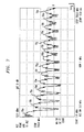
- FIG. 7 shows a graph of the DAC output across 700 MHz of frequency spectrum from 1 MHz to 700 MHz.
- each interval 70a-n of the conversion rate or frequency includes a replica analog image (the fundamental analog image itself in interval 70a) and a mirror analog image of the fundamental analog image in zone 0.
- the analog images do not appear as in the examples above due to the limitations in the resolution of the spectrum analyzer across such a wide frequency span.
- FIG. 7 shows how the amplitude of the analog signal images decrease in amplitude with increasing frequency. In this example, the analog signal images decrease about 30 dB from the frequency interval 70a to the frequency interval 70n, following a sin x/x or sinc function deterioration in the amplitude of the analog images.
- a digital transmitter could reduce or remove any frequency conversion stages and remove a low pass filter at the output of the DAC by using analog signal image(s) at the desired frequency(ies) to produce analog signals at baseband, intermediate frequency (IF) and/or radio frequency (RF) for transmission.
- analog signal image(s) at the desired frequency(ies) to produce analog signals at baseband, intermediate frequency (IF) and/or radio frequency (RF) for transmission.
- IF intermediate frequency
- RF radio frequency
- different digital signals can be positioned within non-overlapping portions of the conversion bandwidth, and the different analog signal images or portions thereof at different analog baseband, IF and/or RF frequency signals can be used for transmitting the analog signals.
- the FM analog signal image from a first zone can be used to transmit the FM analog signal at RF
- the CDMA analog signal image from a second zone can be used to transmit the CDMA analog signal image over the air at RF. Therefore, the digital transmitter 20 (FIG. 2) can use the conversion bandwidth available in a single DAC to produce the RF analog signals from different RF frequency bands.
- the transmitter can be implemented in different ways to use the potential conversion bandwidth of a DAC 22 (FIG. 2a).
- a B band service provider digital signals for communications to be transmitted over the cellular base station transmit "B" and B' band (880-890 and 891.5-894 MHz) could be positioned in a total 14 MHz portion (if the relationship between the B and B' bands at RF is maintained in the B and B' bands in the digital domain) of the conversion bandwidth of the DAC 22 such that the resulting cellular analog signal bandwidth in zone 0 folds out to the cellular base station transmit band at 880-894 MHz.
- Digital signals for communications over a "D block" of the PCS base station transmit band (1945-1950 MHz) could be positioned within a 5 MHz portion of the conversion bandwidth which does not overlap with the cellular band such that the resulting PCS analog signal bandwidth in zone 0 folds out to the D block of the PCS base station transmit band at 1945-1950 MHz).
- digital signal information to be transmitted in the FM radio frequency band (88 to 108 MHz) could be positioned in a 20 MHz portion of the conversion bandwidth of the DAC 22 such that the resulting FM radio analog signal bandwidth is at or folds out to the FM radio band at 88 to 108 MHz.
- the total bandwidth of the RF analog signals in the different portions of the conversion bandwidth is 39 MHz after adding the cellular (14 MHz), the D block for PCS (5MHz) bands and the FM radio (20MHz).
- a conversion rate for the DAC 22 is used such that the conversion bandwidth is sufficient to handle the 39 MHz bandwidth of the RF analog signals.
- the conversion rate must be at least 78 MHz.
- the conversion rate for the DAC 22 is selected such that the different frequency bands are replicated in the desired frequency bands.
- the selection of the appropriate conversion rate is effected by the relative positioning of the different frequency bands from the conversion bandwidth to the desired frequency bands for the analog images.
- a conversion rate is selected to provide guard bands between the signals of the different frequency bands.
- FIG. 8 shows the resulting DAC output if the DAC has a conversion rate of 600 MHz with a corresponding conversion bandwidth of 300 MHz.
- the FM digital signal bandwidth can be positioned at 88 to 108 MHz, the PCS D block digital bandwidth at 145 - 150 MHz and the cellular B band digital bandwidth at 280-294 MHz.
- the DAC converts the digital spectrum in analog form resulting in a fundamental image 80 within the conversion bandwidth with fundamental analog signal image 82 at 88 to 108 MHz (FM), fundamental analog signal image 84 at 145 - 150 MHz (PCS D-block) and fundamental analog signal image 86 at 280-294 MHz.
- the conversion bandwidth folds about itself at intervals of one-half the conversion rate to produce analog images or zones 88a-g.
- the fundamental FM analog signal image 82 is at the appropriate frequency for transmission.
- the digital transmitter can use the fundamental FM analog signal image 82 for transmission over the air at 88 to 108 MHz.
- the output of the DAC includes FM analog signal images 90a-g which will not be used in this example.
- the mirroring/de-mirroring of signal bandwidth can be readily performed, for example by swapping in-phase (I) and quadrature (Q) components prior to or during conversion into the digital domain such that the mirrored analog signal images for transmission have the desired spectral relationship.
- the desired spectral relationship for mirrored analog signal images can be achieved by manipulating the digital signal(s) as would be understood by one of skill in the art such that the resulting mirrored analog signal images for transmission have the desired spectral position (e.g. de-mirrored).
- the receiver could receive the mirrored analog signal images and perform the de-mirroring or folding of the spectrum to achieve the desired analog signal images.
- the digital transmitter can use the fundamental FM analog signal image at 88 to 108 MHz for amplification and transmission.
- the cellular B-band analog signal image 94b falls on the transmission frequency of 880 to 894 MHz for the cellular B band, and the analog signal image 94b can be amplified and transmitted into the cellular B band.
- the PCS D-block analog signal image 92f falls on the transmission frequency of 1945-1950 MHz for the PCS D-block, and the analog signal image 92f can be amplified and transmitted into the PCS D-block.
- the output of the DAC 22 is received by the coupling network 30 in which a bandpass filter 32a could correspond to the FM broadcast band of 88 to 108 MHz.
- the filter 32a allows the frequencies between 88 and 108 MHz to pass onto the path 31a while attenuating other frequencies.
- the FM analog signal image 82 on the path 31a is amplified by the amplifier 34a and transmitted from antenna 36a.
- the bandpass filter 32b could correspond to the cellular B-band frequency or portion thereof and allow frequencies between 880-894 MHz to pass onto the path 31b while attenuating other frequencies.
- the cellular B-band analog signal image 94b on the path 31b is amplified by the amplifier 34b and transmitted from the antenna 36b.
- the bandpass filter 32x could correspond to the PCS D-block of frequency or portion thereof and allow frequencies between 1945-1950 MHz to pass onto the path 31y while attenuating other frequencies.
- the PCS D-block analog signal image 92f on the path 31y is amplified by the amplifier 34y and transmitted from the antenna 36z.
- the transmitter according to principles of the present invention eliminates the need for a frequency conversion stage (mixer/LO combination) on any of the paths 31a-x (FIG. 2a).
- a transmitter without a mixer/LO combination has many advantages in addition to reducing costs. For example, without a fixed local oscillator(s) (LO) in the frequency conversion stage(s), DC power consumption is reduced as well as cost and size. Filter requirements at the IF can be reduced and/or eliminated as well as filter requirements for the removal of LO radiation. Because a mixer is not required, spurious mixer products as well as intermodulation distortion produced by the mixer are removed, thereby improving the spurious free dynamic range and shielding requirements. Additionally, losses introduced by the mixer are removed which reduce the required channel gain and which improve the gain linearity.
- LO local oscillator
- the transmitter can increase the utilization of the potential conversion bandwidth provided by the DAC 22 to transmit RF analog signals in different frequency bands separated by large frequency differences.
- the entire FM radio spectrum, the B band for the cellular spectrum and the D block for the PCS spectrum were positioned in the digital domain within the conversion bandwidth of 300 MHz and converted into analog form using a single DAC having a conversion rate of 600 MHz.
- the DAC produces a fundamental analog image of the converted digital signals in the conversion bandwidth as well as replica and mirror images of the fundamental image which can be used for to produce analog signals at the appropriate transmission frequencies.
- different conversion rates can be used to increase or decrease the conversion bandwidth, for example to provide extra bandwidth or guard bands between the signals of the different frequency bands.
- the transmitter according to the principles of the present invention can transmit signals from systems using different, the same or no multiple access techniques, using the same and/or different modulation techniques, and/or using different and/or contiguous frequency bands or schemes in a single DAC converter without frequency conversion to the RF or transmit frequency bands.
- the analog signals can be characterized as wideband, broadband and/or narrowband.
- Alternative embodiments could have frequency conversion of the analog signal image(s).
- an analog signal image could be at an intermediate frequency which requires frequency conversion.
- an analog signal mirror or replica image could be frequency converted to radio or transmission frequency to reduce or eliminate a frequency conversion stage or to fine tune the positioning of the analog signal images at radio or transmission frequency.
- an AM broadcast radio frequency band (550-1600 kHz) can be added to the combined or composite digital signal, and the DAC 22 can convert the digital signals in the AM radio frequency band.
- the AM radio frequency band would be located in the kilohertz range of the conversion bandwidth.
- the transmitter according to the principles of the present invention could use analog signal images from the conversion process to transmit signals from different sources simultaneously, such as the cellular or PCS networks, AM and/or FM broadcast radio stations, satellite systems, or other systems based on different physical mediums for transmission.
- an embodiment of the transmitter system can be used to transmit signals according to systems using different protocols and RF frequencies, such as a North American TDMA system, a Global System For Mobile Communication (GSM) system, a code division multiple access (CDMA) system, frequency division multiple access (FDMA) systems, FM radio and/or AM radio.
- GSM Global System For Mobile Communication
- CDMA code division multiple access
- FDMA frequency division multiple access
- FM radio FM radio and/or AM radio.
- the embodiments of the transmitter according to the principles of the present invention have been described as using multiple distinct analog signal images to transmit analog signals in non-contiguous frequency bands.
- the digital transmitter according to the principles of the present invention can use a conversion rate or digital signal frequency(ies), for example which is set dynamically, periodically, at subscription, as controlled in the field or during manufacture, to produce analog signal images for the transmission of analog signals in a particular frequency band and/or using a particular multiple access technique, for example CDMA at the cellular B band.
- a conversion rate or digital signal frequency(ies) for example which is set dynamically, periodically, at subscription, as controlled in the field or during manufacture, to produce analog signal images for the transmission of analog signals in a particular frequency band and/or using a particular multiple access technique, for example CDMA at the cellular B band.
- CDMA Code Division Multiple Access
- the same hardware can be used for digital transmitters which transmit analog signals at different frequencies and/or using different multiple access techniques or protocols.
- the desired transmission frequencies can be set at manufacture or changed periodically, dynamically or as directed or controlled by setting and/or using different conversion rates and/or digital signal frequency(ies).
- the desired protocol or multiple access technique can be provided via stored or downloaded software and/or transmitter reconfiguration, for example using programmable logic devices and the like, depending on the embodiment as would be understood by one of skill in the art.
- the frequency band(s) for transmission have been associated with base station transmit frequencies, but the transmitter architecture according to the principles of the present invention can be used in wireless units, such as mobile units, transmitting information at different frequency band(s), for example, transmitting on PCS and/or cellular frequencies using the same and/or different multiple access systems in attempts to gain access to one or a plurality of wireless communications systems.
- the digital transmitter could continue transmissions at one or a plurality of the wireless communications systems over the corresponding frequency band(s).
- a wireless unit or wireless base station could dynamically, periodically, during operation or at manufacture or installation adjust the conversion rate and/or the frequency(ies) of the digital signal(s) to properly position the analog signal image(s) for transmission in the desired band(s).
- This exemplifies the increased flexibility of this transmitter architecture which can provide changing and/or different operating frequency(ies) because it does not require analog frequency conversion on transmit paths which are generally fixed after manufacture and/or installation.
- the transmitter system has been described using particular configurations of distinct components, but it should be understood that the transmitter system and portions thereof can be implemented in application specific integrated circuits, software-driven processing circuitry, firmware, programmable logic devices, hardware or other arrangements of discrete components as would be understood by one of ordinary skill in the art with the benefit of this disclosure.
- the transmitter architecture can use different components which together perform similar functions when compared to the circuitry shown. What has been described is merely illustrative of the application of the principles of the present invention. Those skilled in the art will readily recognize that these and various other modifications, arrangements and methods can be made to the present invention without strictly following the exemplary applications illustrated and described herein and without departing from the spirit and scope of the present invention.
Abstract

Description
- This invention relates to wireless communications and, more particularly, to a digital transmitter architecture for a wireless communications system.
- The service area of a wireless communications system is partitioned into connected service domains known as cells, where wireless units communicate via radio links with a base station (BS) serving the cell. The base station is coupled to a land network, for example through a Mobile Switching Center (MSC) which is connected to a plurality of base stations dispersed throughout the service area. In the wireless communications industry, service providers are often granted two or more non-contiguous or segregated frequency bands to be used for the wireless transmission and reception of RF communications channels. For example, in the United States, a base station for an "A" band provider for cellular communications receives frequency channels within the A (825-835 MHz), A' (845-846.5 MHz) and A" (824-825MHz) bands, and transmit on frequency channels within the A (870-880 MHz), A' (890-891.5 MHz) and A" (869-870MHz) bands. A base station for a B band provider receives frequency channels within the B (835-845MHz) and B'(846.5-849 MHz) frequency bands, and transmits on frequency channels within the B (880-890MHz) and B'(891.5-894 MHz) frequency bands. Additionally, a base station for a Personal Communications Systems (PCS) provider may receive frequency channels from wireless units on one or more blocks of the PCS band (1850MHz-1910MHz), and transmit on frequency channels on one or more blocks of the PCS band (1930-1990 MHz).
- In a typical transmitter architecture, the baseband information signals are digital signals which are provided to signal processing units (SPUs). The SPUs take the baseband digital signals and perform encoding, error detection processing, bit interleaving and digital in-phase (I) and quadrature (Q) modulation on the digital signals. The resulting digital (I/Q) modulated intermediate frequency (IF) signals are summed together and provided to a digital to analog converter (DAC). The DAC converts the digital IF signals into analog IF signals which are frequency upconverted using analog mixers into analog radio frequency (RF) signals for transmission at the appropriate frequency bands. A common transmitter for the simultaneous processing and transmission of signals within the non-contiguous frequency bands could reduce system hardware costs.
- Currently, the transmission systems have an analog low pass filter to remove periodic images of the analog IF signals produced at higher frequencies by the DAC as a result of the digital to analog conversion process. When the digital IF spectrum is converted into the analog domain by a DAC at a conversion rate, the signal bandwidth rotates, or folds, periodically at multiples of one-half the conversion frequency. As such, replica and mirror images of the signal bandwidth are periodically repeated at frequency intervals corresponding to the conversion rate of the DAC.
- For example, FIG. 1 shows the analog filter requirements for a DAC where the fundamental analog output frequency f0 = 10 MHz, which corresponds to the digital input frequency of 10 MHz, and the conversion rate is 30 megawords per second (Mwps) or 30 megasamples per second (Msps), which is equivalent to a conversion frequency of 30 MHz, for the top graph and a conversion rate of 60 Mwps or 60Msps, which is equivalent to a conversion frequency of 60 MHz, for the bottom graph. The DAC converts the 10 MHz digital signal to a fundamental
analog signal image 12a at 10MHz. With a conversion rate of 30 MHz, the DAC outputs amirror image 14a at 20 MHz of the fundamentalanalog signal 12a. Because the signal bandwidth and mirror images of the signal bandwidth are periodically repeated at frequency intervals corresponding to the conversion rate, areplica image 12b of the analog signal is produced at 40 MHz, and amirror image 14b is produced at 50 MHz along with areplica image 12c at 70 MHz and amirror image 14c at 80 MHz. For a DAC with a conversion rate of 30 MHz, current design practices use an analog low pass filter (LPF) to remove anyimages 12b-c and 14a-c and so on from the output of the DAC, leaving the fundamental 10MHz analog signal image for upconversion to the appropriate RF frequency for transmission. - With a conversion rate of 60 MHz (or 60 Msps or 60 Mwps), the DAC outputs the fundamental 10 MHz
analog signal image 16a along with amirror image 18a at 50 MHz. Because the signal bandwidth and mirror images of the signal bandwidth are periodically repeated at frequency intervals corresponding to the conversion rate, areplica image 16b of the analog signal is produced at 70 MHz, and amirror image 18b is produced at 110 MHz. As described above, current design practices use an analog low pass filter (LPF) to remove anyimages - As technology improves, the conversion rate for DACs increases. Current transmitter architectures, however, do not take advantage of the potential cost savings and flexibility which could be provided by the DACs.
- The present invention is a digital transmitter which converts a digital signal into analog form with a digital to analog converter (DAC) and uses an analog signal image produced from the DAC to provide an analog signal at a transmission frequency and/or uses a projected analog signal image to produce analog signals for transmission. Rather than removing analog signal images with a low pass filter at the output of the DAC and/or using analog signal images and analog mixers for frequency conversion, the digital transmitter uses the analog signal images from the DAC to produce the analog signals at the desired frequency/frequencies. By setting and/or adjusting the conversion rate for the DAC and/or the digital signal frequency/frequencies, the analog signal images produced from the DAC can be positioned in the desired frequency band(s). For example, the digital transmitter can position the digital signals within non-overlapping portions of a conversion bandwidth defined as one-half the conversion rate for the DAC. When the digital signals are converted into analog form, the DAC produces analog signal images periodically repeated at multiples of one-half the conversion rate such that analog signal images are produced at the appropriate frequency band(s) for amplification and transmission.
- Other aspects and advantages of the present invention may become apparent upon reading the following detailed description and upon reference to the drawings in which:
- FIG. 1 shows a general graph of how the prior art teaches to filter out analog signal images from the output of DACs;
- FIG. 2a shows a general block diagram of an embodiment of the transmitter according to the principles of the present invention, and FIG. 2b shows a graph of the output of the DAC for the transmitter of FIG. 2a;
- FIG. 3 shows a frequency domain graph of example digital signals to be converted into analog form and transmitted according to principles of the present invention;
- FIG. 4 shows the analog signal images in a span of 0 to 50 MHz at the output of the DAC resulting from the conversion of the digital signals of FIG. 3 into analog form using a conversion frequency of 50 MHz;
- FIG. 5 shows the analog signal images in a span of 0 to 100 MHz at the output of the DAC resulting from the conversion of the digital signals of FIG. 3 into analog form using a conversion frequency of 50 MHz;
- FIG. 6 shows the analog signal images in a span of 450 to 550 MHz at the output of the DAC resulting from the conversion of the digital signals of FIG. 3 into analog form using a conversion frequency of 50 MHz;
- FIG. 7 shows the analog signal images in a span of 0 to 700 MHz at the output of the DAC resulting from the conversion of the digital signals of FIG. 3 into analog form using a conversion frequency of 50 MHz; and
- FIG. 8 shows the analog signal images in a span of 0 to 2400 MHz at the output of the DAC resulting from the conversion of example PCS, cellular and FM digital signals into analog form using a conversion frequency of 600 MHz
-
- Illustrative embodiments are described below of a digital transmitter system having a digital to analog converter (DAC) to convert a digital signal(s) into analog form and using resulting analog signal image(s) to produce analog signal(s) for transmission. FIG. 2a shows a
digital transmitter 20 including aDAC 22 which receives at least one digital signal. TheDAC 22 converts the digital signal spectrum at a conversion rate fc. The conversion rate fc for the DAC is chosen such that the conversion bandwidth from 0 Hz to one-half of the conversion rate encompasses the bandwidth of the digital signal(s). The higher the conversion rate, the wider is the conversion bandwidth. If the digital signal bandwidth is greater than one-half the conversion rate, an undesirable overlapping between the projected images can occur. - As shown in FIG. 2B, the DAC converts the digital signals (F1-FN) using a conversion rate fc encompassing the digital signals from frequencies F1 to FN within a conversion bandwidth equal to one-half the conversion rate. In converting the digital spectrum into analog form at the conversion rate fc, the conversion bandwidth or fundamental
analog image 24 rotates or folds periodically at multiples of one-half the conversion frequency fc to produce a mirrored first projectedanalog image 26a, a replica second projectedanalog image 26b and a mirrored third projectedanalog image 26c of thefundamental image 24 containing the analog signals (F1-FN). Analog image can refer to the fundamental analog image produced from 0 Hz to one-half the conversion rate by converting the digital spectrum into analog form at the conversion rate as well as any projected replica or mirrored analog images of the fundamental analog image. Analog signal image can refer to a fundamental analog signal image as well as the corresponding projected analog signal images of the fundamental analog signal image resulting from converting a particular digital signal(s) within the digital signal spectrum into analog form. - By setting the conversion rate and/or the digital signal frequencies, the converted digital signals can be positioned at frequencies such that when the digital signals are converted into analog form, the analog signal images fall at the desired frequencies. If the fundamental analog signal image is at the desired transmission frequency, the fundamental analog signal image can be directly amplified and transmitted at the desired transmission frequency without frequency conversion in the analog domain. If the fundamental analog signal image is not at the desired transmission frequency, the digital transmitter can use the subsequent analog signal images which are projected from the fundamental analog signal image to produce the desired analog signal for transmission. As such, rather than filtering the analog signal images from the fundamental analog signal image, a projected analog signal image which falls on a desired transmission frequency can be directly amplified and transmitted. The projected analog signal image could also fall on a desired intermediate frequency (IF) which can be frequency converted to an intermediate or eventually a transmission frequency for amplification and transmission. By using a projected analog signal image at a desired intermediate frequency, the number of frequency conversion stages can be reduced. Projected analog signal images refers to a replica or mirror image of the fundamental analog signal image. Thus, the digital transmitter does not need to filter out the analog images nor rely only on frequency conversion in the analog domain to position the analog signals in the appropriate transmission band(s).
- The digital transmitter provides flexibility and efficient use of the available conversion bandwidth established by the conversion rate. For example, if the digital signals that are converted into analog form are to be transmitted in non-contiguous frequency bands, the conversion bandwidth could encompass the non-contiguous bands if a high enough conversion rate is available. If not or if desired, the digital transmitter can position the digital signals within the conversion bandwidth at positions independent of the relative positioning between the corresponding analog signals at the transmission frequencies. For example, the digital signals can be positioned closer together in the conversion bandwidth than the corresponding analog signals at their transmission frequencies. After the digital transmitter converts the digital signals into analog form, analog signal images in different zones (or different multiples of one-half the conversion rate) can be used to produce analog signals in the non-contiguous transmission bands.
- Alternatively, a digital transmitter may be able to communicate on a plurality of wireless communications frequencies, such as PCS or cellular, and/or using a plurality of wireless communications protocols, such as CDMA, GSM, North American TDMA or others. As such, depending on the wireless communications frequency(ies) and/or wireless communication protocol(s) to be used by the digital transmitter (base station or wireless unit), the conversion rate to be used can be set and/or the position of the digital signal(s) adjusted such that the resulting analog signal image falls on the desired transmission frequency(ies). Moreover, when a wireless unit attempts to access a wireless communications system, the wireless unit may not have information on the type of wireless communication frequency/frequencies and/or protocol(s) used in the system, or the system could use a plurality of non-contiguous frequency band and/or protocols.
- To access and communicate with the wireless communication system, the wireless unit could set the digital signal frequencies and/or conversion rate to transmit analog signals simultaneously using different frequency bands and/or protocols. The wireless unit could transmit using one frequency band/protocol combination at a time for analog signal transmissions, for example by changing the conversion rate and/or digital signal frequency(ies) for each analog signal transmissions corresponding to at least each different frequency band. The digital signal frequency(ies) and/or conversion rates for the desired type of analog signal transmission could be, predetermined and set for a single frequency band/protocol configuration, predetermined and stored for a plurality of frequency/protocol configurations and/or determined or calculated in the wireless unit or base station or received from the wireless unit or the wireless communications system depending on the embodiment. Configuration settings could also include amplifier bias and/or predistortion settings.
- In the embodiment of FIG. 2a, a coupling network or signal
distribution network 30, such as a power divider or a N-plexer, receives the entire analog signal spectrum from theDAC 22 and combines and/or separates the analog signals or portions thereof and provides the analog signals onto transmission, amplification or channel branches orpaths 31a-x in a desired manner. For example, thepaths 31a-x can carry the analog signals for corresponding RF frequency bands, can carry analog signals to be transmitted on different antenna(s) or sets of antennas, and/or can have copies of the analog signals of different or contiguous frequency bands. Depending on the embodiment, thecoupling network 30 can simply include direct connection(s) from theDAC 22 to eachfilter 32a-x, and eachfilter 32a-x is connected to acorresponding antenna 36a-x. If thetransmitter 20 has a single transmission branch 31, thecoupling network 30 includes a connection from theDAC 22 through a filter 32, an amplifier 34 to an antenna 36. The numbers ofpaths 31a-x, filters 32a-x,amplifiers 34a-x andantennas 36a-x can be equal to or greater than one and can be different and/or equal to each other. - In any event, the
coupling network 30 provides the desired analog signals f1 to fN topaths 31a-x for amplification and transmission. In the embodiment of FIG. 2a,bandpass filters 32a-32x of thecoupling network 30 allow the analog signals at the desired frequencies fl to fN to pass on thecorresponding path 31a-x while attenuating all other signal frequencies. The desired analog signals f1 to fN are amplified byamplifiers 34a-x and transmitted byantennas 36a-x. As shown in FIG. 2b, the desired frequencies f1-fN for the analog signals are at different portions of the analog signal spectrum. For example, the analog signal f1 for amplification and transmission is actually in a portion of the analog signal bandwidth (F1-FN) in the conversion bandwidth or fundamental analog image between 0 Hz and .5fc. The analog signal fN is in a portion of thereplica image 26b of the n-1 multiple of the conversion rate fc. After the analog signals are isolated at the desired freguencies (fl-fN), theamplifiers 34a-x amplify the analog signals at the desired frequencies for transmission through theantennas 36a-x. - In the embodiment of FIG. 2a, the
transmitter 20 includes signal processing units (SPUs) 42a-i which receive m digital signals or streams Dl to Dm, such as baseband digital information signals. An SPU can receive a single digital signal, a plurality of digital signals and/or a composite digital signal which includes a plurality of digital signals. In this embodiment, eachSPU 42a-i receives at least one digital signal. If anSPU 42a-i receives a digital signal comprising a plurality of digital signals (such as digital baseband information signals for 10 voice calls at 8-10 kilobits per second), the digital signals are added together. EachSPU 42a-i can encode the digital signal(s), add error correction information to the digital signal(s), perform bit interleaving, and perform in-phase (I) and quadrature (Q) modulation on the digital signal(s) and perform digital frequency conversion (up or down) to produce a digital intermediate frequency (IF) signal. If the position of the digital signal(s) within the conversion bandwidth needs to be adjusted, a digital frequency converter, for example using a numerically controlled oscillator (NCO) and digital mixer for frequency spectrum positioning, can tune the baseband digital signal(s) or the digital IF signal for proper positioning of the digital signal(s) within the conversion bandwidth for the DAC such that the resulting analog image falls within the desired frequency band at the output of theDAC 22. - In the embodiment of FIG. 2a, an
SPU 42a-i produces a digital I/Q modulated signal (digital intermediate frequency (IF)), resulting from the processing of at least one digital signal, onto correspondingbuses 44a-i. Thebuses 44a-i are provided to acombiner 46, such as a field programmable gate array FPGA acting as a bus summer. Thecombiner 46 aligns the clock and data edges of the digital signals from thedifferent buses 44a-i and sums the digital signals on thebuses 44a-i onto abus 48. In one example, eachbus 44a-i is an 18 bit bus handling 68 megawords per second (Mwps) of digital data, where a word is the width of the bus, and thebus 48 is a 14 bit bus handling 68 Mwps. If there are five SPU's 48a-i, and eachSPU 44a-i handles up to 10 voice calls, thebus 48 can carry a digital signal for up to 50 voice calls. Thebus 48 provides the composite digital signal to theDAC 22, which can be a 14 bit DAC performing at a conversion rate of 68 MHz. In this example, due to the fact that the DAC is a 14 bit device and each bus 44 a-i to be summed is 18 bits (with sign bits), theFPGA 46 does a truncation on the resulting sum of theincoming buses 44a-i. This truncation is usually referred to as a gain adjustment. - As mentioned above, a conversion rate for the
DAC 22 is selected such that the total bandwidth of the digital information signals is encompassed by the conversion bandwidth which is at least one-half the conversion rate or frequency. Additionally, the different digital signals should occupy non-overlapping portions of the conversion bandwidth which fold out to produce analog signal image(s) at the desired frequency bands for each of the corresponding digital signals. The analog signal images at the desired frequency bands can be used to produce analog signals for transmission at RF. - FIG. 3 shows a frequency spectrum analysis from 0 Hz to 50 MHz of a composite digital signal. The graph can be obtained by performing a fourier transform on the composite digital signal as would be understood by one of skill in the art. The composite digital signal, which itself can be referred to as a digital signal, comprises a code division multiple access (CDMA)
digital signal 50 at a center frequency of 10 MHz with about a 2MHz bandwidth and an amplitude of about -10 dBm and a frequency modulated (FM)digital signal 52 at a center frequency of 20 MHz with about 7 MHz bandwidth and an amplitude of -4 dBm. The composite digital signal is provided to a DAC for conversion into analog form. - FIG. 4 shows a frequency spectrum analysis from 0 to 50 MHz of the output of the DAC resulting from the composite digital signal of FIG. 3 with the DAC operating at a conversion rate or frequency fc of 50 MHz. From 0 Hz to one-half fc, which can be referred to as the conversion bandwidth or
zone 0, the fundamentalanalog signal images digital signals 50 and 52 (FIG. 3). As such, the fundamentalanalog signal image 60 corresponds to CDMAdigital signal 50 of FIG. 3, and the fundamentalanalog signal image 62 corresponds to the FMdigital signal 62 of FIG. 3. As shown, theanalog signal image 60 remains at a center frequency of about 10 MHz with a bandwidth of about 2 MHz while the amplitude is at about -26 dBm. Theanalog signal image 62 remains at a center frequency of about 20 MHz with a bandwidth of about 7 MHz while the amplitude is at about -22 dBm. - As mentioned above, the spectrum within the conversion bandwidth folds up about intervals of ½ the conversion rate to produce projected replica and mirror analog images of the fundamental image. In FIG. 4, the conversion bandwidth or
zone 0 folds about 25 MHz (one-half the conversion rate) to produce a mirroredanalog image 26a of thefundamental analog image 24 from about 25 MHz to 50MHz which can be referred to aszone 1. Inzone 1,analog signal image 64a is the mirror image of the FManalog signal image 62. Theanalog signal image 64a has a center frequency of about 30 MHz with the bandwidth remaining at about 7 MHz while the amplitude is at about -25 dBm.Analog signal image 66a is the mirror image of the CDMAanalog signal image 60. Theanalog signal image 66a has a center frequency of 40 MHz with the bandwidth remaining at about 2MHz while the amplitude is at about -38 dBm. Amplitude differences between figures can result from setting changes on the spectrum analyzer between the figures, such as the resolution bandwidth, video bandwidth (VBW), sweep rate. span and start/stop. The setting changes may effect the resolution and accuracy of the spectrum analyzer. - FIG. 5 shows a graph of the frequency spectrum from 0 to 100 MHz with the spectrum analyzer set at a higher sensitivity. As mentioned above, replica and mirror projected analog images of the
conversion bandwidth 24 or zone 0 (fundamental analog image) containing the fundamental analog signal image(s) are repeated at frequency intervals of the conversion frequency. In FIG. 5,zone 1 is a mirrored first projectedanalog image 26a of the fundamental analog image orzone 0;zone 2 is a replica second projectedanalog image 26b of the fundamental analog image orzone 0; andzone 3 is a mirrored third projectedanalog image 26c of the fundamental analog image orzone 0. As such,analog signal image 66b inzone 2 is a replica of CDMAanalog signal image 60, and analog signal image 64b inzone 2 is a replica of FManalog signal image 62. The CDMAanalog signal image 66b is at a center frequency of about 60 MHz with the bandwidth remaining the same and the amplitude about 15 dB less. The FM analog signal image 64b is at a center frequency of about 70 MHz with the bandwidth remaining the same and the amplitude about 12 dB less. Inzone 3, theanalog signal image 66c inzone 3 is a mirror image of CDMAanalog signal image 60, andanalog signal image 64c inzone 3 is a mirror image of FManalog signal image 62. The FManalog signal image 64c is at center frequency of about 80 MHz with the bandwidth remaining the same and the amplitude about 1 dB less than the FM analog signal image 64b inzone 2. The CDMAanalog signal image 66c is at a center frequency of about 90 MHz with the bandwidth remaining the same and the amplitude about 4 dB less than the CDMAanalog signal image 66b inzone 2. - FIG. 6 is a graph showing the frequency spectrum from 450 MHz to 550 MHz containing projected
analog images 26r-u. In FIG. 6, projectedanalog image 26r is the eighteenth (18th) projected image orzone 18 of the fundamental analog image orzone 0. Theanalog image 26r orzone 18 is a replica of the fundamental analog image orzone 0. CDMAanalog signal image 66r is a replica of the CDMA analog signal image 60 (FIG. 5), and FManalog signal image 64r is a replica of the FM analog signal image 62 (FIG. 5). The CDMAanalog signal image 66r has a center frequency of about 460 MHz and has an amplitude which is shown as about 39 dB below the amplitude of the CDMA analog signal 60 (FIG.5). The FManalog signal image 64r has a center frequency of about 470 MHz and has an amplitude which is shown as about 29 dB less than the amplitude of the FM analog signal 62 (FIG.5). - The
analog image 26s is the nineteenth (19th) projected analog image orzone 19 of the fundamental analog image orzone 0. Theanalog image 26s orzone 19 is a mirror image of the fundamental analog image orzone 0. CDMAanalog signal image 66s is a mirror image of the CDMA analog signal image 60 (FIG. 5), and FManalog signal image 64s is a mirror image of the FM analog signal image 62 (FIG. 5). The CDMAanalog signal image 66s has a center frequency of about 490 MHz and has an amplitude which is shown as slightly less than the amplitude of the CDMAanalog signal image 66r. The FManalog signal image 64s has a center frequency of about 480 MHz and has an amplitude which is shown as about 1 dB less than the amplitude of the FManalog signal image 64r. - The projected analog image 26t is the twentieth (20th) image or
zone 20 of the fundamental image orzone 0. The projected analog image 26t orzone 20 is a replica of the fundamental analog image orzone 0 where CDMAanalog signal image 66t is a replica of the CDMA analog signal image 60 (FIG. 5), and FM analog signal image 64t is a replica of the FM analog signal 62 (FIG. 5). The CDMAanalog signal image 66t has a center frequency of about 510 MHz and has an amplitude which is shown as about the same as the CDMAanalog signal image 66s. The FM analog signal image 64t has a center frequency of about 520 MHz and has an amplitude which is shown as about 3dB less than the amplitude of the FManalog signal image 64s. - Finally, the projected
analog image 26u is the twenty first (21st) projected analog image orzone 21 of the fundamental analog image orzone 0. Theanalog image 26u orzone 21 is a mirror image of the fundamental analog image orzone 0. CDMAanalog signal image 66u is a mirror image of the CDMA analog signal image 60 (FIG. 5), and FManalog signal image 64u is a mirror image of the FM analog signal image 62 (FIG. 5). The CDMAanalog signal image 66u has a center frequency of about 540 MHz and has an amplitude which is shown as slightly less than amplitude of the CDMAanalog signal image 66t. The FManalog signal image 64u has a center frequency of about 530 MHz and has an amplitude which is shown as about the same as the amplitude of the FM analog signal image 64t. - As the analog signal images increase in frequency, the amplitudes for the analog signal images decrease, but a low cost amplifier and/or amplifier stages together with any appropriate filtering can be used to amplify the analog signal images while maintaining the noise floor low as would be understood by one of ordinary skill in the art, for example by using band-limiting filtering to maintain the signal to noise ratio (SNR). Additionally, amplitude equalization filtering in the digital or analog domain can be used to compensate for any amplitude reduction and/or distortion produced by the DAC on the analog signal image, for example filtering implementing an inverse of a sin x/x function or other function to compensate for a sin x/x or other effect introduced by the DAC onto the analog signal images at the desired frequencies for the analog signal images.
- FIG. 7 shows a graph of the DAC output across 700 MHz of frequency spectrum from 1 MHz to 700 MHz. As mentioned above, each
interval 70a-n of the conversion rate or frequency includes a replica analog image (the fundamental analog image itself ininterval 70a) and a mirror analog image of the fundamental analog image inzone 0. The analog images do not appear as in the examples above due to the limitations in the resolution of the spectrum analyzer across such a wide frequency span. FIG. 7 shows how the amplitude of the analog signal images decrease in amplitude with increasing frequency. In this example, the analog signal images decrease about 30 dB from thefrequency interval 70a to thefrequency interval 70n, following a sin x/x or sinc function deterioration in the amplitude of the analog images. - Thus, a digital transmitter according to the principles of the present invention could reduce or remove any frequency conversion stages and remove a low pass filter at the output of the DAC by using analog signal image(s) at the desired frequency(ies) to produce analog signals at baseband, intermediate frequency (IF) and/or radio frequency (RF) for transmission. Additionally, depending on the conversion rate used for the DAC, different digital signals can be positioned within non-overlapping portions of the conversion bandwidth, and the different analog signal images or portions thereof at different analog baseband, IF and/or RF frequency signals can be used for transmitting the analog signals. For example, in the example above, the FM analog signal image from a first zone can be used to transmit the FM analog signal at RF, and the CDMA analog signal image from a second zone can be used to transmit the CDMA analog signal image over the air at RF. Therefore, the digital transmitter 20 (FIG. 2) can use the conversion bandwidth available in a single DAC to produce the RF analog signals from different RF frequency bands.
- Depending on the embodiment and due to the flexibility of the digital transmitter according to the principles of the present invention, the transmitter can be implemented in different ways to use the potential conversion bandwidth of a DAC 22 (FIG. 2a). For example, for a B band service provider, digital signals for communications to be transmitted over the cellular base station transmit "B" and B' band (880-890 and 891.5-894 MHz) could be positioned in a total 14 MHz portion (if the relationship between the B and B' bands at RF is maintained in the B and B' bands in the digital domain) of the conversion bandwidth of the
DAC 22 such that the resulting cellular analog signal bandwidth inzone 0 folds out to the cellular base station transmit band at 880-894 MHz. Digital signals for communications over a "D block" of the PCS base station transmit band (1945-1950 MHz) could be positioned within a 5 MHz portion of the conversion bandwidth which does not overlap with the cellular band such that the resulting PCS analog signal bandwidth inzone 0 folds out to the D block of the PCS base station transmit band at 1945-1950 MHz). Additionally, in this example, digital signal information to be transmitted in the FM radio frequency band (88 to 108 MHz) could be positioned in a 20 MHz portion of the conversion bandwidth of theDAC 22 such that the resulting FM radio analog signal bandwidth is at or folds out to the FM radio band at 88 to 108 MHz. - In this example, the total bandwidth of the RF analog signals in the different portions of the conversion bandwidth is 39 MHz after adding the cellular (14 MHz), the D block for PCS (5MHz) bands and the FM radio (20MHz). As such, a conversion rate for the
DAC 22 is used such that the conversion bandwidth is sufficient to handle the 39 MHz bandwidth of the RF analog signals. For example, at a bare minimum for 39 MHz of bandwidth, the conversion rate must be at least 78 MHz. Additionally, as would be understood by one of skill in the art with the benefit of this disclosure, the conversion rate for theDAC 22 is selected such that the different frequency bands are replicated in the desired frequency bands. As such, the selection of the appropriate conversion rate is effected by the relative positioning of the different frequency bands from the conversion bandwidth to the desired frequency bands for the analog images. In practice, a conversion rate is selected to provide guard bands between the signals of the different frequency bands. - In an illustrative example, FIG. 8 shows the resulting DAC output if the DAC has a conversion rate of 600 MHz with a corresponding conversion bandwidth of 300 MHz. Within the conversion bandwidth, the FM digital signal bandwidth can be positioned at 88 to 108 MHz, the PCS D block digital bandwidth at 145 - 150 MHz and the cellular B band digital bandwidth at 280-294 MHz. The DAC converts the digital spectrum in analog form resulting in a
fundamental image 80 within the conversion bandwidth with fundamentalanalog signal image 82 at 88 to 108 MHz (FM), fundamentalanalog signal image 84 at 145 - 150 MHz (PCS D-block) and fundamentalanalog signal image 86 at 280-294 MHz. The conversion bandwidth folds about itself at intervals of one-half the conversion rate to produce analog images orzones 88a-g. The fundamental FManalog signal image 82 is at the appropriate frequency for transmission. As such the digital transmitter can use the fundamental FManalog signal image 82 for transmission over the air at 88 to 108 MHz. Within odd numberedzones 88 a, c, e and g, mirror images of zone 0 (80) are created while, in even-numberedzones 88 b, d, and f, replica images ofzone 0 are created. As such, in thezones 88a-g, the output of the DAC includes FManalog signal images 90a-g which will not be used in this example. The mirroring/de-mirroring of signal bandwidth can be readily performed, for example by swapping in-phase (I) and quadrature (Q) components prior to or during conversion into the digital domain such that the mirrored analog signal images for transmission have the desired spectral relationship. The desired spectral relationship for mirrored analog signal images can be achieved by manipulating the digital signal(s) as would be understood by one of skill in the art such that the resulting mirrored analog signal images for transmission have the desired spectral position (e.g. de-mirrored). Alternatively, the receiver could receive the mirrored analog signal images and perform the de-mirroring or folding of the spectrum to achieve the desired analog signal images. - Since the fundamental
analog signal image 82 is at the transmission frequency of 88 to 108 MHz, the digital transmitter can use the fundamental FM analog signal image at 88 to 108 MHz for amplification and transmission. The cellular B-bandanalog signal image 94b falls on the transmission frequency of 880 to 894 MHz for the cellular B band, and theanalog signal image 94b can be amplified and transmitted into the cellular B band. The PCS D-blockanalog signal image 92f falls on the transmission frequency of 1945-1950 MHz for the PCS D-block, and theanalog signal image 92f can be amplified and transmitted into the PCS D-block. - With particular reference to the embodiment of FIG. 2a and the example of FIG. 8, the output of the
DAC 22 is received by thecoupling network 30 in which abandpass filter 32a could correspond to the FM broadcast band of 88 to 108 MHz. As such, thefilter 32a allows the frequencies between 88 and 108 MHz to pass onto thepath 31a while attenuating other frequencies. The FManalog signal image 82 on thepath 31a is amplified by theamplifier 34a and transmitted fromantenna 36a. Thebandpass filter 32b could correspond to the cellular B-band frequency or portion thereof and allow frequencies between 880-894 MHz to pass onto thepath 31b while attenuating other frequencies. The cellular B-bandanalog signal image 94b on thepath 31b is amplified by theamplifier 34b and transmitted from theantenna 36b. Finally, thebandpass filter 32x could correspond to the PCS D-block of frequency or portion thereof and allow frequencies between 1945-1950 MHz to pass onto the path 31y while attenuating other frequencies. The PCS D-blockanalog signal image 92f on the path 31y is amplified by the amplifier 34y and transmitted from the antenna 36z. - As such, in this embodiment, the transmitter according to principles of the present invention eliminates the need for a frequency conversion stage (mixer/LO combination) on any of the
paths 31a-x (FIG. 2a). A transmitter without a mixer/LO combination has many advantages in addition to reducing costs. For example, without a fixed local oscillator(s) (LO) in the frequency conversion stage(s), DC power consumption is reduced as well as cost and size. Filter requirements at the IF can be reduced and/or eliminated as well as filter requirements for the removal of LO radiation. Because a mixer is not required, spurious mixer products as well as intermodulation distortion produced by the mixer are removed, thereby improving the spurious free dynamic range and shielding requirements. Additionally, losses introduced by the mixer are removed which reduce the required channel gain and which improve the gain linearity. - By properly selecting/setting the conversion rate for the
DAC 22, the transmitter according to the principles of the present invention can increase the utilization of the potential conversion bandwidth provided by theDAC 22 to transmit RF analog signals in different frequency bands separated by large frequency differences. In the above example, the entire FM radio spectrum, the B band for the cellular spectrum and the D block for the PCS spectrum were positioned in the digital domain within the conversion bandwidth of 300 MHz and converted into analog form using a single DAC having a conversion rate of 600 MHz. In converting the digital signals in the conversion bandwidth into analog signals, the DAC produces a fundamental analog image of the converted digital signals in the conversion bandwidth as well as replica and mirror images of the fundamental image which can be used for to produce analog signals at the appropriate transmission frequencies. In other embodiments, different conversion rates can be used to increase or decrease the conversion bandwidth, for example to provide extra bandwidth or guard bands between the signals of the different frequency bands. - Accordingly, the transmitter according to the principles of the present invention can transmit signals from systems using different, the same or no multiple access techniques, using the same and/or different modulation techniques, and/or using different and/or contiguous frequency bands or schemes in a single DAC converter without frequency conversion to the RF or transmit frequency bands. The analog signals can be characterized as wideband, broadband and/or narrowband. Alternative embodiments could have frequency conversion of the analog signal image(s). As such, an analog signal image could be at an intermediate frequency which requires frequency conversion. For example, an analog signal mirror or replica image could be frequency converted to radio or transmission frequency to reduce or eliminate a frequency conversion stage or to fine tune the positioning of the analog signal images at radio or transmission frequency.
- In addition to the embodiment described above, alternative configurations of the transmitter architecture according to the principles of the present invention are possible which omit and/or add components and/or use variations or portions of the described transmitter architecture. For example, an AM broadcast radio frequency band (550-1600 kHz) can be added to the combined or composite digital signal, and the
DAC 22 can convert the digital signals in the AM radio frequency band. The AM radio frequency band would be located in the kilohertz range of the conversion bandwidth. As such, the transmitter according to the principles of the present invention could use analog signal images from the conversion process to transmit signals from different sources simultaneously, such as the cellular or PCS networks, AM and/or FM broadcast radio stations, satellite systems, or other systems based on different physical mediums for transmission. As would be understood by one of ordinary skill in the art, the various components making up the transmitter architecture and their respective operating parameters and characteristics should be properly matched up to provide the proper operation. For example, an embodiment of the transmitter system can be used to transmit signals according to systems using different protocols and RF frequencies, such as a North American TDMA system, a Global System For Mobile Communication (GSM) system, a code division multiple access (CDMA) system, frequency division multiple access (FDMA) systems, FM radio and/or AM radio. - Additionally, the embodiments of the transmitter according to the principles of the present invention have been described as using multiple distinct analog signal images to transmit analog signals in non-contiguous frequency bands. The digital transmitter according to the principles of the present invention can use a conversion rate or digital signal frequency(ies), for example which is set dynamically, periodically, at subscription, as controlled in the field or during manufacture, to produce analog signal images for the transmission of analog signals in a particular frequency band and/or using a particular multiple access technique, for example CDMA at the cellular B band. As such, the same hardware can be used for digital transmitters which transmit analog signals at different frequencies and/or using different multiple access techniques or protocols. The desired transmission frequencies can be set at manufacture or changed periodically, dynamically or as directed or controlled by setting and/or using different conversion rates and/or digital signal frequency(ies). The desired protocol or multiple access technique can be provided via stored or downloaded software and/or transmitter reconfiguration, for example using programmable logic devices and the like, depending on the embodiment as would be understood by one of skill in the art.
- In the above example, the frequency band(s) for transmission have been associated with base station transmit frequencies, but the transmitter architecture according to the principles of the present invention can be used in wireless units, such as mobile units, transmitting information at different frequency band(s), for example, transmitting on PCS and/or cellular frequencies using the same and/or different multiple access systems in attempts to gain access to one or a plurality of wireless communications systems. After gaining access to one or a plurality of the wireless communications systems, the digital transmitter could continue transmissions at one or a plurality of the wireless communications systems over the corresponding frequency band(s). As such, depending on the available coverage or capabilities of the wireless unit, a wireless unit or wireless base station could dynamically, periodically, during operation or at manufacture or installation adjust the conversion rate and/or the frequency(ies) of the digital signal(s) to properly position the analog signal image(s) for transmission in the desired band(s). This exemplifies the increased flexibility of this transmitter architecture which can provide changing and/or different operating frequency(ies) because it does not require analog frequency conversion on transmit paths which are generally fixed after manufacture and/or installation.
- Furthermore, the transmitter system has been described using particular configurations of distinct components, but it should be understood that the transmitter system and portions thereof can be implemented in application specific integrated circuits, software-driven processing circuitry, firmware, programmable logic devices, hardware or other arrangements of discrete components as would be understood by one of ordinary skill in the art with the benefit of this disclosure. Although in the illustrative embodiment is shown with a particular circuitry, the transmitter architecture can use different components which together perform similar functions when compared to the circuitry shown. What has been described is merely illustrative of the application of the principles of the present invention. Those skilled in the art will readily recognize that these and various other modifications, arrangements and methods can be made to the present invention without strictly following the exemplary applications illustrated and described herein and without departing from the spirit and scope of the present invention.
Claims (10)
- A method of processing digital signals to be transmitted in analog form, said method CHARACTERIZED BY:converting a digital signal to produce a projected analog signal image (94b, 92f); andusing said projected analog signal image (94b, 92f) to produce analog signals for transmission.
- The method of claim 1 CHARACTERIZED BY:positioning said digital signal within a conversion bandwidth (80) defined as one-half the rate of said conversion frequency.
- The method of claim 1 CHARACTERIZED BY:receiving a plurality of digital signals;positioning said digital signals in non-overlapping portions of a conversion bandwidth (80) defined as one-half the rate of said conversion frequency;converting said digital signals to produce said projected analog signal images (94b, 92f) at frequencies greater than said conversion bandwidth (80); andusing said projected analog signal images (94b, 92f) for transmission.
- The method of claim 3 CHARACTERIZED IN THAT said step of using includes:providing a projected analog signal image onto a path (31a-x);amplifying said projected analog signal image on said path (31a-x); andtransmitting said amplified analog signal image using at least one antenna (36a-x).
- The method of claim 4 CHARACTERIZED IN THAT said steps of providing, amplifying and transmitting further include:providing a first projected analog signal image of a first frequency band on a first path (31a) and a second projected analog signal image of a second frequency band on a second path (31b);amplifying said first projected analog signal image on said first path and said second projected analog signal image on said second path; andtransmitting said first amplified analog signal image on a first antenna (36a) and said second amplified analog signal image on a second antenna (36b).
- The method of claim 5 CHARACTERIZED IN THAT said step of providing further includes:filtering a plurality of said projected analog signal images at different frequency bands to provide at least one projected analog signal image of a frequency band corresponding to each of a plurality of paths (31a-x).
- The method of claim 4 CHARACTERIZED IN THAT said steps of providing further includes:selectively producing on each of a plurality of paths (31a-x) at least one projected analog signal image of a frequency band corresponding to each of said plurality of paths (31a-x).
- The method of claim 1 further CHARACTERIZED BY:adjusting a conversion rate for converting said digital signal to produce said projected analog signal image at said frequency.
- The method of claim 1 further CHARACTERIZED BY:adjusting a digital frequency for said digital signal to be converted into analog form to produce said projected analog signal image at said frequency.
- A transmitter (20) CHARACTERIZED BY:a digital to analog converter (22) configured to receive a digital signal and convert said digital signal into analog form, thereby producing a projected analog signal image; andtransmitter circuitry (30, 31, 34, 36) configured to use said projected analog signal image to produce analog signals for transmission.
Applications Claiming Priority (2)
| Application Number | Priority Date | Filing Date | Title |
|---|---|---|---|
| US784846 | 2001-02-16 | ||
| US09/784,846 US6944238B2 (en) | 2001-02-16 | 2001-02-16 | Digital transmitter system and method |
Publications (2)
| Publication Number | Publication Date |
|---|---|
| EP1233507A1 true EP1233507A1 (en) | 2002-08-21 |
| EP1233507B1 EP1233507B1 (en) | 2005-11-23 |
Family
ID=25133706
Family Applications (1)
| Application Number | Title | Priority Date | Filing Date |
|---|---|---|---|
| EP02250556A Expired - Lifetime EP1233507B1 (en) | 2001-02-16 | 2002-01-28 | Digital transmitter system and method |
Country Status (6)
| Country | Link |
|---|---|
| US (1) | US6944238B2 (en) |
| EP (1) | EP1233507B1 (en) |
| JP (1) | JP4018406B2 (en) |
| KR (1) | KR100470255B1 (en) |
| CA (1) | CA2369227C (en) |
| DE (1) | DE60207456T2 (en) |
Cited By (1)
| Publication number | Priority date | Publication date | Assignee | Title |
|---|---|---|---|---|
| CN110999234A (en) * | 2017-08-10 | 2020-04-10 | 康普技术有限责任公司 | Method and apparatus for digital predistortion |
Families Citing this family (9)
| Publication number | Priority date | Publication date | Assignee | Title |
|---|---|---|---|---|
| GB2390497A (en) * | 2002-07-04 | 2004-01-07 | R F Engines Ltd | Frequency band separation using complex frequency shifting converters |
| US20050175073A1 (en) * | 2002-11-01 | 2005-08-11 | Kari Pajukoski | Data transmission method and transmitter |
| KR100585933B1 (en) * | 2003-08-20 | 2006-06-01 | 한국전자통신연구원 | System ? Method for Digital Multimedia Broadcasting |
| US8019015B2 (en) * | 2007-02-26 | 2011-09-13 | Harris Corporation | Linearization of RF power amplifiers using an adaptive subband predistorter |
| EP2143214A2 (en) * | 2007-05-10 | 2010-01-13 | Astrium Limited | Signal processing system |
| US8588327B1 (en) * | 2007-12-31 | 2013-11-19 | Apple Inc. | Digital transmitter |
| US7642850B2 (en) * | 2008-04-02 | 2010-01-05 | Harris Corporation | Feedforward linearization of RF power amplifiers |
| JP5861084B2 (en) * | 2012-01-23 | 2016-02-16 | パナソニックIpマネジメント株式会社 | Wireless circuit and lighting control system |
| CN103974089B (en) * | 2013-02-06 | 2017-07-28 | 北京昆腾微电子有限公司 | Wireless audio and video emitter and wireless audio and video processing method |
Citations (5)
| Publication number | Priority date | Publication date | Assignee | Title |
|---|---|---|---|---|
| US3987280A (en) * | 1975-05-21 | 1976-10-19 | The United States Of America As Represented By The Secretary Of The Navy | Digital-to-bandpass converter |
| EP0534255A2 (en) * | 1991-09-23 | 1993-03-31 | Hughes Aircraft Company | Multiple use digital transmitter/transceiver with time multiplexing |
| EP0817369A2 (en) * | 1996-06-25 | 1998-01-07 | Harris Corporation | Method of up-converting and up-converter with pre-compensation filter |
| WO1999007093A2 (en) * | 1997-07-29 | 1999-02-11 | Italtel S.P.A. | Wireless broadband transmitter for a signal consisting of a plurality of digitally modulated carriers |
| WO1999067878A1 (en) * | 1998-06-24 | 1999-12-29 | Conexant Systems, Inc. | Method and apparatus for improving modulation accuracy |
Family Cites Families (9)
| Publication number | Priority date | Publication date | Assignee | Title |
|---|---|---|---|---|
| DE3021012C2 (en) * | 1980-06-03 | 1985-08-22 | ANT Nachrichtentechnik GmbH, 7150 Backnang | Generalized interpolative method for the digital-analog conversion of PCM signals |
| US4484178A (en) * | 1982-06-22 | 1984-11-20 | International Business Machines Corporation | Digital-to-analog converter |
| US4855894A (en) * | 1987-05-25 | 1989-08-08 | Kabushiki Kaisha Kenwood | Frequency converting apparatus |
| JPH0648767B2 (en) * | 1989-06-08 | 1994-06-22 | 株式会社ケンウッド | Digital amplitude modulator |
| WO1995008221A1 (en) * | 1993-09-13 | 1995-03-23 | Analog Devices, Inc. | Digital to analog conversion using nonuniform sample rates |
| JPH08330968A (en) * | 1995-01-12 | 1996-12-13 | Texas Instr Inc <Ti> | Oversampling digital / analog converter and compemsation thereof |
| US5924031A (en) * | 1997-01-21 | 1999-07-13 | Hughes Electronics Corporation | Interconnective transponder systems and methods |
| KR200190642Y1 (en) * | 2000-03-07 | 2000-08-01 | 엘지정보통신주식회사 | Apparatus for controlling output of converter |
| US6507303B1 (en) * | 2000-05-31 | 2003-01-14 | 3Com Corp | Direct digital conversion of baseband signals to super-nyquist frequencies |
-
2001
- 2001-02-16 US US09/784,846 patent/US6944238B2/en not_active Expired - Lifetime
-
2002
- 2002-01-23 CA CA002369227A patent/CA2369227C/en not_active Expired - Fee Related
- 2002-01-28 EP EP02250556A patent/EP1233507B1/en not_active Expired - Lifetime
- 2002-01-28 DE DE60207456T patent/DE60207456T2/en not_active Expired - Lifetime
- 2002-02-07 KR KR10-2002-0006978A patent/KR100470255B1/en not_active IP Right Cessation
- 2002-02-14 JP JP2002036400A patent/JP4018406B2/en not_active Expired - Fee Related
Patent Citations (5)
| Publication number | Priority date | Publication date | Assignee | Title |
|---|---|---|---|---|
| US3987280A (en) * | 1975-05-21 | 1976-10-19 | The United States Of America As Represented By The Secretary Of The Navy | Digital-to-bandpass converter |
| EP0534255A2 (en) * | 1991-09-23 | 1993-03-31 | Hughes Aircraft Company | Multiple use digital transmitter/transceiver with time multiplexing |
| EP0817369A2 (en) * | 1996-06-25 | 1998-01-07 | Harris Corporation | Method of up-converting and up-converter with pre-compensation filter |
| WO1999007093A2 (en) * | 1997-07-29 | 1999-02-11 | Italtel S.P.A. | Wireless broadband transmitter for a signal consisting of a plurality of digitally modulated carriers |
| WO1999067878A1 (en) * | 1998-06-24 | 1999-12-29 | Conexant Systems, Inc. | Method and apparatus for improving modulation accuracy |
Cited By (3)
| Publication number | Priority date | Publication date | Assignee | Title |
|---|---|---|---|---|
| CN110999234A (en) * | 2017-08-10 | 2020-04-10 | 康普技术有限责任公司 | Method and apparatus for digital predistortion |
| EP3665880A4 (en) * | 2017-08-10 | 2022-01-05 | Commscope Technologies LLC | Methods and apparatuses for digital pre-distortion |
| CN110999234B (en) * | 2017-08-10 | 2022-08-30 | 康普技术有限责任公司 | Method and apparatus for digital predistortion |
Also Published As
| Publication number | Publication date |
|---|---|
| KR100470255B1 (en) | 2005-02-07 |
| US20020114403A1 (en) | 2002-08-22 |
| CA2369227A1 (en) | 2002-08-16 |
| JP2002271212A (en) | 2002-09-20 |
| US6944238B2 (en) | 2005-09-13 |
| DE60207456D1 (en) | 2005-12-29 |
| CA2369227C (en) | 2005-03-29 |
| JP4018406B2 (en) | 2007-12-05 |
| KR20020067625A (en) | 2002-08-23 |
| DE60207456T2 (en) | 2006-08-03 |
| EP1233507B1 (en) | 2005-11-23 |
Similar Documents
| Publication | Publication Date | Title |
|---|---|---|
| KR100671364B1 (en) | System and method for a direct conversion multi-carrier processor | |
| US6678512B1 (en) | Receiver system using analog to digital conversion at radio frequency and method | |
| CA2479684C (en) | System and method for eliminating signal zero crossings in single and multiple channel communication systems | |
| KR100984984B1 (en) | Multi-band radio frequency modulator | |
| CN102130697A (en) | Receiver, transmitter and feedback device, transceiver and signal processing method | |
| JPH05218994A (en) | Multiplex digital transmitter and transceiver by time-division multiplex | |
| EP1233507B1 (en) | Digital transmitter system and method | |
| US10516424B2 (en) | Signal processing arrangement for a transmitter | |
| US7755524B2 (en) | Method for performing a digital to analog conversion of a digital signal, and corresponding electronic device | |
| US7345612B2 (en) | Digital-to-radio frequency conversion device, chip set, transmitter, user terminal and data processing method | |
| US20040263273A1 (en) | Electromagnetic wave transmitter, receiver and transceiver systems, methods and articles of manufacture | |
| US6826237B1 (en) | Radio transmitter | |
| MXPA06008226A (en) | Apparatus and method for modulating of on-channel repeater. | |
| US20050009477A1 (en) | System and method for an upconverter for stacked intermediate frequency carriers | |
| JP2006502683A (en) | Electromagnetic wave transmitter system, method and product | |
| KR20120070806A (en) | Apparatus for up-converting digital radio frequency | |
| CN112653478A (en) | Miniaturized up-conversion and RF front-end circuit for digital broadcast transmitter | |
| EP1678838A1 (en) | Multi-channel coded orthogonal frequency division modulation system | |
| KR20060079503A (en) | Apparatus for reduling phase noise in gap filler | |
| WO2004034566A1 (en) | Electromagnetic wave transmitter, receiver and transceiver systems, methods and articles of manufacture |
Legal Events
| Date | Code | Title | Description |
|---|---|---|---|
| PUAI | Public reference made under article 153(3) epc to a published international application that has entered the european phase |
Free format text: ORIGINAL CODE: 0009012 |
|
| 17P | Request for examination filed |
Effective date: 20020209 |
|
| AK | Designated contracting states |
Kind code of ref document: A1 Designated state(s): AT BE CH CY DE DK ES FI FR GB GR IE IT LI LU MC NL PT SE TR |
|
| AX | Request for extension of the european patent |
Free format text: AL;LT;LV;MK;RO;SI |
|
| 17Q | First examination report despatched |
Effective date: 20030204 |
|
| AKX | Designation fees paid |
Designated state(s): DE FR GB |
|
| GRAP | Despatch of communication of intention to grant a patent |
Free format text: ORIGINAL CODE: EPIDOSNIGR1 |
|
| GRAS | Grant fee paid |
Free format text: ORIGINAL CODE: EPIDOSNIGR3 |
|
| GRAA | (expected) grant |
Free format text: ORIGINAL CODE: 0009210 |
|
| AK | Designated contracting states |
Kind code of ref document: B1 Designated state(s): DE FR GB |
|
| REG | Reference to a national code |
Ref country code: GB Ref legal event code: FG4D |
|
| REF | Corresponds to: |
Ref document number: 60207456 Country of ref document: DE Date of ref document: 20051229 Kind code of ref document: P |
|
| ET | Fr: translation filed | ||
| PLBE | No opposition filed within time limit |
Free format text: ORIGINAL CODE: 0009261 |
|
| STAA | Information on the status of an ep patent application or granted ep patent |
Free format text: STATUS: NO OPPOSITION FILED WITHIN TIME LIMIT |
|
| 26N | No opposition filed |
Effective date: 20060824 |
|
| REG | Reference to a national code |
Ref country code: GB Ref legal event code: 732E Free format text: REGISTERED BETWEEN 20131107 AND 20131113 |
|
| REG | Reference to a national code |
Ref country code: FR Ref legal event code: CD Owner name: ALCATEL-LUCENT USA INC. Effective date: 20131122 |
|
| REG | Reference to a national code |
Ref country code: FR Ref legal event code: GC Effective date: 20140410 |
|
| REG | Reference to a national code |
Ref country code: FR Ref legal event code: RG Effective date: 20141015 |
|
| REG | Reference to a national code |
Ref country code: FR Ref legal event code: PLFP Year of fee payment: 14 |
|
| REG | Reference to a national code |
Ref country code: FR Ref legal event code: PLFP Year of fee payment: 15 |
|
| REG | Reference to a national code |
Ref country code: FR Ref legal event code: PLFP Year of fee payment: 16 |
|
| PGFP | Annual fee paid to national office [announced via postgrant information from national office to epo] |
Ref country code: FR Payment date: 20170120 Year of fee payment: 16 Ref country code: DE Payment date: 20170120 Year of fee payment: 16 |
|
| PGFP | Annual fee paid to national office [announced via postgrant information from national office to epo] |
Ref country code: GB Payment date: 20170119 Year of fee payment: 16 |
|
| REG | Reference to a national code |
Ref country code: DE Ref legal event code: R119 Ref document number: 60207456 Country of ref document: DE |
|
| GBPC | Gb: european patent ceased through non-payment of renewal fee |
Effective date: 20180128 |
|
| PG25 | Lapsed in a contracting state [announced via postgrant information from national office to epo] |
Ref country code: FR Free format text: LAPSE BECAUSE OF NON-PAYMENT OF DUE FEES Effective date: 20180131 Ref country code: DE Free format text: LAPSE BECAUSE OF NON-PAYMENT OF DUE FEES Effective date: 20180801 |
|
| REG | Reference to a national code |
Ref country code: FR Ref legal event code: ST Effective date: 20180928 |
|
| PG25 | Lapsed in a contracting state [announced via postgrant information from national office to epo] |
Ref country code: GB Free format text: LAPSE BECAUSE OF NON-PAYMENT OF DUE FEES Effective date: 20180128 |