EP1233392A1 - A method for displaying a road map in an automotive vehicle - Google Patents
A method for displaying a road map in an automotive vehicle Download PDFInfo
- Publication number
- EP1233392A1 EP1233392A1 EP01103318A EP01103318A EP1233392A1 EP 1233392 A1 EP1233392 A1 EP 1233392A1 EP 01103318 A EP01103318 A EP 01103318A EP 01103318 A EP01103318 A EP 01103318A EP 1233392 A1 EP1233392 A1 EP 1233392A1
- Authority
- EP
- European Patent Office
- Prior art keywords
- vehicle
- maintaining
- orientation
- respect
- window
- Prior art date
- Legal status (The legal status is an assumption and is not a legal conclusion. Google has not performed a legal analysis and makes no representation as to the accuracy of the status listed.)
- Ceased
Links
Images

Classifications
-
- G—PHYSICS
- G09—EDUCATION; CRYPTOGRAPHY; DISPLAY; ADVERTISING; SEALS
- G09B—EDUCATIONAL OR DEMONSTRATION APPLIANCES; APPLIANCES FOR TEACHING, OR COMMUNICATING WITH, THE BLIND, DEAF OR MUTE; MODELS; PLANETARIA; GLOBES; MAPS; DIAGRAMS
- G09B29/00—Maps; Plans; Charts; Diagrams, e.g. route diagram
- G09B29/10—Map spot or coordinate position indicators; Map reading aids
Definitions
- the invention relates to a method for in an automotive vehicle displaying a road map that features an instantaneous signalization of the actual vehicle orientation and position whilst maintaining such orientation and position on a long term basis steady with respect to a display field.
- Various Vehicle Navigation Systems come with an arrangement for map display that will display various aspects of a planned route, such as a complete or partial road network in a region around the actual position of the vehicle, whilst highlighting therein the route that is to be followed according to the planning by the system.
- An elementary display system will display the map in a stationary manner, such as with North up.
- a more refined organisation therefor has a dynamic display, wherein the direction that is instantaneously followed by the vehicle will always be upward.
- the invention is characterised by setting up a geographical window regarding actual movements of the vehicle, checking whether the vehicle remains inside or outside the window, if inside displaying said movements whilst at least partially suppressing such maintaining, and if outside displaying said movements whilst substantially upholding such maintaining.
- a geographical window regarding actual movements of the vehicle checking whether the vehicle remains inside or outside the window, if inside displaying said movements whilst at least partially suppressing such maintaining, and if outside displaying said movements whilst substantially upholding such maintaining.
- the window has a first angular size.
- the inventor has recognised that small changes in the orientation or heading of the vehicle will cause little necessity for changing the display.
- the window has a first smaller angular size wherein the maintaining of the orientation is fully suppressed, and a second larger angular size wherein maintaining of the orientation is temporarily attenuated.
- Such temporarily attenuating may imply a low-pass filtering of the changes, or generally, various operations to be executed in the time domain.
- the temporarily attenuating may imply a full suppressing of the angular change during a predetermined period of time, but thereafter allowing a filtered change of the map orientation.
- such window has a first linear size.
- the inventor has recognised that small movements in the position of the vehicle will cause little necessity for changing the display.
- such window has a first smaller linear size wherein maintaining of the position is fully suppressed, and a second larger angular size wherein maintaining of the position is temporarily attenuated.
- Such temporarily attenuating may again imply a low-pass filtering of the changes, or generally, various operations to be executed in the time domain.
- the temporarily attenuating may alternatively imply a full suppressing of the linear change during a predetermined period of time, but thereafter allowing a filtered change of the map position.
- the method includes the step of determining long-term values for shift and rotation of the vehicle position with respect to a geography, effecting such maintaining with respect to such long-term values, whilst suppressing such maintaining with respect to discrepancies between actual vehicle position and orientation with respect to such long-term values. Whilst maintaining the essentials of the present invention as regarding both its objectives and the two types of maintaining versus suppressing of display rotation, this approach will under various circumstances produce a computationally and/or ergonomical superior solution.
- the invention also relates to a vehicle route display system arranged for implementing a method for in an automotive vehicle displaying a road map including actual vehicle orientation and position which on a long term basis are maintained steady and on a short time basis only selectively maintained under control of checking vehicle movements versus a window, and to a vehicle provided with such route display system. Further advantageous aspects of the invention are recited in the Claims.
- Figure 1 illustrates a functional block diagram of a vehicle navigation system.
- Item 20 represents various absolute or relative position sensors, that may be based on roadside beacons, wheel sensors, GPS, or other. The input signals so received will allow subsystem 24 to calculate an actual position and orientation of the vehicle.
- Block 22 has a map data base that is accessed by microcontroller 26 which also receives the actual vehicle position data from subsystem 24.
- block 26 may include a vehicle guidance organisation, through providing a calculated route to a destination, or including suggestions such as regarding instantaneous adversities connected with certain routes or parts thereof.
- the road map together with the instantaneous position of the vehicle will now be displayed on display 28.
- Figure 2 illustrates a block diagram linking the navigation system to the map display.
- External data 20 will yield an actual position in block 24 (same numerals as in Figure 1).
- User request input 30 together with actual position will allow navigation control in block 32 to calculate a target route.
- This will provide information to display controller 34 that also receives actual position and orientation from block 24.
- Display field 36 is generally rectangular, although this is not a restriction, and displays the target route as an uninterrupted line 42, together with a representation of the instantaneous position and orientation of the vehicle 38. Generally, this will have some orientation signalization in the form of an arrow or the like.
- Figure 3 illustrates a detailed map display with a travelling representation of the vehicle position, according to the target route displayed in Figure 2, but now maintaining the display field fully stationary.
- the present inventor has recognised that doing such would on a small scale be acceptable, but on a large scale not at all.
- the preferred embodiment of the present invention is to let the map shift more or less exactly according to the position of the vehicle, whilst partially suppressing the rotations.
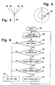
- Figure 4 illustrates an embodiment of the angular control limits for use with effecting such suppressing.
- the actual instantaneous direction of motion of the vehicle has been indicated by line 54.
- second range of larger changes in the orientation of the vehicle given by angle 52 which in this case is +/-45°.
- Figure 5 likewise illustrates an embodiment of the spatial control limits.
- the actual instantaneous direction of motion has again been indicated by line 54.
- the size of this circle may correspond to an average distance covered by the vehicle in 1 ⁇ 2 minute, such as 800 meters on a highway.
- the size of the circular window may even be controlled by the average vehicle speed during the last few minutes.
- there is a second range of larger changes in the position of the vehicle given by circle 58 which in this embodiment is twice as large as circle 56.
- Another possible shape for these windows may be square instead of circular.
- Figure 6 illustrates a first flow chart of the display control operation.
- the operation starts and necessary hardware and software facilities are assigned.
- the actual position and heading of the vehicle are determined.
- the system checks whether the vehicle is outside region 56 of Figure 5, as relative to the last time when such had been determined. Of course, initially the answer is No, whereupon the system goes to block 74, wherein the map display is only shifted so as to represent the changing position of the vehicle. If Yes, in block 68, the system determines whether the vehicle heading has only changed within small angle 50 in Figure 5. If No in block 68, the system in block 66 determines whether the vehicle has been in region 58 long enough, such as for longer than one minute. If Yes however, the system still goes to block 74.
- block 70 the system determines whether the vehicle has been within angle 52 long enough, such as for longer than one half minute. If No, the system still goes to block 74. If Yes, however, the system goes to block 72, wherein, next to the shifting of the map, also the rotating of the map will be in principle allowed. This will also set new boundaries for the windows regarding angles and position. After updating of the map display, the system will return to block 62 for executing a next turn of the loop. If necessary, a certain waiting time may be implemented for each turn of the loop.
- blocks 66 and 68 may be arranged in an OR-fashion, so that only one of the two need to give an output to the left for controlling a transition to block 72.
- the same may be valid for the two blocks 64 and 68, so that only one of the two need to give an "outside" answer for controlling a transition to the associated block 66, 70, respectively.
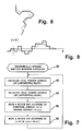
- Figure 7 illustrates another flow chart of the control operation.
- the abbreviation CCP means Current Car Positon indicator.
- the procedure Ergonomically optimum map/CCP movement and rotation is started.
- the local positional average of the route is calculated. In a more sophisticated embodiment, this will also include the anticipated route.
- the local heading average of the route is calculated. In a more sophisticated embodiment, this will also include the anticipated route. The anticipation may be extrapolated from actual position of the vehicle.
- Another implementation would include such anticipation on the basis on the planned route that has been presented to the driver on the basis of the driver's request for routeplanning and/or other data.
- the map is moved and rotated according to the positional average S and the heading average ⁇ (s), wherein s is the instantaneous position.
- the indicator CCP is moved and rotated according to the difference between the actual position s and positional average S , and also, according to the difference between the actual heading ⁇ (s) and the heading average ⁇ (s). Subsequently, the system returns to block 82.
- Figure 8 illustrates a diagram of a vehicle route subjected to an averaging operation. This usually implies that a more smooth curve (interrupted line) is derived from a route that is built up from often straight sections. Likewise,
- Figure 9 illustrates a diagram of the vehicle angular position subjected to an averaging operation. This may again imply that a smoother curve (interrupted line) is derived from a route which is built up from often straight sections.
Landscapes
- Engineering & Computer Science (AREA)
- Physics & Mathematics (AREA)
- Theoretical Computer Science (AREA)
- Mathematical Physics (AREA)
- Business, Economics & Management (AREA)
- Educational Administration (AREA)
- Educational Technology (AREA)
- General Physics & Mathematics (AREA)
- Navigation (AREA)
- Traffic Control Systems (AREA)
Abstract
Description
- The invention relates to a method for in an automotive vehicle displaying a road map that features an instantaneous signalization of the actual vehicle orientation and position whilst maintaining such orientation and position on a long term basis steady with respect to a display field. Various Vehicle Navigation Systems come with an arrangement for map display that will display various aspects of a planned route, such as a complete or partial road network in a region around the actual position of the vehicle, whilst highlighting therein the route that is to be followed according to the planning by the system. An elementary display system will display the map in a stationary manner, such as with North up. A more refined organisation therefor has a dynamic display, wherein the direction that is instantaneously followed by the vehicle will always be upward.
- The present inventor has experienced that in many normal driving conditions the latter approach will cause far too many rotations of the map. This will even apply when a certain averaging is effected of the instantaneous curves that are being followed. In a particular case of the vehicle following a route that is locally curved, but on the whole more or less straight, many ofthe rotations could just be superfluous and embarrassing to the driver. The above problem will likewise occur when just the route being followed is displayed, without a route planning feature being present or active.
- In consequence, amongst other things, it is an object of the present invention to restrict the amount and/or number of rotations in displaying such map to prevent embarrassing the driver and or detracting his attention from other incidents that could warrant immediate action.
- Now therefore, according to one of its aspects the invention is characterised by setting up a geographical window regarding actual movements of the vehicle, checking whether the vehicle remains inside or outside the window, if inside displaying said movements whilst at least partially suppressing such maintaining, and if outside displaying said movements whilst substantially upholding such maintaining. Such will allow for a more quiet display mode that will nevertheless present a user with adequate and easy-to- understand information regarding the vehicle position, and as such will improve the ergonomic performance of the display subsystem.
- In a preferred embodiment of the invention, the window has a first angular size. The inventor has recognised that small changes in the orientation or heading of the vehicle will cause little necessity for changing the display.
- In a further preferred embodiment of the invention, the window has a first smaller angular size wherein the maintaining of the orientation is fully suppressed, and a second larger angular size wherein maintaining of the orientation is temporarily attenuated. Such temporarily attenuating may imply a low-pass filtering of the changes, or generally, various operations to be executed in the time domain.
- Alternatively, the temporarily attenuating may imply a full suppressing of the angular change during a predetermined period of time, but thereafter allowing a filtered change of the map orientation.
- Advantageously, such window has a first linear size. The inventor has recognised that small movements in the position of the vehicle will cause little necessity for changing the display.
- Preferably, such window has a first smaller linear size wherein maintaining of the position is fully suppressed, and a second larger angular size wherein maintaining of the position is temporarily attenuated. Such temporarily attenuating may again imply a low-pass filtering of the changes, or generally, various operations to be executed in the time domain. Again, the temporarily attenuating may alternatively imply a full suppressing of the linear change during a predetermined period of time, but thereafter allowing a filtered change of the map position.
- In another preferred embodiment of the invention the method includes the step of determining long-term values for shift and rotation of the vehicle position with respect to a geography, effecting such maintaining with respect to such long-term values, whilst suppressing such maintaining with respect to discrepancies between actual vehicle position and orientation with respect to such long-term values. Whilst maintaining the essentials of the present invention as regarding both its objectives and the two types of maintaining versus suppressing of display rotation, this approach will under various circumstances produce a computationally and/or ergonomical superior solution.
- The invention also relates to a vehicle route display system arranged for implementing a method for in an automotive vehicle displaying a road map including actual vehicle orientation and position which on a long term basis are maintained steady and on a short time basis only selectively maintained under control of checking vehicle movements versus a window, and to a vehicle provided with such route display system. Further advantageous aspects of the invention are recited in the Claims.
- These and further aspects and advantages of the invention will be discussed more in detail hereinafter with reference to the disclosure of preferred embodiments, and in particular with reference to the appended Figures that show:
- Figure 1, a functional block diagram of a navigation system;
- Figure 2, a block diagram linking the navigation system to the map display;
- Figure 3, a detailed map display with travelling display of the vehicle position;
- Figure 4, an embodiment of the angular control limits;
- Figure 5, an embodiment of the spatial control limits;
- Figure 6, a flow chart of the control operation;
- Figure 7, another flow chart of the control operation;
- Figure 8, a diagram of a vehicle route subjected to an averaging operation;
- Figure 9, a diagram of the vehicle angular position subjected to an averaging operation.
-
- Figure 1 illustrates a functional block diagram of a vehicle navigation system.
Item 20 represents various absolute or relative position sensors, that may be based on roadside beacons, wheel sensors, GPS, or other. The input signals so received will allowsubsystem 24 to calculate an actual position and orientation of the vehicle.Block 22 has a map data base that is accessed bymicrocontroller 26 which also receives the actual vehicle position data fromsubsystem 24. - Through matching the position with the map, an on-map position with regard to a road will result, together with an actual direction of the vehicle in one of the two directions along that road. In principle, off-road positions are feasible, but such will be ignored hereinafter as not being fundamental to the present invention. Optionally,
block 26 may include a vehicle guidance organisation, through providing a calculated route to a destination, or including suggestions such as regarding instantaneous adversities connected with certain routes or parts thereof. The road map together with the instantaneous position of the vehicle will now be displayed ondisplay 28. - Figure 2 illustrates a block diagram linking the navigation system to the map display.
External data 20 will yield an actual position in block 24 (same numerals as in Figure 1).User request input 30 together with actual position will allow navigation control inblock 32 to calculate a target route. This will provide information to displaycontroller 34 that also receives actual position and orientation fromblock 24.Display field 36 is generally rectangular, although this is not a restriction, and displays the target route as anuninterrupted line 42, together with a representation of the instantaneous position and orientation of thevehicle 38. Generally, this will have some orientation signalization in the form of an arrow or the like. - Further relevant roads have been indicated in the form of
interrupted lines 40, but other types of relative highlighting of certain roads with respect to others are equally feasible. The whole system is arranged within a motor vehicle that has been succinctly indicated by thecomers 44 of a rectangle. - Now, prior art systems will display the vehicle position and orientation always in the same manner. Without express or implied limitation, the Figure has the orientation upward, and the position at some 40% from the bottom, but other values are feasible. It should be clear, in particular when considering Figure 3 hereinafter, that a fully maintaining steady of the vehicle representation could lead to many large and instantaneous jumps in the display, which could leave the viewer somewhat aghast. This could still apply when the vehicle motion were subjected to time-based filtering for suppressing high-frequency components thereof.
- Figure 3 illustrates a detailed map display with a travelling representation of the vehicle position, according to the target route displayed in Figure 2, but now maintaining the display field fully stationary. In this respect, the present inventor has recognised that doing such would on a small scale be acceptable, but on a large scale not at all. Moreover, there are two aspects of the maintaining: firstly, keeping the map position stationary, and secondly, keeping the map orientation stationary, but rather shifting the map position.
- The inventor has recognised that in many cases the map shifting is allowable under almost all circumstances, but maintaining the map orientation is not really necessary. In fact, in most cases the co-ordinates of the vehicle on the map scale would change quite slowly, whereas the orientation may readily change by 90° within a second. Accordingly, the preferred embodiment of the present invention is to let the map shift more or less exactly according to the position of the vehicle, whilst partially suppressing the rotations.
- Figure 4 illustrates an embodiment of the angular control limits for use with effecting such suppressing. The actual instantaneous direction of motion of the vehicle has been indicated by
line 54. There is a first range of small changes in the orientation of the vehicle given byangle 50, which in this case is +/-30°. Furthermore, there is a second range of larger changes in the orientation of the vehicle given byangle 52, which in this case is +/-45°. - Figure 5 likewise illustrates an embodiment of the spatial control limits. The actual instantaneous direction of motion has again been indicated by
line 54. There is a first range of small changes in the position of the vehicle given bycircle 56. The size of this circle may correspond to an average distance covered by the vehicle in ½ minute, such as 800 meters on a highway. The size of the circular window may even be controlled by the average vehicle speed during the last few minutes. Furthermore, there is a second range of larger changes in the position of the vehicle given bycircle 58, which in this embodiment is twice as large ascircle 56. Another possible shape for these windows may be square instead of circular. - Figure 6 illustrates a first flow chart of the display control operation. In
block 60, the operation starts and necessary hardware and software facilities are assigned. Inblock 62, the actual position and heading of the vehicle are determined. Inblock 64, the system checks whether the vehicle isoutside region 56 of Figure 5, as relative to the last time when such had been determined. Of course, initially the answer is No, whereupon the system goes to block 74, wherein the map display is only shifted so as to represent the changing position of the vehicle. If Yes, inblock 68, the system determines whether the vehicle heading has only changed withinsmall angle 50 in Figure 5. If No inblock 68, the system inblock 66 determines whether the vehicle has been inregion 58 long enough, such as for longer than one minute. If Yes however, the system still goes to block 74. If Yes, the system goes to block 70. Inblock 70, the system determines whether the vehicle has been withinangle 52 long enough, such as for longer than one half minute. If No, the system still goes to block 74. If Yes, however, the system goes to block 72, wherein, next to the shifting of the map, also the rotating of the map will be in principle allowed. This will also set new boundaries for the windows regarding angles and position. After updating of the map display, the system will return to block 62 for executing a next turn of the loop. If necessary, a certain waiting time may be implemented for each turn of the loop. - The logic of the decisions in Figure 6 may be amended to some extent. For example, blocks 66 and 68 may be arranged in an OR-fashion, so that only one of the two need to give an output to the left for controlling a transition to block 72. The same may be valid for the two
blocks block - The arrangement in Figure 6 has been simplified, such as by not showing terminating of the operation, such as when the vehicle power is shut off.
- Furthermore, the arrangement of Figure 6 has been set up with the understanding that an excess of the vehicle movement outside
angle 52 oroutside region 58 will immediately control a transition to block 72. - Figure 7 illustrates another flow chart of the control operation. Herein, the abbreviation CCP means Current Car Positon indicator. In
block 80, the procedure Ergonomically optimum map/CCP movement and rotation is started. Inblock 82, the local positional average of the route is calculated. In a more sophisticated embodiment, this will also include the anticipated route. Next, inblock 84, the local heading average of the route is calculated. In a more sophisticated embodiment, this will also include the anticipated route. The anticipation may be extrapolated from actual position of the vehicle. - Another implementation would include such anticipation on the basis on the planned route that has been presented to the driver on the basis of the driver's request for routeplanning and/or other data. Next, in
block 86, the map is moved and rotated according to the positional average S and the heading average Φ(s), wherein s is the instantaneous position. Finally, inblock 88, the indicator CCP is moved and rotated according to the difference between the actual position s and positional average S, and also, according to the difference between the actual heading ϕ(s) and the heading average Φ(s). Subsequently, the system returns to block 82. - Figure 8 illustrates a diagram of a vehicle route subjected to an averaging operation. This usually implies that a more smooth curve (interrupted line) is derived from a route that is built up from often straight sections. Likewise,
- Figure 9 illustrates a diagram of the vehicle angular position subjected to an averaging operation. This may again imply that a smoother curve (interrupted line) is derived from a route which is built up from often straight sections.
- Various further advantageous features of the invention and its embodiments would include the following.
- Long-term shifts and rotations of the vehicle position that have similar character, such as those that are more or less in the same direction, will be represented by moving the map, whereas differential shifts and rotations will be represented by moving the symbol used for the vehicle. This may be implemented by calculating a running average of position and orientation of the vehicle. The average is represented by the movements of the map. The discrepancy between actual values and average is represented by differences between the vehicle symbol position and orientation and the map representation.
- The intervals for determining the average position may be set, either by the user, or by the system. An example for the setting by the system may be relative to the size of the actual map which itself may depend on the type of route that is being followed and/or the remaining distance to the destination. The average may for example be 20% of the map height. The interval for calculating the average value may be based both on the route that will be followed, as well as on the route that has been followed already. If there is no planned route available, the averaging goes until the next route point where a splitting is present. In the above cases the route axis has developed to a fixed average curve.
- The map orientation may be changed smoothly or seamless. On the other hand, the rotation may be executed in a step-wise manner as well. In that case, the steps will be subjected to an upper bound. If a larger step were necessary, it will be executed in successive smaller steps that are separated in time, such as by a fixed time interval of e.g., 3 seconds. The result of the invention will generally be a quieter overall image, wherein the map will execute smooth motions, whereas the vehicle symbol will execute differential movements and rotations.
- A further advantage is to maintain the vehicle symbol always in a restricted region of the display, such as in the lower third of the display field, thereby keeping the main part of the map display in front of the vehicle.
- While the above described embodiments of the invention are the preferred ones, it is apparent to those skilled in the art that many other changes and modifications may be made, without departing from the invention in its broader aspects. Therefore the intentions of the claims is to cover such changes and modifications, falling within the true spirit and scope of the invention.
Claims (15)
- A method for in an automotive vehicle (44) displaying a road map that features an instantaneous signalization (38) of the actual vehicle orientation and position whilst maintaining such orientation and position on a long term basis steady with respect to a display field (36), characterised by setting up a geographical window (50, 52, 56, 58) regarding actual movements of the vehicle, checking (64, 66, 68, 70) whether the vehicle remains inside (1) or outside (2) the window, if inside displaying said movements whilst at least partially suppressing such maintaining, and if outside displaying said movements whilst substantially upholding such maintaining.
- A method as claimed in Claim 1, characterised in that such window has a first angular size (50).
- A method as claimed in Claim 2, characterised in that such window has a first smaller angular size (50) wherein such maintaining of the orientation is fully suppressed, and a second larger angular size (52) wherein maintaining of the orientation is temporarily attenuated.
- A method as claimed in Claim 1, characterised in that such window has a first linear size (56).
- A method as claimed in Claim 4, characterised in that such window has a first smaller linear size (56) wherein maintaining of the orientation is fully suppressed, and a second larger angular size (58) wherein maintaining of the orientation is temporarily attenuated.
- A method as claimed in Claim 1, characterised in that such window is set up regarding actual movements that include anticipated movements of the vehicle.
- A method for in an automotive vehicle (44) displaying a road map that features an instantaneous signalization (38) of the actual vehicle orientation and position whilst maintaining such orientation and position on a long term basis steady with respect to a display field (36), said method being characterised by the step of determining long-term values (82, 84) for shift and rotation of the vehicle position with respect to a geography, effecting such maintaining with respect to such long-term values (86), whilst suppressing such maintaining (88) with respect to discrepancies between actual vehicle position and orientation with respect to such long-term values.
- A method as claimed in Claim 7, characterised in that such long-term values are determined for an average position of the vehicle, and such average is determined for an interval in time or space that has an adjustable size.
- A method as claimed in Claim 8, characterised in that such interval includes a route that has been followed as well as a route that is intended to be followed by the vehicle.
- A method as claimed in Claim 9, characterised in that said route to be followed under absence of an active route planning feature is bounded at a next possible route splitting location.
- A method as claimed in Claims 1 or 7, characterised by a change in map orientation being effected in a smooth rotation.
- A method as claimed in Claims 1 or 7, characterised in that a change in map orientation is effected in a step, such step being restricted to an upper bound, and a larger change in map orientation is split into a sequence of time-spaced smaller steps that are each subject to such upper bound.
- An automotive vehicle route display system (34, 36) arranged for implementing a method as claimed in Claim 1, and having road map display means featuring an instantaneous signalization (38) of the actual vehicle orientation and position subject to maintaining means for maintaining such orientation and position on a long term basis steady with respect to a display field (36), being characterised by having geographical window set-up means for setting up a geographical window (50, 52, 56, 58) regarding actual movements of the vehicle, check means for checking (64, 66, 68, 70) whether the vehicle remains inside (1) or outside (2) the window, if inside outputting a suppress signal for at least partially suppressing such maintaining whilst displaying said movements, and if outside terminating such suppress signal for displaying said movements whilst substantially upholding such maintaining.
- An automotive vehicle route display system (34, 36) arranged for implementing a method as claimed in Claim 7, and having road map display means featuring an instantaneous signalization (38) of the actual vehicle orientation and position subject to maintaining means for maintaining such orientation and position on a long term basis steady with respect to a display field (36), being characterised by having determining means (82, 84) for determining long-term values for shift and rotation of the vehicle position with respect to a geography, and outputting a first control for effecting such maintaining (86) with respect to such long-term values, and a second control for suppressing such maintaining (88) with respect to discrepancies between actual vehicle position and orientation with respect to such long-term values.
- An automotive vehicle (44) provided with a route display system as claimed in Claims 13 or 14.
Priority Applications (2)
| Application Number | Priority Date | Filing Date | Title |
|---|---|---|---|
| EP01103318A EP1233392A1 (en) | 2001-02-13 | 2001-02-13 | A method for displaying a road map in an automotive vehicle |
| US10/073,351 US6643583B2 (en) | 2001-02-13 | 2002-02-13 | Method for displaying a road map in an automotive vehicle |
Applications Claiming Priority (1)
| Application Number | Priority Date | Filing Date | Title |
|---|---|---|---|
| EP01103318A EP1233392A1 (en) | 2001-02-13 | 2001-02-13 | A method for displaying a road map in an automotive vehicle |
Publications (1)
| Publication Number | Publication Date |
|---|---|
| EP1233392A1 true EP1233392A1 (en) | 2002-08-21 |
Family
ID=8176472
Family Applications (1)
| Application Number | Title | Priority Date | Filing Date |
|---|---|---|---|
| EP01103318A Ceased EP1233392A1 (en) | 2001-02-13 | 2001-02-13 | A method for displaying a road map in an automotive vehicle |
Country Status (2)
| Country | Link |
|---|---|
| US (1) | US6643583B2 (en) |
| EP (1) | EP1233392A1 (en) |
Families Citing this family (2)
| Publication number | Priority date | Publication date | Assignee | Title |
|---|---|---|---|---|
| JP3716801B2 (en) * | 2002-02-27 | 2005-11-16 | ヤマハ株式会社 | Vehicle position communication system and portable communication device |
| JP2008009915A (en) * | 2006-06-30 | 2008-01-17 | Pioneer Electronic Corp | Road sign determination apparatus, method and program |
Citations (3)
| Publication number | Priority date | Publication date | Assignee | Title |
|---|---|---|---|---|
| US5745866A (en) * | 1996-01-09 | 1998-04-28 | Trimble Navigation Limited | Cardinal-up graphic map display system |
| US5793310A (en) * | 1994-02-04 | 1998-08-11 | Nissan Motor Co., Ltd. | Portable or vehicular navigating apparatus and method capable of displaying bird's eye view |
| US5936631A (en) * | 1995-01-20 | 1999-08-10 | Mitsubishi Denki Kabushiki Kaisha | Mobile navigation system |
-
2001
- 2001-02-13 EP EP01103318A patent/EP1233392A1/en not_active Ceased
-
2002
- 2002-02-13 US US10/073,351 patent/US6643583B2/en not_active Expired - Lifetime
Patent Citations (3)
| Publication number | Priority date | Publication date | Assignee | Title |
|---|---|---|---|---|
| US5793310A (en) * | 1994-02-04 | 1998-08-11 | Nissan Motor Co., Ltd. | Portable or vehicular navigating apparatus and method capable of displaying bird's eye view |
| US5936631A (en) * | 1995-01-20 | 1999-08-10 | Mitsubishi Denki Kabushiki Kaisha | Mobile navigation system |
| US5745866A (en) * | 1996-01-09 | 1998-04-28 | Trimble Navigation Limited | Cardinal-up graphic map display system |
Also Published As
| Publication number | Publication date |
|---|---|
| US20020123842A1 (en) | 2002-09-05 |
| US6643583B2 (en) | 2003-11-04 |
Similar Documents
| Publication | Publication Date | Title |
|---|---|---|
| US5884217A (en) | Map display apparatus for motor vehicle | |
| EP1024467B1 (en) | Stereoscopic map-display method and navigation system using the method | |
| JP3508619B2 (en) | Vehicle navigation system | |
| US8095307B2 (en) | Method for controlling the display of a geographical map in a vehicle and display apparatus for that purpose | |
| US20040236507A1 (en) | Car navigation system | |
| US6157342A (en) | Navigation device | |
| JPH10143066A (en) | Map display method and device, and navigation device provided with the device | |
| US6591190B2 (en) | Navigation system | |
| WO2018100725A1 (en) | Autonomous driving control planning device and autonomous driving control planning method | |
| JP2000275057A (en) | Vehicle guidance device | |
| US20140358431A1 (en) | User Device and System | |
| CN115379975A (en) | Vehicle motion control device and vehicle motion control method | |
| JP2001167288A (en) | 3D map display device | |
| EP2546608B1 (en) | Map display system, method, and program | |
| JP3492887B2 (en) | 3D landscape map display method | |
| US6643583B2 (en) | Method for displaying a road map in an automotive vehicle | |
| JP2002538449A (en) | Navigation method and navigation apparatus for determining route from start point to destination point for transportation means | |
| KR102386312B1 (en) | Method and system for guiding tbt information using hd map and hud | |
| JP6206510B2 (en) | Map display system, method and program | |
| JP3476751B2 (en) | In-vehicle navigation device | |
| JP3841924B2 (en) | Navigation device | |
| CN101290231A (en) | Method for automatic switchover and map smoothly rotating between2.5 dimension and two-dimension in navigation procedure | |
| EP3845860A1 (en) | Image control program, image control device, and image control method | |
| JP2000161968A (en) | Map display method, map display device, and recording medium recording map display program | |
| JP2019215600A (en) | Map display system and map display program |
Legal Events
| Date | Code | Title | Description |
|---|---|---|---|
| PUAI | Public reference made under article 153(3) epc to a published international application that has entered the european phase |
Free format text: ORIGINAL CODE: 0009012 |
|
| AK | Designated contracting states |
Kind code of ref document: A1 Designated state(s): AT BE CH CY DE DK ES FI FR GB GR IE IT LI LU MC NL PT SE TR |
|
| AX | Request for extension of the european patent |
Free format text: AL;LT;LV;MK;RO;SI |
|
| 17P | Request for examination filed |
Effective date: 20020905 |
|
| AKX | Designation fees paid |
Designated state(s): DE FR GB IT |
|
| 17Q | First examination report despatched |
Effective date: 20060309 |
|
| RAP1 | Party data changed (applicant data changed or rights of an application transferred) |
Owner name: CONTINENTAL AUTOMOTIVE GMBH |
|
| STAA | Information on the status of an ep patent application or granted ep patent |
Free format text: STATUS: THE APPLICATION HAS BEEN REFUSED |
|
| 18R | Application refused |
Effective date: 20130915 |