EP1233240A2 - Absorption type cooling and heating apparatus - Google Patents
Absorption type cooling and heating apparatus Download PDFInfo
- Publication number
- EP1233240A2 EP1233240A2 EP02003108A EP02003108A EP1233240A2 EP 1233240 A2 EP1233240 A2 EP 1233240A2 EP 02003108 A EP02003108 A EP 02003108A EP 02003108 A EP02003108 A EP 02003108A EP 1233240 A2 EP1233240 A2 EP 1233240A2
- Authority
- EP
- European Patent Office
- Prior art keywords
- conduit
- refrigerant
- condenser
- regenerator
- absorber
- Prior art date
- Legal status (The legal status is an assumption and is not a legal conclusion. Google has not performed a legal analysis and makes no representation as to the accuracy of the status listed.)
- Granted
Links
Images

Classifications
-
- F—MECHANICAL ENGINEERING; LIGHTING; HEATING; WEAPONS; BLASTING
- F25—REFRIGERATION OR COOLING; COMBINED HEATING AND REFRIGERATION SYSTEMS; HEAT PUMP SYSTEMS; MANUFACTURE OR STORAGE OF ICE; LIQUEFACTION SOLIDIFICATION OF GASES
- F25B—REFRIGERATION MACHINES, PLANTS OR SYSTEMS; COMBINED HEATING AND REFRIGERATION SYSTEMS; HEAT PUMP SYSTEMS
- F25B15/00—Sorption machines, plants or systems, operating continuously, e.g. absorption type
- F25B15/02—Sorption machines, plants or systems, operating continuously, e.g. absorption type without inert gas
-
- F—MECHANICAL ENGINEERING; LIGHTING; HEATING; WEAPONS; BLASTING
- F25—REFRIGERATION OR COOLING; COMBINED HEATING AND REFRIGERATION SYSTEMS; HEAT PUMP SYSTEMS; MANUFACTURE OR STORAGE OF ICE; LIQUEFACTION SOLIDIFICATION OF GASES
- F25B—REFRIGERATION MACHINES, PLANTS OR SYSTEMS; COMBINED HEATING AND REFRIGERATION SYSTEMS; HEAT PUMP SYSTEMS
- F25B15/00—Sorption machines, plants or systems, operating continuously, e.g. absorption type
-
- F—MECHANICAL ENGINEERING; LIGHTING; HEATING; WEAPONS; BLASTING
- F25—REFRIGERATION OR COOLING; COMBINED HEATING AND REFRIGERATION SYSTEMS; HEAT PUMP SYSTEMS; MANUFACTURE OR STORAGE OF ICE; LIQUEFACTION SOLIDIFICATION OF GASES
- F25B—REFRIGERATION MACHINES, PLANTS OR SYSTEMS; COMBINED HEATING AND REFRIGERATION SYSTEMS; HEAT PUMP SYSTEMS
- F25B29/00—Combined heating and refrigeration systems, e.g. operating alternately or simultaneously
- F25B29/006—Combined heating and refrigeration systems, e.g. operating alternately or simultaneously of the sorption type system
-
- F—MECHANICAL ENGINEERING; LIGHTING; HEATING; WEAPONS; BLASTING
- F25—REFRIGERATION OR COOLING; COMBINED HEATING AND REFRIGERATION SYSTEMS; HEAT PUMP SYSTEMS; MANUFACTURE OR STORAGE OF ICE; LIQUEFACTION SOLIDIFICATION OF GASES
- F25B—REFRIGERATION MACHINES, PLANTS OR SYSTEMS; COMBINED HEATING AND REFRIGERATION SYSTEMS; HEAT PUMP SYSTEMS
- F25B41/00—Fluid-circulation arrangements
- F25B41/20—Disposition of valves, e.g. of on-off valves or flow control valves
- F25B41/28—Disposition of valves, e.g. of on-off valves or flow control valves specially adapted for sorption cycles
-
- Y—GENERAL TAGGING OF NEW TECHNOLOGICAL DEVELOPMENTS; GENERAL TAGGING OF CROSS-SECTIONAL TECHNOLOGIES SPANNING OVER SEVERAL SECTIONS OF THE IPC; TECHNICAL SUBJECTS COVERED BY FORMER USPC CROSS-REFERENCE ART COLLECTIONS [XRACs] AND DIGESTS
- Y02—TECHNOLOGIES OR APPLICATIONS FOR MITIGATION OR ADAPTATION AGAINST CLIMATE CHANGE
- Y02A—TECHNOLOGIES FOR ADAPTATION TO CLIMATE CHANGE
- Y02A30/00—Adapting or protecting infrastructure or their operation
- Y02A30/27—Relating to heating, ventilation or air conditioning [HVAC] technologies
-
- Y—GENERAL TAGGING OF NEW TECHNOLOGICAL DEVELOPMENTS; GENERAL TAGGING OF CROSS-SECTIONAL TECHNOLOGIES SPANNING OVER SEVERAL SECTIONS OF THE IPC; TECHNICAL SUBJECTS COVERED BY FORMER USPC CROSS-REFERENCE ART COLLECTIONS [XRACs] AND DIGESTS
- Y02—TECHNOLOGIES OR APPLICATIONS FOR MITIGATION OR ADAPTATION AGAINST CLIMATE CHANGE
- Y02B—CLIMATE CHANGE MITIGATION TECHNOLOGIES RELATED TO BUILDINGS, e.g. HOUSING, HOUSE APPLIANCES OR RELATED END-USER APPLICATIONS
- Y02B30/00—Energy efficient heating, ventilation or air conditioning [HVAC]
- Y02B30/62—Absorption based systems
Definitions
- the present invention relates to an absorption type cooling and heating apparatus for operating in three different modes: cooling operation, heat-pump heating operation, and direct-burner or direct flame heating operation, and particularly to an absorption type cooling and heating apparatus arranged in which a cooling operation and a heat-pump operation are carried out at optimum conditions and can readily be switched to a direct-burner heating operation.
- the absorption type cooling and heating apparatus with the dedicated circulation path however needs an extra conduit of the dedicated circulation path for circulating the refrigerant, hence increasing the number of joints. This is unfavorable for generating a degree of vacuum in the system of the apparatus.
- the apparatus may be modified with a bypass where the refrigerant over-flown from the condenser is directly returned back to the top portion of the rectifier. It is yet necessary for inhibiting overflow in the other operation mode than the direct-burner heating operation to save a more amount of the refrigerant in the condenser. As a result, the duration of time from the initiation of the direct-burner heating operation to the start of overflow will be extended thus creating substantially a time delay be fore starting the direct-burner heating operation. As the refrigerant remaining in the condenser stays out of the actual operation, the energy spent for saving the refrigerant prior to the overflow will be wasted.
- the refrigerant remains at a considerable amount in the condenser at the start-up and will not move into the evaporator before a substantial difference in the pressure is developed. Therefore, the solution circulated from the absorber to the regenerator becomes highly dense and its density may be too high in the regenerator. This results in a less-vapor state in the regenerator. It is hence needed for preparing an excess amount of the refrigerant in the evaporator at the start-up to feed a redundancy of the refrigerant into the evaporator.
- Present invention having the first feature comprising an evaporator for holding a refrigerant, an absorber for allowing an absorbent solution to absorb a refrigerant vapor generated in the evaporator, a regenerator for recovering the density of an absorbent in the absorbent solution by heating up to extract the refrigerant vapor from the absorbent solution, a refrigerant vapor passage for transferring the refrigerant vapor from the regenerator to a condenser, and the condenser for condensing the refrigerant vapor which is returned back to the evaporator, where in a cooling operation, a heat-pump heating operation, and a direct-burner heating operation can be performed selectively, said absorption type cooling and heating apparatus comprising, a first conduit for transferring the condensed refrigerant generated in the condenser to the evaporator, a second conduit for transferring the absorbent solution from the absorber to the regenerator, a branch conduit branched from the first conduit, and a switching device for
- the communication between the branch conduit and the second conduit by the action of the switching device allows the refrigerant to flow from the condenser via the branch conduit and the second conduit to the regenerator.
- the branch conduit and the second conduit are disconnected from each, the refrigerant is transferred via the first conduit to the evaporator.
- the switching device is a first check valve for allowing the flow from the condenser via the branch conduit to the regenerator while a second check valve is also provided for allowing the flow from the absorber to the regenerator, the first and second check valve communicated with each other at the downstream side.
- the second check valve is closed to inhibit the flow of the solution from the absorber to the regenerator.
- the first check valve is closed to inhibit the flow of the refrigerant from the condenser to the regenerator.
- Present invention having the third feature in which the first and second check valves are assembled in a single unit having a movable valve portion provided at the downstream junction thereof so that the valve portion can be shifted to each end of its movement by a pressure difference between two fluids introduced into the input ports of the first and second check valves, thus the first check valve is shut up when the valve portion shifted to one end of its movement and the second check valve when the valve portion shifted to the other end.
- the first and second check valves are assembled together with the single valve provided for common use, hence contributing to the simplification of the overall arrangement. Also, the first and second check valves are selectively operated with the valve shifted for opening by the action of a pressure difference between two fluid inputs. As a result, no actuator will be needed for driving the valve.
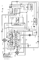
- Fig. 1 is a block diagram showing a primary part of an absorption cooling and heating apparatus of the embodiment of the present invention.
- An evaporator 1 accommodates a refrigerant of fluoride alcohol, such as trifluoroethanol (TFE), while an absorber 2 accommodates a solution of DMI derivative, such as dimethyl-imidazolidinon, which contains an absorbent.
- the refrigerant is not limited to fluoride alcohol but may be an appropriate agent of which the nonfreezing range is wide.
- the solution is not limited either to the DMI derivative and it may be any other absorbent solution which is wide in the nonfreezing range, being higher than TFE in atmospheric temperature boiling point and having an enough power to absorb TFE.
- the evaporator 1 and the absorber 2 are fluidly communicated to each other by a (refrigerant) vapor passage.
- a (refrigerant) vapor passage When the evaporator 1 is kept under a low pressure condition of e.g. 30 mmHg, the refrigerant is vaporized therein and moves via the passage into the absorber 2, as denoted by the double-line arrows. The refrigerant vapor is then absorbed by the absorbent in the absorber 2 thus causing an absorption freezing action.
- Absorption refrigerating action is implemented by absorbing the vapor refrigerant with the solution in the absorber 2.
- a cooler (heat exchanger) 18 is provided in the vapor passage.
- a tube or pipe 1a for passing a cooled water is mounted to run through the evaporator 1 by using a pump P4.
- the tube 1a is connected at one end (the exit side in the embodiment shown) to the No.1 opening of a first four-way valve V1 and at the other end (the entrance side in the embodiment) to the No.1 opening of a second four-way valve V2.
- the refrigerant is fed by the action of a pump P1 to a spraying means 1b mounted in the evaporator 1 for being sprayed over the tube 1a in which the cooled water runs.
- the refrigerant deprives the cooled water in the tube 1a of heat and turns to a refrigerant vapor which passes via the cooler 18 on the vapor passage into the absorber 2. Consequently, the temperature of the cooled water is more declined.
- the refrigerant in the evaporator 1 is driven by the pump P1 to the spraying means and, its portion is passed through the filter 4 and transferred to the substantial top portion of the rectifier 6.
- a flow control valve V5 is provided on a conduit 1c as a bleed line located between the evaporator 1 and the filter 4.
- the cooled water running in the tube 1a may preferably be either an ethylene glycol or propylene glycol water solution.
- a tube 2a is provided in the absorber 2 for passing a flow of cooling water.
- the tube 2a is connected at one end (the exit side in the embodiment shown) via a condenser 9 and a pump P3 to the No.2 opening of the first four-way valve V1 and at the other end (the entrance side) to the No.2 opening of the second four-way valve V2.
- the cooling water running along the tube 2a is the same as the cooled water which runs across the tube 1a in properties or constitution.
- the absorbent solution is fed by the action of the pump P2 to a spraying means 2b mounted in the absorber 2 for being sprayed over the tube 2a. Consequently, the solution is cooled down by the cooling water running along the tube 2a. Simultaneously, the cooling water deprives the solution of heat and its temperature will increase. As the solution in the absorber 2 has absorbed the refrigerant vapor, the concentration of the absorbent drops thus lowering the absorbing capability of the solution.
- the diluted solution which has absorbed the refrigerant vapor in the absorber 2 is passed via a tube 7b and a control valve or second check valve V3 to the rectifier 6 and the regenerator 3 by the pump P2.
- the regenerator 3 is provided with the burner 7 for heating up the diluted solution.
- the burner 7 may be a gas burner or any other heating means.
- the solution is heated by the burner 7 and the concentration of the absorbent is increased as the refrigerant vapor is separated.
- the resultant (concentrated) solution is returned via a tube 7a and a control valve V4 to the absorber 2 where it is sprayed over the tube 2a by the spraying means 2b and pump P2.
- the refrigerant vapor generated in the regenerator 3 transferred to the condenser after sufficient separation of a small amount of mixed absorbent solution component from the absorbent solution which is flow down in the rectifier 6 by sufficient contact of the vapor when the vapor flow upward in the rectifier 6.
- the refrigerant which is cooled and condensed in the condenser 9 is fed back to the evaporator 1 by passing through the conduit 9b via the cooler 18 and depression valve (flow control valve) 11, then is sprayed on the conduit 1a by spray means.
- the cooler 18 which is a heat exchanger composed on the vapor passage.
- the cooler 18 accelerate vaporization of the mixed refrigerant mist in the refrigerant vapor generated in the evaporator 1 by heat up the warm refrigerant which is fed back from the condenser. Simultaneously, it depresses the temperature of the refrigerant fed back to the evaporator 1.
- the conduit 9b by which the refrigerant is fed back from the condenser 9 to the evaporator 1, is branched into the conduit 9a which is j join with the conduit 7b at downstream side of the check valve V3.
- the branch conduit 9a is provided of a check valve (first check valve) 17 which allows the refrigerant flow into the conduit 7b from the condenser 9.
- the conduit 9a provides a portion of a circulation pass in which the refrigerant is fed back to the regenerator 3 from the condenser 9 during the direct burner heating operation.
- the concentration of the refrigerant circulated from the condenser 9 to the evaporator 1 is very high, it may inevitably be declined with a small amount of the absorbent accumulated therein through long operation cycles in the evaporator 1.
- a portion of the refrigerant from the evaporator 1 is transferred via the filter 4 to the rectifier 6 as described above.
- the filtering action of the filter 4 inhibits any dirt or rust in the refrigerant from blocking up the conduits in the rectifier 6 and decreasing their function.
- the high-temperature strong solution received from the conduit 7a of the regenerator 3 is subjected to a heat exchanging action with the weak solution received from the conduit 7 of the absorber and its resultant cooled down solution is transferred and sprayed in the absorber 2.
- the weak solution heated up preliminary in the heat exchanger 12 is transferred to the rectifier 6.
- another heat exchanger (not shown) may be provided for transmitting the heat from the strong solution to the cooling water in the conduit 2a connected from the absorber 2 or the condenser 9. As the temperature of the cooling water is increased, the temperature of the strong solution flowed to the absorber 2 will drop down more.
- a sensible heat exchanger 14 for exchanging heat of the cooled water or cooling water with the ambient air is linked to a conduit 4a while a room unit 15 is lined to a conduit 3a.
- the two conduits 3a and 4a (the inlets as illustrated) are connected at one end to the ports #3 and #4 of the first four-way valve V1 respectively and at the other end (the outlets as illustrated) to the ports #3 and #4 of the second four-way valve V2 respectively.
- the room unit 15 has a fan 10 and its blow outlet (not shown) provided for common use to releasing blows of cooling air and warming air and is located in a room to be cooled or heated.
- the sensitive heat exchanger 14 is located at the outdoor for forcibly exchanging heat with the ambient air using a fan 19.
- T1, T3, T9, T14, and T15 are temperature sensors, by L1, L2, and L9 are liquid level sensors, and by PS1 and PS9 are pressure sensors.
- the first four-way valve V1 are controlled so as to connect the ports #1 and #4 and, the second four-way valve V2 are controlled so as to connect the ports #2 and #3. This allows the cooling water heated in the absorber 2 and the condenser 9 and received from the conduit 2a to be conveyed by the action of the pump P3 to the conduit 3a in the room unit 15 for heating the room.
- the heating capability will be declined when the ambient temperature is extremely low and its heat is hardly taken in.
- the heat-pump heating operation is switched to the direct-burner heating operation where the refrigerant vapor generated in the regenerator 3 is transferred to and from the condenser 9.
- the energy of heat by the burner 7 is efficiently transferred by the action of the condenser 9 to the cooling water running in the conduit 2a in the direct-burner heating operation, the temperature of the cooling water is raised and the heating capability can be increased.
- both the conduit 9b of the refrigerant from the condenser 9 to the evaporator 1 and the conduit 7a of the strong solution from the regenerator 3 to the absorber 2 are shut up to suspend the heat-pump heating operation.
- the refrigerant condensed in the condenser 9 is returned back to the regenerator 3 via the conduits 9b, 9a, and 7b by the action of check valves 17 and V3 which will be explained later in more detail.
- the switching from the heat-pump heating operation to the direct-burner heating operation may automatically be implemented according to the temperature detected by the temperature sensor T14 provided at an appropriate location at the outdoor (for example, adjacent to the sensitive heat exchanger 14) upon sensing that the ambient temperature drops down to below a predetermined level. Lower ambient temperature below the predetermined level may be determined from whether the load in the heating becomes too high or not.
- the calculation of the load in the heating operation and the switching to the direct-burner heating operation are depicted in Japanese Patent Laid-open Publications (Heisei) 6-318183 and 10-185344 by us, the applicants, which are quoted as the references in this application.
- Figs. 2A and 2B are cross sectional views of a three-way valve implemented by a combination of the two check valves V3 and 17.
- Fig. 2A illustrates the heat-pump heating operation while
- Fig. 2B illustrates the direct-burner heating operation or full condensation and start-up of the operation. It is assumed that, during the heat-pump heating operation shown in Fig. 2A, the pressure PS1 exerted at the condenser 9 side of the check valve 17 is 350 Torr. Similarly, the pressure PS2 exerted at the absorber 2 side of the check valve V3 is 450 Torr.
- the pressure PS2 includes a partial pressure derived from the heat exchanger 12, it is higher than the pressure PS1.
- the check valve 17 is closed to cancel the transfer of the refrigerant from the condenser 9 to the regenerator 3.
- the pressure PS2 at the upstream of the check valve V3 is about 20 Torr as is much smaller than the pressure PS1 (about 350 Torr) at the condenser 9 side of the check valve 17.
- the pressure PS2 is substantially close to the saturated pressure at either the absorber 2 or the evaporator 1.
- the check valve V3 is closed to inhibit the flow of the weak solution from the absorber 2 to the regenerator 3.
- the check valve 17 is opened to permit the flow of the refrigerant from the condenser 9 to the regenerator 3.
- the refrigerant from the condenser 9 is delivered via the conduits 9a and 7b to the regenerator 3.
- the conduit 9a is closed to transfer the refrigerant from the condenser 9 to the evaporator 1.
- the heat-pump heating operation is transferred to the direct-burner heating operation, the refrigerant is delivered from the condenser 9 via the conduits 9a and 7b to the regenerator 3.
- the circulation passes for the refrigerant and the absorbent solution can successfully be developed to implement each of the operation modes as the branch conduit 9a has automatically been switched by the effect of a difference in the pressure between the condenser 9 side and the absorber 2 side.
- Figs. 3A and 3B are cross sectional view of a modifications having a single moving part or valve provided for switching between the conduits.
- Fig. 3A illustrates the heat-pump heating operation while Fig. 3B illustrates the direct-burner heating operation which runs at the full condensation mode or the start-up mode.
- a valve assembly 21 has a free ball 22 provided therein as the valve (the moving part) for free movement in the valve assembly 21. When the ball 22 is shifted to the left as shown in Fig.
- the pressure PS2 at the absorber 2 side is higher than the pressure PS1 at the condenser 9 side in the heat-pump heating operation thus shifting the ball 22 to shut up the port 21a.
- This movement allows the weak solution to flow from the absorber 2 into the regenerator 3 and inhibits the refrigerant from receiving via the branch conduit 9a from the condenser 9.
- the pressure PS2 at the absorber 2 side becomes lower than the pressure PS1 at the condenser 9 side thus shifting the ball 22 to shut up the port 21b. This inhibits the weak solution from receiving from the absorber 2 and allows the refrigerant to flow from the condenser 9 via the branch conduit 9a into the regenerator 3.
- the second check valve is closed to inhibit the flow of the solution from the absorber to the regenerator when the start-up operation or the directly-burner heating operation is initiated, i.e. the pressure is lower at the absorber side than at the condenser side.
- the first check valve is closed to inhibit the flow of the refrigerant from the condenser to the regenerator.
- valve is shifted by the action of a pressure difference in the system thus to switch the flow from one conduit to another. Accordingly, the overall arrangement can be simplified with the use of no valve actuator.
- the refrigerant is conveyed from the condenser to the regenerator by the action of the switching means but not over-flown from the condenser, the following advantage is gained. Since the solution to be processed is greater in the amount than the rectifying step in the direct-burner heating operation, its over-flow will increase. If the size of the rectifier is determined in view of the over-flow, it may hardly conform to the requirement of the rectifying action.
- the present invention allows the rectifier to be sized in view of only optimization of its rectifying function.
- the refrigerator needs not to stay in the condenser until it over-flows, its overall amount in the system can be minimized and the condenser can be downsized. It is also unnecessary to support the energy until the over-flow starts.
Landscapes
- Engineering & Computer Science (AREA)
- Physics & Mathematics (AREA)
- Mechanical Engineering (AREA)
- Thermal Sciences (AREA)
- General Engineering & Computer Science (AREA)
- Sorption Type Refrigeration Machines (AREA)
Abstract
Description
- The present invention relates to an absorption type cooling and heating apparatus for operating in three different modes: cooling operation, heat-pump heating operation, and direct-burner or direct flame heating operation, and particularly to an absorption type cooling and heating apparatus arranged in which a cooling operation and a heat-pump operation are carried out at optimum conditions and can readily be switched to a direct-burner heating operation.
- There has been increased the demand of an absorption type cooling and heating apparatus which can carry out a heat-pump heating operation with the use of heat pumped up by an absorber in addition to a cooling operation. Such a heat-pump heating may however be declined in the efficiency of pumping up an energy of heat as the ambient temperature drops down. For compensation, an improvement is disclosed in Japanese Patent Publication (Heisei)6-97127 where if the ambient temperature is too low, the heat-pump heating operation is replaced with a direct-burner heating operation.
- We, the applicants, have developed an absorption type cooling and heating apparatus which can easily switch between a cooling operation, a heat-pump heating operation, and a direct-burner heating operation as is disclosed in Japanese Patent Laid-open Publication (Heisei)10-197008. Our reference cooling and heating apparatus has a closed circulation loop where, when heat-pump heating operation fails to generate a required power of heating, a refrigerant in vapor heated to a high temperature by a regenerator is transferred to a condenser where it comes into contact with a contact with a cooling water conduit and is thus condensed before returned back to the regenerator. This allows the refrigerant vapor extracted from the regenerator to be fully condensed by the condenser but not circulated from the condenser to an evaporator, thus shifting from the heat-pump heating operation to the direct-burner heating operation.
- Also, we have developed another absorption type cooling and heating apparatus which has a dedicated circulation path for permitting the refrigerant to spontaneously drop down from a condenser to a rectifier thus to circulate from the condenser via the rectifier to a regenerator as disclosed in Japanese Patent Laid-open Publication (Heisei)10-267448.
- The absorption type cooling and heating apparatus with the dedicated circulation path however needs an extra conduit of the dedicated circulation path for circulating the refrigerant, hence increasing the number of joints. This is unfavorable for generating a degree of vacuum in the system of the apparatus. The apparatus may be modified with a bypass where the refrigerant over-flown from the condenser is directly returned back to the top portion of the rectifier. It is yet necessary for inhibiting overflow in the other operation mode than the direct-burner heating operation to save a more amount of the refrigerant in the condenser. As a result, the duration of time from the initiation of the direct-burner heating operation to the start of overflow will be extended thus creating substantially a time delay be fore starting the direct-burner heating operation. As the refrigerant remaining in the condenser stays out of the actual operation, the energy spent for saving the refrigerant prior to the overflow will be wasted.
- Also, the refrigerant remains at a considerable amount in the condenser at the start-up and will not move into the evaporator before a substantial difference in the pressure is developed. Therefore, the solution circulated from the absorber to the regenerator becomes highly dense and its density may be too high in the regenerator. This results in a less-vapor state in the regenerator. It is hence needed for preparing an excess amount of the refrigerant in the evaporator at the start-up to feed a redundancy of the refrigerant into the evaporator.
- It is an object of the present invention to provide an absorption type cooling and heating apparatus which carries out a cooling operation or a heat-pump heating operation at optimum conditions and when needed, readily switch the operation mode into a direct-burner heating operation while eliminating the foregoing drawbacks.
- Present invention having the first feature comprising an evaporator for holding a refrigerant, an absorber for allowing an absorbent solution to absorb a refrigerant vapor generated in the evaporator, a regenerator for recovering the density of an absorbent in the absorbent solution by heating up to extract the refrigerant vapor from the absorbent solution, a refrigerant vapor passage for transferring the refrigerant vapor from the regenerator to a condenser, and the condenser for condensing the refrigerant vapor which is returned back to the evaporator, where in a cooling operation, a heat-pump heating operation, and a direct-burner heating operation can be performed selectively, said absorption type cooling and heating apparatus comprising, a first conduit for transferring the condensed refrigerant generated in the condenser to the evaporator, a second conduit for transferring the absorbent solution from the absorber to the regenerator, a branch conduit branched from the first conduit, and a switching device for selectively communicating the branch conduit to the second conduit.
- According to the first feature of the present invention, the communication between the branch conduit and the second conduit by the action of the switching device allows the refrigerant to flow from the condenser via the branch conduit and the second conduit to the regenerator. When the branch conduit and the second conduit are disconnected from each, the refrigerant is transferred via the first conduit to the evaporator.
- Present invention having the second feature in which the switching device is a first check valve for allowing the flow from the condenser via the branch conduit to the regenerator while a second check valve is also provided for allowing the flow from the absorber to the regenerator, the first and second check valve communicated with each other at the downstream side.
- According to the second feature of the present invention, at the start-up mode or the direct-burner heating operation mode where the pressure is lower at the absorber side than at the condenser side, the second check valve is closed to inhibit the flow of the solution from the absorber to the regenerator. On the other hand, at the heat-pump heating operation mode where the pressure is higher at the absorber side than at the condenser side, the first check valve is closed to inhibit the flow of the refrigerant from the condenser to the regenerator.
- Present invention having the third feature in which the first and second check valves are assembled in a single unit having a movable valve portion provided at the downstream junction thereof so that the valve portion can be shifted to each end of its movement by a pressure difference between two fluids introduced into the input ports of the first and second check valves, thus the first check valve is shut up when the valve portion shifted to one end of its movement and the second check valve when the valve portion shifted to the other end.
- According to the third feature of the present invention, the first and second check valves are assembled together with the single valve provided for common use, hence contributing to the simplification of the overall arrangement. Also, the first and second check valves are selectively operated with the valve shifted for opening by the action of a pressure difference between two fluid inputs. As a result, no actuator will be needed for driving the valve.
-
- Fig. 1 is a schematic view of a cooling and heating apparatus showing one embodiment of the present invention;
- Figs. 2A and 2B are a cross sectional view of a check valve mounted across a conduit for circulating a refrigerant from a condenser to a regenerator; and
- Figs. 3A and 3B are a cross sectional view showing a modification of the check valve.
-
- A preferred embodiment of the present invention will be described in more detail referring to the accompanying drawings. Fig. 1 is a block diagram showing a primary part of an absorption cooling and heating apparatus of the embodiment of the present invention. An
evaporator 1 accommodates a refrigerant of fluoride alcohol, such as trifluoroethanol (TFE), while anabsorber 2 accommodates a solution of DMI derivative, such as dimethyl-imidazolidinon, which contains an absorbent. The refrigerant is not limited to fluoride alcohol but may be an appropriate agent of which the nonfreezing range is wide. The solution is not limited either to the DMI derivative and it may be any other absorbent solution which is wide in the nonfreezing range, being higher than TFE in atmospheric temperature boiling point and having an enough power to absorb TFE. - The
evaporator 1 and theabsorber 2 are fluidly communicated to each other by a (refrigerant) vapor passage. When theevaporator 1 is kept under a low pressure condition of e.g. 30 mmHg, the refrigerant is vaporized therein and moves via the passage into theabsorber 2, as denoted by the double-line arrows. The refrigerant vapor is then absorbed by the absorbent in theabsorber 2 thus causing an absorption freezing action. - Absorption refrigerating action is implemented by absorbing the vapor refrigerant with the solution in the
absorber 2. A cooler (heat exchanger) 18 is provided in the vapor passage. - When a
burner 7 is lit to heat up aregenerator 3 for increasing the concentration of the absorbent solution in theabsorber 2, the absorbent absorbs the refrigerant vapor in theabsorber 2 and the evaporation of the refrigerant in theevaporator 1 is accelerated hence cooling down the interior of theevaporator 1 with the latent heat of the refrigerant evaporation. The burner, the regenerator, and the concentration of the absorbent solution will be described later in more detail. A tube or pipe 1a for passing a cooled water is mounted to run through theevaporator 1 by using a pump P4. The tube 1a is connected at one end (the exit side in the embodiment shown) to the No.1 opening of a first four-way valve V1 and at the other end (the entrance side in the embodiment) to the No.1 opening of a second four-way valve V2. The refrigerant is fed by the action of a pump P1 to a spraying means 1b mounted in theevaporator 1 for being sprayed over the tube 1a in which the cooled water runs. The refrigerant deprives the cooled water in the tube 1a of heat and turns to a refrigerant vapor which passes via thecooler 18 on the vapor passage into theabsorber 2. Consequently, the temperature of the cooled water is more declined. - The refrigerant in the
evaporator 1 is driven by the pump P1 to the spraying means and, its portion is passed through thefilter 4 and transferred to the substantial top portion of the rectifier 6. A flow control valve V5 is provided on a conduit 1c as a bleed line located between theevaporator 1 and thefilter 4. The cooled water running in the tube 1a may preferably be either an ethylene glycol or propylene glycol water solution. - As the refrigerant vapor is absorbed by the solution in the
absorber 2, the absorption heat increases the temperature of the solution. The lower the temperature and the higher the concentration of the solution, the greater the absorbing capability of the solution will be. For attenuating the temperature increase of the solution, a tube 2a is provided in theabsorber 2 for passing a flow of cooling water. The tube 2a is connected at one end (the exit side in the embodiment shown) via acondenser 9 and a pump P3 to the No.2 opening of the first four-way valve V1 and at the other end (the entrance side) to the No.2 opening of the second four-way valve V2. Preferably, the cooling water running along the tube 2a is the same as the cooled water which runs across the tube 1a in properties or constitution. - The absorbent solution is fed by the action of the pump P2 to a spraying means 2b mounted in the
absorber 2 for being sprayed over the tube 2a. Consequently, the solution is cooled down by the cooling water running along the tube 2a. Simultaneously, the cooling water deprives the solution of heat and its temperature will increase. As the solution in theabsorber 2 has absorbed the refrigerant vapor, the concentration of the absorbent drops thus lowering the absorbing capability of the solution. - The diluted solution which has absorbed the refrigerant vapor in the
absorber 2 is passed via atube 7b and a control valve or second check valve V3 to the rectifier 6 and theregenerator 3 by the pump P2. Theregenerator 3 is provided with theburner 7 for heating up the diluted solution. Theburner 7 may be a gas burner or any other heating means. The solution is heated by theburner 7 and the concentration of the absorbent is increased as the refrigerant vapor is separated. The resultant (concentrated) solution is returned via a tube 7a and a control valve V4 to theabsorber 2 where it is sprayed over the tube 2a by the spraying means 2b and pump P2. - The refrigerant vapor generated in the
regenerator 3 transferred to the condenser after sufficient separation of a small amount of mixed absorbent solution component from the absorbent solution which is flow down in the rectifier 6 by sufficient contact of the vapor when the vapor flow upward in the rectifier 6. The refrigerant which is cooled and condensed in thecondenser 9 is fed back to theevaporator 1 by passing through the conduit 9b via the cooler 18 and depression valve (flow control valve) 11, then is sprayed on the conduit 1a by spray means. The cooler 18 which is a heat exchanger composed on the vapor passage. The cooler 18 accelerate vaporization of the mixed refrigerant mist in the refrigerant vapor generated in theevaporator 1 by heat up the warm refrigerant which is fed back from the condenser. Simultaneously, it depresses the temperature of the refrigerant fed back to theevaporator 1. - The conduit 9b by which the refrigerant is fed back from the
condenser 9 to theevaporator 1, is branched into the conduit 9a which is j join with theconduit 7b at downstream side of the check valve V3. The branch conduit 9a is provided of a check valve (first check valve) 17 which allows the refrigerant flow into theconduit 7b from thecondenser 9. The conduit 9a provides a portion of a circulation pass in which the refrigerant is fed back to theregenerator 3 from thecondenser 9 during the direct burner heating operation. An action of the check valve V3 and 17 in every operation modes will be described later. - Although the concentration of the refrigerant circulated from the
condenser 9 to theevaporator 1 is very high, it may inevitably be declined with a small amount of the absorbent accumulated therein through long operation cycles in theevaporator 1. In order to increase the concentration of the refrigerant received from theevaporator 3, a portion of the refrigerant from theevaporator 1 is transferred via thefilter 4 to the rectifier 6 as described above. The filtering action of thefilter 4 inhibits any dirt or rust in the refrigerant from blocking up the conduits in the rectifier 6 and decreasing their function. - In the
heat exchanger 12 provided between the twoconduits 7a and 7b connecting to theabsorber 2 and the rectifier 6 respectively, the high-temperature strong solution received from the conduit 7a of theregenerator 3 is subjected to a heat exchanging action with the weak solution received from theconduit 7 of the absorber and its resultant cooled down solution is transferred and sprayed in theabsorber 2. The weak solution heated up preliminary in theheat exchanger 12 is transferred to the rectifier 6. In this manner, the efficiency of heat exchanging can be improved. Moreover, another heat exchanger (not shown) may be provided for transmitting the heat from the strong solution to the cooling water in the conduit 2a connected from theabsorber 2 or thecondenser 9. As the temperature of the cooling water is increased, the temperature of the strong solution flowed to theabsorber 2 will drop down more. - A
sensible heat exchanger 14 for exchanging heat of the cooled water or cooling water with the ambient air is linked to a conduit 4a while aroom unit 15 is lined to a conduit 3a. The two conduits 3a and 4a (the inlets as illustrated) are connected at one end to theports # 3 and #4 of the first four-way valve V1 respectively and at the other end (the outlets as illustrated) to theports # 3 and #4 of the second four-way valve V2 respectively. Theroom unit 15 has afan 10 and its blow outlet (not shown) provided for common use to releasing blows of cooling air and warming air and is located in a room to be cooled or heated. Thesensitive heat exchanger 14 is located at the outdoor for forcibly exchanging heat with the ambient air using afan 19. Also denoted by T1, T3, T9, T14, and T15 are temperature sensors, by L1, L2, and L9 are liquid level sensors, and by PS1 and PS9 are pressure sensors. - For the heat-pump heating operation, the first four-way valve V1 are controlled so as to connect the
ports # 1 and #4 and, the second four-way valve V2 are controlled so as to connect theports # 2 and #3. This allows the cooling water heated in theabsorber 2 and thecondenser 9 and received from the conduit 2a to be conveyed by the action of the pump P3 to the conduit 3a in theroom unit 15 for heating the room. - During the heat-pump heating operation, the heating capability will be declined when the ambient temperature is extremely low and its heat is hardly taken in. When the ambient temperature is too low, the heat-pump heating operation is switched to the direct-burner heating operation where the refrigerant vapor generated in the
regenerator 3 is transferred to and from thecondenser 9. As the energy of heat by theburner 7 is efficiently transferred by the action of thecondenser 9 to the cooling water running in the conduit 2a in the direct-burner heating operation, the temperature of the cooling water is raised and the heating capability can be increased. - More specifically, when the ambient temperature is low enough to decline the heating capability, both the conduit 9b of the refrigerant from the
condenser 9 to theevaporator 1 and the conduit 7a of the strong solution from theregenerator 3 to theabsorber 2 are shut up to suspend the heat-pump heating operation. As the heat-pump heating operation has been suspended, the refrigerant condensed in thecondenser 9 is returned back to theregenerator 3 via theconduits 9b, 9a, and 7b by the action ofcheck valves 17 and V3 which will be explained later in more detail. - The switching from the heat-pump heating operation to the direct-burner heating operation, i.e. the shut up of the conduits 7a and 9b, may automatically be implemented according to the temperature detected by the temperature sensor T14 provided at an appropriate location at the outdoor (for example, adjacent to the sensitive heat exchanger 14) upon sensing that the ambient temperature drops down to below a predetermined level. Lower ambient temperature below the predetermined level may be determined from whether the load in the heating becomes too high or not. The calculation of the load in the heating operation and the switching to the direct-burner heating operation are depicted in Japanese Patent Laid-open Publications (Heisei) 6-318183 and 10-185344 by us, the applicants, which are quoted as the references in this application.
- The action of the check valves V3 and 17 in each operation mode will now be explained. Figs. 2A and 2B are cross sectional views of a three-way valve implemented by a combination of the two check valves V3 and 17. Fig. 2A illustrates the heat-pump heating operation while Fig. 2B illustrates the direct-burner heating operation or full condensation and start-up of the operation. It is assumed that, during the heat-pump heating operation shown in Fig. 2A, the pressure PS1 exerted at the
condenser 9 side of thecheck valve 17 is 350 Torr. Similarly, the pressure PS2 exerted at theabsorber 2 side of the check valve V3 is 450 Torr. As the pressure PS2 includes a partial pressure derived from theheat exchanger 12, it is higher than the pressure PS1. This opens the check valve V3 to deliver the weak solution from theabsorber 2 to theregenerator 3. Simultaneously, thecheck valve 17 is closed to cancel the transfer of the refrigerant from thecondenser 9 to theregenerator 3. - On the other hand, during the direct-burner heating operation at the full condensation mode or the start-up mode shown in Fig. 2B, the pressure PS2 at the upstream of the check valve V3 is about 20 Torr as is much smaller than the pressure PS1 (about 350 Torr) at the
condenser 9 side of thecheck valve 17. The pressure PS2 is substantially close to the saturated pressure at either theabsorber 2 or theevaporator 1. As a result, the check valve V3 is closed to inhibit the flow of the weak solution from theabsorber 2 to theregenerator 3. Simultaneously, thecheck valve 17 is opened to permit the flow of the refrigerant from thecondenser 9 to theregenerator 3. - At the start-up operation, the refrigerant from the
condenser 9 is delivered via theconduits 9a and 7b to theregenerator 3. When the operation state is transferred to a stable operation state, the conduit 9a is closed to transfer the refrigerant from thecondenser 9 to theevaporator 1. Then, when the heat-pump heating operation is transferred to the direct-burner heating operation, the refrigerant is delivered from thecondenser 9 via theconduits 9a and 7b to theregenerator 3. More particularly, with no use of any switching actuator, the circulation passes for the refrigerant and the absorbent solution can successfully be developed to implement each of the operation modes as the branch conduit 9a has automatically been switched by the effect of a difference in the pressure between thecondenser 9 side and theabsorber 2 side. - The switching between the conduits for the refrigerant is not limited to the action of the integrally provided check valves V3 and 17 having valves as the moving parts shown in Figs. 2A and 2B. Figs. 3A and 3B are cross sectional view of a modifications having a single moving part or valve provided for switching between the conduits. Fig. 3A illustrates the heat-pump heating operation while Fig. 3B illustrates the direct-burner heating operation which runs at the full condensation mode or the start-up mode. A
valve assembly 21 has afree ball 22 provided therein as the valve (the moving part) for free movement in thevalve assembly 21. When theball 22 is shifted to the left as shown in Fig. 3A, it shuts up the port 21a connected to thecondenser 9 and simultaneously opens theport 21b connected to theabsorber 2. When theball 22 is shifted to the right as shown in Fig. 3B, it shuts up theport 21b connected to theabsorber 2 and opens the port 21a connected to thecondenser 9. - As described with Figs. 3A and 3B, the pressure PS2 at the
absorber 2 side is higher than the pressure PS1 at thecondenser 9 side in the heat-pump heating operation thus shifting theball 22 to shut up the port 21a. This movement allows the weak solution to flow from theabsorber 2 into theregenerator 3 and inhibits the refrigerant from receiving via the branch conduit 9a from thecondenser 9. When the direct-burner heating operation or the start-up operation is initiated, the pressure PS2 at theabsorber 2 side becomes lower than the pressure PS1 at thecondenser 9 side thus shifting theball 22 to shut up theport 21b. This inhibits the weak solution from receiving from theabsorber 2 and allows the refrigerant to flow from thecondenser 9 via the branch conduit 9a into theregenerator 3. - As defined in
claims 1 to 3, the second check valve is closed to inhibit the flow of the solution from the absorber to the regenerator when the start-up operation or the directly-burner heating operation is initiated, i.e. the pressure is lower at the absorber side than at the condenser side. When the heat-pump heating operation is initiated, i.e. the pressure is higher at the absorber side than at the condenser side, the first check valve is closed to inhibit the flow of the refrigerant from the condenser to the regenerator. - Particularly, as defined in
claim 3, the valve is shifted by the action of a pressure difference in the system thus to switch the flow from one conduit to another. Accordingly, the overall arrangement can be simplified with the use of no valve actuator. - Also, as the refrigerant is conveyed from the condenser to the regenerator by the action of the switching means but not over-flown from the condenser, the following advantage is gained. Since the solution to be processed is greater in the amount than the rectifying step in the direct-burner heating operation, its over-flow will increase. If the size of the rectifier is determined in view of the over-flow, it may hardly conform to the requirement of the rectifying action. The present invention allows the rectifier to be sized in view of only optimization of its rectifying function.
- As the refrigerator needs not to stay in the condenser until it over-flows, its overall amount in the system can be minimized and the condenser can be downsized. It is also unnecessary to support the energy until the over-flow starts.
Claims (3)
- An absorption type cooling and heating apparatus having an evaporator(1) for holding a refrigerant, an absorber(2) for allowing an absorbent solution to absorb a refrigerant vapor generated in the evaporator(1), a regenerator for recovering the density of an absorbent in the absorbent solution by heating up to extract the refrigerant vapor from the absorbent solution, a refrigerant vapor passage for transferring the refrigerant vapor from the regenerator (3) to a condenser(9), and the condenser (9) for condensing the refrigerant vapor which is returned back to the evaporator(1), where in a cooling operation, a heat-pump heating operation, and a direct-burner heating operation can be performed selectively, said absorption type cooling and heating apparatus comprising:a first conduit(9b) for transferring the condensed refrigerant generated in the condenser(9) to the evaporator(1);a second conduit(7b) for transferring the absorbent solution from the absorber(2) to the regenerator(3);a branch conduit(9a) branched from the first conduit(9b); anda switching device(17) for selectively communicating the branch conduit(9a) to the second conduit(7b).
- An absorption type cooling and heating apparatus according to claim 1, wherein the switching device(17) is a first check valve for allowing the flow from the condenser(9) via the branch conduit(9a) to the regenerator(3) while a second check valve(V3) is also provided for allowing the flow from the absorber (2) to the regenerator(3), the first and second check valve(17)(V3) communicated with each other at the downstream side.
- An absorption type cooling and heating apparatus according to claim 2, wherein the first and second check valves are assembled in a single unit (21) having a movable valve portion(22) provided at the downstream junction thereof so that the valve portion(22) can be shifted to each end of its movement by a pressure difference between two fluids introduced into the input ports(21a)(21b) of the first and second check valves, thus the first check valve is shut up when the valve portion(22) shifted to one end of its movement and the second check valve when the valve portion(22) shifted to the other end.
Applications Claiming Priority (2)
| Application Number | Priority Date | Filing Date | Title |
|---|---|---|---|
| JP2001036684A JP4062479B2 (en) | 2001-02-14 | 2001-02-14 | Absorption air conditioner |
| JP2001036684 | 2001-02-14 |
Publications (3)
| Publication Number | Publication Date |
|---|---|
| EP1233240A2 true EP1233240A2 (en) | 2002-08-21 |
| EP1233240A3 EP1233240A3 (en) | 2002-10-30 |
| EP1233240B1 EP1233240B1 (en) | 2005-10-05 |
Family
ID=18899929
Family Applications (1)
| Application Number | Title | Priority Date | Filing Date |
|---|---|---|---|
| EP02003108A Expired - Lifetime EP1233240B1 (en) | 2001-02-14 | 2002-02-13 | Absorption type cooling and heating apparatus |
Country Status (6)
| Country | Link |
|---|---|
| US (1) | US6598415B2 (en) |
| EP (1) | EP1233240B1 (en) |
| JP (1) | JP4062479B2 (en) |
| KR (1) | KR100745114B1 (en) |
| CN (1) | CN1203284C (en) |
| DE (1) | DE60206429T2 (en) |
Cited By (1)
| Publication number | Priority date | Publication date | Assignee | Title |
|---|---|---|---|---|
| ITMI20100459A1 (en) * | 2010-03-22 | 2011-09-23 | Marco Guerra | "ABSORPTION HEAT PUMP FOR GENERATOR OVERTURNING OPERATING CONDITIONS" |
Families Citing this family (19)
| Publication number | Priority date | Publication date | Assignee | Title |
|---|---|---|---|---|
| US20120267066A1 (en) * | 2007-03-27 | 2012-10-25 | Hun Chol Kim | Heat pipe, heat pipe system, and related method for long distance |
| KR100865718B1 (en) * | 2007-03-27 | 2008-10-28 | 김훈철 | Heat pipe for long distance calorie transportation |
| ITMI20090729A1 (en) * | 2009-04-29 | 2010-10-30 | Marco Guerra | ABSORPTION HEAT PUMP WITH BURNER POWER MODULATION |
| IT1393708B1 (en) * | 2009-04-29 | 2012-05-08 | Guerra | ABSORPTION HEAT PUMP FOR EXTREME OPERATING CONDITIONS |
| CN101619907B (en) * | 2009-07-24 | 2011-04-13 | 大连三洋制冷有限公司 | High-efficiency vapor double effect lithium bromide absorption type refrigerating unit |
| IT1403103B1 (en) * | 2010-12-15 | 2013-10-04 | Guerra | MULTI-STAGE AND SELF-ADAPTING HEAT PUMP |
| CA2790732C (en) * | 2011-09-26 | 2020-03-10 | Lennox Industries Inc. | Multi-staged water manifold system for a water source heat pump |
| CA2790907C (en) | 2011-09-26 | 2018-11-27 | Lennox Industries Inc. | A controller, method of operating a water source heat pump and a water source heat pump |
| GR20120100123A (en) * | 2012-03-01 | 2013-10-15 | Βασιλειος Ευθυμιου Στυλιαρας | High-efficiency pump characterised by suction and modification of the solution content |
| CN102679611B (en) * | 2012-04-24 | 2014-07-30 | 李华玉 | Multi-end heat supply first kind absorption type heat pump |
| JP6015137B2 (en) * | 2012-05-31 | 2016-10-26 | アイシン精機株式会社 | Absorption heat pump device |
| US9194617B2 (en) * | 2013-11-27 | 2015-11-24 | King Fahd University Of Petroleum And Minerals | Intermittent absorption refrigeration system equipped with a waste energy storage unit |
| US8881539B1 (en) * | 2013-12-20 | 2014-11-11 | King Fahd University Of Petroleum And Minerals | Hybrid storage absorption refrigeration system |
| CN105352079B (en) * | 2015-11-24 | 2018-02-06 | 东南大学 | A kind of humiture independent treating air-conditioning system of Lowlevel thermal energy driving |
| CN105402927B (en) * | 2015-12-23 | 2018-04-10 | 双良节能系统股份有限公司 | Double-working-condition direct combustion single-effect lithiumbromide absorption type heat pump assembly |
| CN108895708B (en) * | 2018-05-16 | 2020-07-28 | 江苏科技大学 | Waste heat gradient recycling device and working method |
| KR102292400B1 (en) * | 2020-02-07 | 2021-08-20 | 엘지전자 주식회사 | Absorbed chiller and control method thereof |
| CN116194752A (en) * | 2020-08-11 | 2023-05-30 | 因泰科设备股份有限公司 | Systems and methods for matrix-accelerated vacuum-assisted sorbent extraction for improved sample preparation prior to GCMS analysis |
| CN117146474A (en) * | 2023-09-15 | 2023-12-01 | 华中科技大学 | Absorption heat pump system and control method thereof |
Citations (3)
| Publication number | Priority date | Publication date | Assignee | Title |
|---|---|---|---|---|
| JPH0697127A (en) | 1992-09-14 | 1994-04-08 | Hitachi Ltd | Wiring formation method |
| JPH10197008A (en) | 1996-12-27 | 1998-07-31 | Kyoritsu Air Tech Inc | Air conditioner and air conditioner method |
| JPH10267448A (en) | 1997-03-28 | 1998-10-09 | Honda Motor Co Ltd | Absorption air conditioner |
Family Cites Families (9)
| Publication number | Priority date | Publication date | Assignee | Title |
|---|---|---|---|---|
| US3038487A (en) | 1960-11-02 | 1962-06-12 | Lawrence H Gardner | Shuttle valve |
| DE2748415C2 (en) | 1977-10-28 | 1986-10-09 | Naamloze Vennootschap Nederlandse Gasunie, Groningen | Heating method and bimodal heating system for heating buildings |
| US4593531A (en) | 1985-01-15 | 1986-06-10 | Ebara Corporation | Absorption cooling and heating apparatus and method |
| JP3272968B2 (en) | 1996-03-26 | 2002-04-08 | 本田技研工業株式会社 | Absorption air conditioner |
| US5901567A (en) | 1996-12-18 | 1999-05-11 | Honda Giken Kogyo Kabushiki Kaisha | Absorption refrigerating/heating apparatus |
| JP3281275B2 (en) | 1996-12-18 | 2002-05-13 | 本田技研工業株式会社 | Absorption air conditioner |
| JP3223122B2 (en) * | 1996-12-26 | 2001-10-29 | 本田技研工業株式会社 | Method of stopping operation of absorption refrigeration system |
| JP3591356B2 (en) * | 1999-02-03 | 2004-11-17 | 株式会社日立製作所 | Absorption refrigerator and method of manufacturing the same |
| JP2002147885A (en) * | 2000-11-08 | 2002-05-22 | Sanyo Electric Co Ltd | Absorption refrigerating machine |
-
2001
- 2001-02-14 JP JP2001036684A patent/JP4062479B2/en not_active Expired - Fee Related
-
2002
- 2002-01-24 US US10/053,574 patent/US6598415B2/en not_active Expired - Lifetime
- 2002-02-07 CN CNB021035660A patent/CN1203284C/en not_active Expired - Fee Related
- 2002-02-08 KR KR1020020007287A patent/KR100745114B1/en not_active Expired - Fee Related
- 2002-02-13 DE DE60206429T patent/DE60206429T2/en not_active Expired - Lifetime
- 2002-02-13 EP EP02003108A patent/EP1233240B1/en not_active Expired - Lifetime
Patent Citations (3)
| Publication number | Priority date | Publication date | Assignee | Title |
|---|---|---|---|---|
| JPH0697127A (en) | 1992-09-14 | 1994-04-08 | Hitachi Ltd | Wiring formation method |
| JPH10197008A (en) | 1996-12-27 | 1998-07-31 | Kyoritsu Air Tech Inc | Air conditioner and air conditioner method |
| JPH10267448A (en) | 1997-03-28 | 1998-10-09 | Honda Motor Co Ltd | Absorption air conditioner |
Cited By (3)
| Publication number | Priority date | Publication date | Assignee | Title |
|---|---|---|---|---|
| ITMI20100459A1 (en) * | 2010-03-22 | 2011-09-23 | Marco Guerra | "ABSORPTION HEAT PUMP FOR GENERATOR OVERTURNING OPERATING CONDITIONS" |
| EP2372273A1 (en) | 2010-03-22 | 2011-10-05 | Marco Guerra | Absorption heat pump for overfeed generator operating conditions |
| US8950212B2 (en) | 2010-03-22 | 2015-02-10 | Marco Guerra | Absorption heat pump for overfeed generator operating conditions |
Also Published As
| Publication number | Publication date |
|---|---|
| KR100745114B1 (en) | 2007-08-01 |
| KR20020066984A (en) | 2002-08-21 |
| JP4062479B2 (en) | 2008-03-19 |
| DE60206429T2 (en) | 2006-07-06 |
| DE60206429D1 (en) | 2006-02-16 |
| CN1370967A (en) | 2002-09-25 |
| US6598415B2 (en) | 2003-07-29 |
| US20020108390A1 (en) | 2002-08-15 |
| CN1203284C (en) | 2005-05-25 |
| EP1233240B1 (en) | 2005-10-05 |
| EP1233240A3 (en) | 2002-10-30 |
| JP2002243302A (en) | 2002-08-28 |
Similar Documents
| Publication | Publication Date | Title |
|---|---|---|
| EP1233240B1 (en) | Absorption type cooling and heating apparatus | |
| US5941089A (en) | Absorption refrigerating/heating apparatus | |
| CN102235777B (en) | Heat pump type speed heating apparatus | |
| AU2001286333B2 (en) | Method and arrangement for defrosting a vapor compression system | |
| US20110005253A1 (en) | Absorption heat pump unit | |
| US6748762B2 (en) | Absorption-refrigerator | |
| US4791790A (en) | Air-cooled absorption-type water cooling and heating apparatus | |
| US10208989B2 (en) | Absorption refrigeration machine | |
| KR100337209B1 (en) | Method of stopping an absorption refrigerator | |
| EP0899521A2 (en) | Absorption refrigerator | |
| JPH11311459A (en) | Absorption heat transformer | |
| US20240230166A9 (en) | Water to air switching flow heater chiller | |
| JP3443100B2 (en) | Absorption refrigerator and method of operating the same | |
| JP2002349987A (en) | Absorption refrigeration unit | |
| JP3363057B2 (en) | Absorption air conditioner | |
| JPH07849Y2 (en) | Air-cooled absorption chiller / heater | |
| JP3281275B2 (en) | Absorption air conditioner | |
| CN117157497B (en) | Central air-conditioning heat pump system with cooling device | |
| JP2000055505A (en) | Combined heat transfer device | |
| KR100983325B1 (en) | An air conditioning system with one body heat sink | |
| WO2018150516A1 (en) | Absorption refrigerator | |
| JP3466866B2 (en) | Absorption air conditioner | |
| JP2000146355A (en) | Combined heat transfer device | |
| JP3450718B2 (en) | Absorption refrigeration equipment | |
| JPH0621743B2 (en) | Air-cooled absorption chiller / heater |
Legal Events
| Date | Code | Title | Description |
|---|---|---|---|
| PUAI | Public reference made under article 153(3) epc to a published international application that has entered the european phase |
Free format text: ORIGINAL CODE: 0009012 |
|
| AK | Designated contracting states |
Kind code of ref document: A2 Designated state(s): AT BE CH CY DE DK ES FI FR GB GR IE IT LI LU MC NL PT SE TR |
|
| AX | Request for extension of the european patent |
Free format text: AL;LT;LV;MK;RO;SI |
|
| PUAL | Search report despatched |
Free format text: ORIGINAL CODE: 0009013 |
|
| AK | Designated contracting states |
Kind code of ref document: A3 Designated state(s): AT BE CH CY DE DK ES FI FR GB GR IE IT LI LU MC NL PT SE TR |
|
| AX | Request for extension of the european patent |
Free format text: AL;LT;LV;MK;RO;SI |
|
| 17P | Request for examination filed |
Effective date: 20021114 |
|
| AKX | Designation fees paid |
Designated state(s): DE FR GB NL |
|
| 17Q | First examination report despatched |
Effective date: 20040518 |
|
| GRAP | Despatch of communication of intention to grant a patent |
Free format text: ORIGINAL CODE: EPIDOSNIGR1 |
|
| GRAS | Grant fee paid |
Free format text: ORIGINAL CODE: EPIDOSNIGR3 |
|
| GRAA | (expected) grant |
Free format text: ORIGINAL CODE: 0009210 |
|
| AK | Designated contracting states |
Kind code of ref document: B1 Designated state(s): DE FR GB NL |
|
| REG | Reference to a national code |
Ref country code: GB Ref legal event code: FG4D |
|
| REF | Corresponds to: |
Ref document number: 60206429 Country of ref document: DE Date of ref document: 20060216 Kind code of ref document: P |
|
| ET | Fr: translation filed | ||
| PLBE | No opposition filed within time limit |
Free format text: ORIGINAL CODE: 0009261 |
|
| STAA | Information on the status of an ep patent application or granted ep patent |
Free format text: STATUS: NO OPPOSITION FILED WITHIN TIME LIMIT |
|
| 26N | No opposition filed |
Effective date: 20060706 |
|
| PGFP | Annual fee paid to national office [announced via postgrant information from national office to epo] |
Ref country code: DE Payment date: 20110208 Year of fee payment: 10 Ref country code: FR Payment date: 20110218 Year of fee payment: 10 Ref country code: NL Payment date: 20110216 Year of fee payment: 10 |
|
| PGFP | Annual fee paid to national office [announced via postgrant information from national office to epo] |
Ref country code: GB Payment date: 20110209 Year of fee payment: 10 |
|
| REG | Reference to a national code |
Ref country code: NL Ref legal event code: V1 Effective date: 20120901 |
|
| GBPC | Gb: european patent ceased through non-payment of renewal fee |
Effective date: 20120213 |
|
| REG | Reference to a national code |
Ref country code: FR Ref legal event code: ST Effective date: 20121031 |
|
| REG | Reference to a national code |
Ref country code: DE Ref legal event code: R119 Ref document number: 60206429 Country of ref document: DE Effective date: 20120901 |
|
| PG25 | Lapsed in a contracting state [announced via postgrant information from national office to epo] |
Ref country code: NL Free format text: LAPSE BECAUSE OF NON-PAYMENT OF DUE FEES Effective date: 20120901 Ref country code: GB Free format text: LAPSE BECAUSE OF NON-PAYMENT OF DUE FEES Effective date: 20120213 Ref country code: FR Free format text: LAPSE BECAUSE OF NON-PAYMENT OF DUE FEES Effective date: 20120229 |
|
| PG25 | Lapsed in a contracting state [announced via postgrant information from national office to epo] |
Ref country code: DE Free format text: LAPSE BECAUSE OF NON-PAYMENT OF DUE FEES Effective date: 20120901 |