EP1232940A2 - Gangschaltungseinrichtung für ein Fahrrad - Google Patents
Gangschaltungseinrichtung für ein Fahrrad Download PDFInfo
- Publication number
- EP1232940A2 EP1232940A2 EP02009203A EP02009203A EP1232940A2 EP 1232940 A2 EP1232940 A2 EP 1232940A2 EP 02009203 A EP02009203 A EP 02009203A EP 02009203 A EP02009203 A EP 02009203A EP 1232940 A2 EP1232940 A2 EP 1232940A2
- Authority
- EP
- European Patent Office
- Prior art keywords
- position retaining
- control member
- teeth
- pawl
- pitch
- Prior art date
- Legal status (The legal status is an assumption and is not a legal conclusion. Google has not performed a legal analysis and makes no representation as to the accuracy of the status listed.)
- Granted
Links
Images

Classifications
-
- B—PERFORMING OPERATIONS; TRANSPORTING
- B62—LAND VEHICLES FOR TRAVELLING OTHERWISE THAN ON RAILS
- B62M—RIDER PROPULSION OF WHEELED VEHICLES OR SLEDGES; POWERED PROPULSION OF SLEDGES OR SINGLE-TRACK CYCLES; TRANSMISSIONS SPECIALLY ADAPTED FOR SUCH VEHICLES
- B62M25/00—Actuators for gearing speed-change mechanisms specially adapted for cycles
- B62M25/02—Actuators for gearing speed-change mechanisms specially adapted for cycles with mechanical transmitting systems, e.g. cables, levers
- B62M25/04—Actuators for gearing speed-change mechanisms specially adapted for cycles with mechanical transmitting systems, e.g. cables, levers hand actuated
-
- B—PERFORMING OPERATIONS; TRANSPORTING
- B62—LAND VEHICLES FOR TRAVELLING OTHERWISE THAN ON RAILS
- B62K—CYCLES; CYCLE FRAMES; CYCLE STEERING DEVICES; RIDER-OPERATED TERMINAL CONTROLS SPECIALLY ADAPTED FOR CYCLES; CYCLE AXLE SUSPENSIONS; CYCLE SIDE-CARS, FORECARS, OR THE LIKE
- B62K23/00—Rider-operated controls specially adapted for cycles, i.e. means for initiating control operations, e.g. levers, grips
- B62K23/02—Rider-operated controls specially adapted for cycles, i.e. means for initiating control operations, e.g. levers, grips hand actuated
- B62K23/06—Levers
-
- Y—GENERAL TAGGING OF NEW TECHNOLOGICAL DEVELOPMENTS; GENERAL TAGGING OF CROSS-SECTIONAL TECHNOLOGIES SPANNING OVER SEVERAL SECTIONS OF THE IPC; TECHNICAL SUBJECTS COVERED BY FORMER USPC CROSS-REFERENCE ART COLLECTIONS [XRACs] AND DIGESTS
- Y10—TECHNICAL SUBJECTS COVERED BY FORMER USPC
- Y10T—TECHNICAL SUBJECTS COVERED BY FORMER US CLASSIFICATION
- Y10T74/00—Machine element or mechanism
- Y10T74/20—Control lever and linkage systems
- Y10T74/20012—Multiple controlled elements
- Y10T74/20018—Transmission control
- Y10T74/20037—Occupant propelled vehicle
-
- Y—GENERAL TAGGING OF NEW TECHNOLOGICAL DEVELOPMENTS; GENERAL TAGGING OF CROSS-SECTIONAL TECHNOLOGIES SPANNING OVER SEVERAL SECTIONS OF THE IPC; TECHNICAL SUBJECTS COVERED BY FORMER USPC CROSS-REFERENCE ART COLLECTIONS [XRACs] AND DIGESTS
- Y10—TECHNICAL SUBJECTS COVERED BY FORMER USPC
- Y10T—TECHNICAL SUBJECTS COVERED BY FORMER US CLASSIFICATION
- Y10T74/00—Machine element or mechanism
- Y10T74/20—Control lever and linkage systems
- Y10T74/20207—Multiple controlling elements for single controlled element
- Y10T74/20256—Steering and controls assemblies
- Y10T74/20268—Reciprocating control elements
- Y10T74/2028—Handle bar type
- Y10T74/20287—Flexible control element
-
- Y—GENERAL TAGGING OF NEW TECHNOLOGICAL DEVELOPMENTS; GENERAL TAGGING OF CROSS-SECTIONAL TECHNOLOGIES SPANNING OVER SEVERAL SECTIONS OF THE IPC; TECHNICAL SUBJECTS COVERED BY FORMER USPC CROSS-REFERENCE ART COLLECTIONS [XRACs] AND DIGESTS
- Y10—TECHNICAL SUBJECTS COVERED BY FORMER USPC
- Y10T—TECHNICAL SUBJECTS COVERED BY FORMER US CLASSIFICATION
- Y10T74/00—Machine element or mechanism
- Y10T74/20—Control lever and linkage systems
- Y10T74/20396—Hand operated
- Y10T74/20402—Flexible transmitter [e.g., Bowden cable]
- Y10T74/2042—Flexible transmitter [e.g., Bowden cable] and hand operator
- Y10T74/20438—Single rotatable lever [e.g., for bicycle brake or derailleur]
Definitions
- the present invention is directed to shifting apparatus for bicycles and, more particularly, to a shifting device which is more compact yet easier to use than known shifting devices.
- a known indexed shifting apparatus for bicycles is disclosed in U.S. Patent No. 5,203,213.
- this type of shifting device includes a support shaft (11) fixed to a bracket (B) mounted on a handlebar; a takeup reel (2) rotatably mounted on the support shaft (11) for alternately pulling and releasing a control cable (I); a first control lever (4) pivotable about the support shaft (11) for causing the takeup reel (2) to pull the control cable (I); and a second control lever (7) for causing the takeup reel (2) to release the control cable (I).
- the first control lever (4) engages feed teeth (21) on takeup reel (2) through a feed pawl (41) to cause the takeup reel (2) to rotate in the cable pulling direction.
- the second control lever (7) engages two sets of position retaining teeth (31, 61) on takeup reel (2) through two pawls (32,36) to cause the takeup reel to rotate in the cable release direction.
- the first control lever (4) and the second control lever (7) are both mounted at a position below the handlebar for operation by the index finger and thumb of a cyclist's hand.
- Such a bicycle shifting apparatus operates quite satisfactorily for many users.
- the construction of the shifting apparatus does present some disadvantages.
- the requirement of two pawl mechanisms used to release the control cable increases the cost of manufacture and produces a more complicated and heavier structure.
- the added components also increase the overall size of the shifting device, either in thickness or diameter. The increased size tends to lower the aesthetic appearance of the shifting device.
- the location of the shift levers below the handlebar tend to impede high performance operation of the shifting device. Since the handlebar tends to obstruct the view of the shift levers, especially the shift lever operated by the index finger, inexperienced users, users without substantial familiarity with the location of the components, or users without substantial manual dexterity may need to visually assure themselves of the location of the shift levers or grope around before properly locating the shift levers. This wastes time and may annoy such users. Furthermore, the location of the shift levers make it impracticable to shift and brake at the same time. This limitation decreases the ability of racers to compete effectively and impedes the ability of other high performance cyclists who may wish to brake and shift at the same time.
- the present invention is directed to a shifting apparatus for a bicycle which is simpler in construction and more compact than known shifting devices, and which also facilitates high performance riding.
- the shifting apparatus of the present invention reduces its size by using only a single pawl mechanism to release the control cable.
- the control levers may be oriented so that the brake operating unit (for example, either the mounting bracket or the brake lever) is disposed between the control levers. This allows at least one control lever to be ready in view of the cyclist and allows simultaneous operation of the brake and shifting apparatus.
- an apparatus for operating a bicycle transmission shifting device having and operating component for mounting to a bicycle in close proximity to a brake operating unit for alternately pulling and releasing a transmission element comprising:
- the takeup element for the transmission element preferably includes a control member having a plurality of position retaining teeth for engaging the single release pawl, wherein a pitch between at least two pairs of the plurality of position retaining teeth is a constant value.
- the cable winding surface of the takeup element may have a nonuniform shape. For some applications this may mean that the winding surface has a progressively increasing radius from a pivot point of the takeup element.
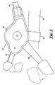
- Fig. 1 is a top view of a particular embodiment of a bicycle shifting apparatus (10) according to the present invention.
- Shifting apparatus (10) includes a mounting bracket (14) for mounting the shifting apparatus (10) to a handlebar (18) or other structural member of a bicycle; a housing (22) which houses the shifting components; a main lever (26) for causing the shifting apparatus (10) to pull on an inner wire (28, Fig. 2) of a shifting cable assembly (30); and a release lever (34) for causing the shifting apparatus to release the inner wire (28).
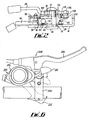
- shifting apparatus (10) is shown in Figs. 2 and 3.
- a lower cover (38) is mounted to bracket (14) for forming the lower portion of housing (22), and bracket (14) is adapted to be fastened to a handlebar (18) by a mounting screw (40).
- a main pivot post (44) extends through an opening (48) in mounting bracket (14).
- a takeup element (52) is rotatably mounted to main pivot post (44) through a bushing (56) and is biased in a cable unwinding direction by a spring (60).
- a cable retainer (64) is fastened to the end of inner cable (28) and is retained by an abutment (66) formed in takeup element (52) in a well known manner.
- control member (72) is fixed to take up element (52) so as to rotate integrally with it, and a retainer plate (76) is mounted over control member (72).
- control member (72) includes a plurality of position retaining teeth (80) and a plurality of drive teeth (84) for rotating and controlling the position of take up element (52) in conjunction with main lever (26) and release lever (34).
- An upper cover (88) is mounted to bracket (14) for forming the upper portion of housing (22).
- Release lever (34) is rotatably mounted to a release pivot post (92) which, in turn, is mounted to bracket (14).
- a spring (94) mounted between release lever (34) and release pivot post (92) for biasing release lever (34) to a home position (shown by a solid line in Fig. 1).
- a release pawl (98) is also rotatably mounted to release pivot post (92) and is biased in a clockwise direction by a release pawl spring (102).
- Release pawl (98) includes spaced apart jaws (104,106) for engaging position retaining teeth (80) on control member (72) in a manner discussed below. Release pawl (98) and release pawl spring (102) are retained on release pivot post (92) by a C-clip (110).
- a release lever tab (101) on release lever (34) cooperates with a pawl tab (103) on release pawl (98) to pivot release pawl counterclockwise in response to counterclockwise movement of release lever (34).
- Main lever (26) is rotatably mounted to main pivot post (44) by a bushing (112) and a retainer screw (113).
- a screw cover (115) is mounted above screw (113).
- a spacer (114) is disposed between main lever (26) and retainer plate (76), and a spring (118) is mounted between main lever (26) and a spring tab (122) on retainer plate (76) for biasing main lever (26) to a home position (shown by a solid line in Fig. 1).
- a drive pawl (130) is mounted to a drive pivot post (134) which, in turn, is mounted to main lever (26).
- Drive pawl (130) is biased in a clockwise direction by a spring (138), and both drive pawl (130) and spring (138) are retained on main pivot post (134) by a C-Clip (142).
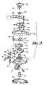
- Fig. 4 is a view illustrating the detailed structure of takeup element (52) and control member (72), and how the release pawl (98) and main pawl (130) cooperate with position retaining teeth (80) and drive teeth (84), respectively.
- Jaws (104,106) are spaced apart by a distance approximately equal to a distance between adjacent position retaining teeth (80).
- the bicycle transmission in this example is a derailleur/freewheel combination wherein a derailleur moves a drive chain from one freewheel sprocket to another.
- other transmissions could be used, if desired.
- the drive chain is engaged with the smallest freewheel sprocket when the position retaining tooth (80H) abuts against jaw (104) of release pawl (98), the drive chain is engaged with the second smallest freewheel sprocket when the position retaining tooth (80G) abuts against jaw (104) of release pawl (98), and so on until the chain is engaged with the largest freewheel sprocket wherein the position retaining tooth (80A) abuts against jaw (104) of release pawl (98).
- an engagement projection (140) of drive pawl (130) rests on an abutment (144) of retainer plate (76).
- the main lever (26) is rotated in the clockwise direction to the position shown by broken lines in Fig.1. This causes drive pawl (130) to move in the direction of the arrow shown in Fig. 4 so that engagement projection (140) of drive pawl (130) moves beyond abutment (144) on retainer plate (76), drops into the gap between drive tooth (84F) and (84G), and presses against the side of drive tooth (84G).
- release pawl (98) is rotatably mounted to release pivot post (92), release pawl (98) rotates counterclockwise when position retaining tooth (80F) presses against it, thus allowing position retaining tooth (80F) to move to the other side of jaw (104). Thereafter, when main lever (26) is released, spring (118) causes main lever (26) to return the position shown in solid lines in Fig. 1, and drive pawl (130) retracts to the position shown in Fig.4. Since takeup element (52) and control member (72) are biased in the counterclockwise direction by spring (60), control member begins to rotate. However, rotation of control member (72) stops when position retaining tooth (80F) abuts against jaw (104), thus maintaining takeup element (52) in the desired position.
- release lever (34) When the chain is to be shifted to a smaller gear, release lever (34) is rotated counterclockwise to the position shown in broken lines in Fig. 1. This causes release lever tab (101) to press against pawl tab (103) to rotate pawl (98) in the counterclockwise direction.
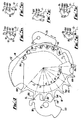
- Figs. 5A-5E show the movement of release pawl (98) in the case where the chain is to be shifted from the second smallest sprocket (the position shown in Fig. 4) to the smallest sprocket. Initially, position retaining tooth (80G) abuts against jaw (104) as shown in Figs. 4 and 5A.
- release lever tab (101) to disengage from pawl tab (103) as shown in Fig. 5D.
- release pawl Since release pawl is biased in the clockwise direction by spring (102), release pawl (98) begins to rotate in the clockwise direction, and jaw (106) moves up the side of position retaining tooth (80F) until the tip of jaw (106) clears the tip of position retaining tooth (80F).
- control member (72) which is biased in the counterclockwise direction by spring (60), moves counterclockwise until position retaining tooth (80H) abuts against jaw (104) as shown in Fig. 5E , thus completing the shifting operation.
- the thickness of the pawl must necessarily decrease, particularly the pawl jaws such as jaws (104,106) in release pawl (98).
- the pawl must then be fabricated from sintered metal or through some other high cost method. As the number of speeds continue to increase, the jaws become too thin, and a single pawl simply cannot be made to satisfactorily perform the function.
- the present invention solves this problem by setting a constant pitch (or space) between adjacent position retaining teeth despite the requirement of variable displacement of the transmission cable.
- a constant pitch between position retaining teeth (80B, 80C), (80C, 80D), (80D, 80E), (80E, 80F), and (80F, 80G).
- the constant pitch is 18°, but this is not critical. This actual pitch will depend on the particular application.
- the winding surface (68) is formed with an irregular shape. In this embodiment, the winding surface (68) has an increasing radius in the counterclockwise direction.
- the amount of cable displacement will vary despite the constant pitch of the position retaining teeth, and this variable displacement is accomplished without increasing the overall size of the shifting apparatus.
- the actual shape of the winding surface will also depend on the application, and it may either decrease in radius, remain constant, be flat, have a temporary spike, or have some shape depending upon the application.
- not all pairs of position retaining teeth need to have a constant pitch.
- the number of pairs of position retaining teeth having a constant pitch depends on the space savings desired, the number of speeds in the bicycle transmission, and other design considerations.
- the pitch of the position retaining teeth (80) allow control member (72) to accommodate seven or more speeds, and the control member may have a diameter of 30 mm or less
- Fig. 6 is a top view of an alternative embodiment of a shifting device (200) according to the present invention.
- an operation invention In this embodiment, an operation component (204) of shifting device (206) is mounted in close proximity to a brake operating unit (208) such that a first operating lever (212) is disposed below brake operating unit (208) and a second operating lever (216) is disposed above brake operating unit (208).
- first lever (212) functions as the main lever
- second lever (216) functions as the release lever, with movement indicated by the arrows, but the functions of the levers and their directions of movement could be reversed or altered as desired.
- the levers (212,216) could be disposed above or below the brake operating unit (208) at any location.
- levers (212,216) could be disposed above or below a mounting bracket (220), a brake lever (224), or any other portion of brake operating unit (208). This configuration makes it possible to shift and brake at the same time, and the levers can be seen quite easily for high performance operation.
- Fig. 7 is a cross sectional view of the shifting apparatus shown in Fig. 6. From inspection is should be readily apparent that the construction of operation component (204) is substantially the same as in the first embodiment, except the location of the main lever and the release lever has been reversed. Main pivot post (44) has been lengthened to accommodate bracket (14) which, in this embodiment, has been formed integrally with the brake operating unit (208). The components which correspond to the main components in the first embodiment are numbered the same, so a detailed description of them shall be omitted.
Priority Applications (1)
| Application Number | Priority Date | Filing Date | Title |
|---|---|---|---|
| DE69738242T DE69738242T3 (de) | 1996-01-19 | 1997-01-13 | Gangschaltungseinrichtung für ein Fahrrad |
Applications Claiming Priority (3)
| Application Number | Priority Date | Filing Date | Title |
|---|---|---|---|
| US08/588,659 US5730030A (en) | 1996-01-19 | 1996-01-19 | Shifting apparatus for bicycles having a brake operating unit disposed between first and second shifting levers |
| US588659 | 1996-01-19 | ||
| EP97300166A EP0785128B1 (de) | 1996-01-19 | 1997-01-13 | Gangschaltungseinrichtung für ein Fahrrad |
Related Parent Applications (2)
| Application Number | Title | Priority Date | Filing Date |
|---|---|---|---|
| EP97300166.2 Division | 1997-01-13 | ||
| EP97300166A Division EP0785128B1 (de) | 1996-01-19 | 1997-01-13 | Gangschaltungseinrichtung für ein Fahrrad |
Publications (4)
| Publication Number | Publication Date |
|---|---|
| EP1232940A2 true EP1232940A2 (de) | 2002-08-21 |
| EP1232940A3 EP1232940A3 (de) | 2003-04-09 |
| EP1232940B1 EP1232940B1 (de) | 2007-10-24 |
| EP1232940B2 EP1232940B2 (de) | 2012-08-22 |
Family
ID=24354762
Family Applications (2)
| Application Number | Title | Priority Date | Filing Date |
|---|---|---|---|
| EP02009203A Expired - Lifetime EP1232940B2 (de) | 1996-01-19 | 1997-01-13 | Gangschaltungseinrichtung für ein Fahrrad |
| EP97300166A Expired - Lifetime EP0785128B1 (de) | 1996-01-19 | 1997-01-13 | Gangschaltungseinrichtung für ein Fahrrad |
Family Applications After (1)
| Application Number | Title | Priority Date | Filing Date |
|---|---|---|---|
| EP97300166A Expired - Lifetime EP0785128B1 (de) | 1996-01-19 | 1997-01-13 | Gangschaltungseinrichtung für ein Fahrrad |
Country Status (5)
| Country | Link |
|---|---|
| US (1) | US5730030A (de) |
| EP (2) | EP1232940B2 (de) |
| CN (2) | CN1097542C (de) |
| DE (2) | DE69716787T2 (de) |
| TW (1) | TW556709U (de) |
Cited By (13)
| Publication number | Priority date | Publication date | Assignee | Title |
|---|---|---|---|---|
| EP1440878A2 (de) * | 2003-01-27 | 2004-07-28 | Shimano Inc. | Vorrichtung für eine Fahrradgangschaltung |
| EP1481883A1 (de) * | 2003-05-30 | 2004-12-01 | Shimano Inc. | Betätigungsvorrichtung für eine Fahrradgangschaltung |
| US7011590B2 (en) * | 2003-07-08 | 2006-03-14 | Shimano, Inc. | Shift assist apparatus for a bicycle transmission |
| EP1650121A2 (de) * | 2004-10-25 | 2006-04-26 | Shimano Inc. | Mechanismus zur Steuerung der Stellung einer Fahrradsteuerungsvorrichtung |
| EP1764298A1 (de) * | 2005-09-14 | 2007-03-21 | Shimano Inc. | Fahrradgetriebewechselgerät |
| EP1783043A2 (de) | 2005-11-04 | 2007-05-09 | Shimano Inc. | Steuerungseinrichtung für eine Fahrradgangschaltung |
| US7665382B2 (en) | 2006-02-07 | 2010-02-23 | Shimano Inc. | Bicycle shift control device |
| US7665383B2 (en) | 2006-01-31 | 2010-02-23 | Shimano Inc. | Bicycle shift control device |
| US7762157B2 (en) | 2005-10-06 | 2010-07-27 | Shimano, Inc. | Bicycle shift operating device with a multi-direction operating member |
| TWI510403B (zh) * | 2011-05-26 | 2015-12-01 | Shimano Kk | 腳踏車變速操作裝置 |
| US9797434B2 (en) | 2005-09-14 | 2017-10-24 | Shimano, Inc. | Bicycle shift operating device with a multi-direction operating member |
| CN108528625A (zh) * | 2017-03-06 | 2018-09-14 | 株式会社岛野 | 自行车操作装置 |
| EP2842860B1 (de) | 2013-08-26 | 2019-05-15 | SRAM Deutschland GmbH | Halte- und Freigabemechanik zum Halten und Freigeben einer Seilaufnahmevorrichtung |
Families Citing this family (50)
| Publication number | Priority date | Publication date | Assignee | Title |
|---|---|---|---|---|
| US5829313A (en) * | 1997-01-13 | 1998-11-03 | Shimano Inc. | Bicycle derailleur shifting mechanism having indexing configured for use with variety of chain sprocket sets |
| US5957002A (en) * | 1998-05-06 | 1999-09-28 | Industrial Development Bureau | Dual lever type derailleur gear unit for a bicycle |
| US6155132A (en) * | 1999-01-28 | 2000-12-05 | Shimano Inc. | Shifting unit for a bicycle |
| DE19915336A1 (de) † | 1999-04-03 | 2000-10-05 | Sram De Gmbh | Schalter für ein Fahrradgetriebe |
| TW448901U (en) * | 2000-05-19 | 2001-08-01 | Nat Science Council | Velocity control device |
| ITTO20010011A1 (it) * | 2001-01-11 | 2002-07-11 | Campagnolo Srl | Gruppo integrato di comando del cambio e del freno per una bicicletta. |
| ITTO20010010A1 (it) * | 2001-01-11 | 2002-07-11 | Campagnolo Srl | Gruppo integrato di comando del cambio e del freno per una bicicletta. |
| ITTO20011079A1 (it) | 2001-11-16 | 2003-05-16 | Campagnolo Srl | ,,dispositivo di comando del cambio per una bicicletta avente un manubrio con estremita' diritte,, |
| US6694840B2 (en) | 2002-01-10 | 2004-02-24 | Shimano Inc. | Bicycle shift operating device for bicycle transmission |
| DE10205278B4 (de) † | 2002-02-08 | 2019-03-14 | Sram Deutschland Gmbh | Freigabemechanismus |
| DE10213450B4 (de) * | 2002-03-26 | 2020-02-13 | Sram Deutschland Gmbh | Freigabeeinrichtung für Triggerschalter |
| DE10224196A1 (de) * | 2002-05-31 | 2003-12-11 | Sram De Gmbh | Seileinzugmechanik für Triggerschalter |
| ATE370060T1 (de) | 2004-02-06 | 2007-09-15 | Campagnolo Srl | Betätigungsvorrichtung für steuerkabel einer fahrradgangschaltung |
| US7281489B2 (en) * | 2004-04-29 | 2007-10-16 | Shimano, Inc. | Bicycle transmission gear indicating device |
| US7882763B2 (en) * | 2004-07-23 | 2011-02-08 | Shimano, Inc. | Shift control device for a bicycle transmission |
| ATE363427T1 (de) * | 2004-08-31 | 2007-06-15 | Campagnolo Srl | Betätigungsvorrichtung für steuerkabel einer fahrradgangschaltung, mit drehbarem tragkörper für die kabeltrommel |
| US7437969B2 (en) * | 2004-09-29 | 2008-10-21 | Shimano Inc. | Bicycle shift operating device |
| US8549954B2 (en) † | 2004-09-30 | 2013-10-08 | Shimano, Inc. | Bicycle shift device having a linearly sliding shift lever operated by a pivoting interface member |
| US20070261508A1 (en) * | 2004-10-30 | 2007-11-15 | Acenbrak Steven D | Ergonomic Shifter for a Bicycle |
| US7340975B2 (en) * | 2004-12-21 | 2008-03-11 | Shimano, Inc. | Bicycle control apparatus with a position setting idler member |
| US7802489B2 (en) * | 2005-06-01 | 2010-09-28 | Shimano Inc. | Bicycle control device |
| ATE419174T1 (de) | 2005-06-27 | 2009-01-15 | Campagnolo Srl | Steuerungsapparat für einen fahrradkettenumwerfer |
| JP4040059B2 (ja) * | 2005-11-30 | 2008-01-30 | 株式会社シマノ | 自転車用変速操作装置 |
| DE602006016343D1 (de) | 2006-01-23 | 2010-09-30 | Campagnolo Srl | Steuervorrichtung für fahrradkettenschaltung |
| DE602006015158D1 (de) | 2006-02-23 | 2010-08-12 | Campagnolo Srl | Fahrradbremsekontrollvorrichtung |
| US8375823B2 (en) * | 2006-07-26 | 2013-02-19 | Shimano Inc. | Bicycle shift control device |
| US7849764B2 (en) * | 2006-12-20 | 2010-12-14 | Shimano (Singapore) Pte., Ltd. | Bicycle shift operating device |
| US8777788B2 (en) * | 2007-02-08 | 2014-07-15 | Shimano Inc. | Bicycle component positioning device |
| ITMI20070239A1 (it) | 2007-02-09 | 2008-08-10 | Campagnolo Srl | Dispositivo di comando per un deragliatore di bicicletta |
| ITMI20070400A1 (it) | 2007-03-01 | 2008-09-02 | Campagnolo Srl | Dispositivo di comando per bicicletta e bicicletta comprendente tale dipsositivo |
| US8016705B2 (en) * | 2007-04-19 | 2011-09-13 | Shimano Inc. | Bicycle component positioning device |
| JP4382110B2 (ja) * | 2007-04-23 | 2009-12-09 | 株式会社シマノ | 自転車用操作装置 |
| US9334020B2 (en) * | 2007-04-26 | 2016-05-10 | Shimano Inc. | Bicycle component positioning device |
| ITMI20072230A1 (it) | 2007-11-23 | 2009-05-24 | Campagnolo Srl | Dispositivo di comando per bicicletta con manubrio ricurvo |
| US9199688B2 (en) * | 2008-06-13 | 2015-12-01 | Shimano Inc. | Bicycle control device |
| US9156518B2 (en) * | 2008-09-19 | 2015-10-13 | Shimano Inc. | Cable operating mechanism |
| US8886417B2 (en) | 2011-09-09 | 2014-11-11 | Sram, Llc | Bicycles with electronic shifting systems and methods |
| US8720301B2 (en) * | 2012-02-24 | 2014-05-13 | Shimano Inc. | Bicycle operating device |
| US9090303B2 (en) * | 2012-05-18 | 2015-07-28 | Shimano Inc. | Bicycle control device |
| US20140252746A1 (en) * | 2013-03-06 | 2014-09-11 | Specialized Bicycle Components, Inc. | Bicycle electronic display and shift lever mount |
| US10597109B2 (en) * | 2014-01-28 | 2020-03-24 | Shimano Inc. | Bicycle component positioning device |
| US10131405B2 (en) * | 2015-04-13 | 2018-11-20 | Shimano Inc. | Bicycle control device for operating a bicycle component |
| US9944350B2 (en) | 2016-01-11 | 2018-04-17 | Sram, Llc | Chain guide sensor and methods of controling a bicycle |
| CN106926969B (zh) * | 2017-03-16 | 2022-06-21 | 珠海蓝图控制器科技有限公司 | 一种自行车换挡器 |
| CN106892051B (zh) * | 2017-03-16 | 2022-05-17 | 珠海蓝图控制器科技有限公司 | 一种自行车换挡器 |
| CN106995035B (zh) * | 2017-04-17 | 2022-05-03 | 珠海蓝图控制器科技有限公司 | 一种自行车换挡器 |
| CN106904246B (zh) * | 2017-04-17 | 2022-05-03 | 珠海蓝图控制器科技有限公司 | 一种自行车换挡器 |
| US10780948B2 (en) * | 2018-12-10 | 2020-09-22 | Shimano Inc. | Bicycle operating device |
| CN109552549A (zh) * | 2018-12-25 | 2019-04-02 | 珠海迪瑞乐科技有限公司 | 自行车换挡器及自行车 |
| CN115123444B (zh) * | 2022-06-27 | 2023-09-08 | 胡建明 | 自行车变速系统及其组装方法 |
Citations (1)
| Publication number | Priority date | Publication date | Assignee | Title |
|---|---|---|---|---|
| US5203213A (en) | 1990-11-14 | 1993-04-20 | Shimano, Inc. | Bicycle speed control apparatus |
Family Cites Families (15)
| Publication number | Priority date | Publication date | Assignee | Title |
|---|---|---|---|---|
| CH248670A (de) † | 1946-02-26 | 1947-05-15 | Velosfabrik Cosmos B Schild & | Schaltvorrichtung für Wechselgetriebe, insbesondere von Fahr- und Motorrädern. |
| GB2012893B (en) † | 1978-01-12 | 1982-03-10 | Ti Raleigh Ind Ltd | Control means for elongate members |
| JPS5742158Y2 (de) * | 1978-10-06 | 1982-09-16 | ||
| GB2169065B (en) † | 1984-12-28 | 1987-12-23 | Sturmey Archer Ltd | Indexing mechanisms and controls embodying the same |
| JPS63129692U (de) * | 1987-02-18 | 1988-08-24 | ||
| JP2594270B2 (ja) † | 1987-03-20 | 1997-03-26 | 株式会社シマノ | 自転車用変速操作装置 |
| EP0352732B1 (de) * | 1988-07-29 | 1995-02-15 | Shimano Inc. | An der Lenkstange montierte Gangschaltungshebel |
| US5012692A (en) * | 1988-09-24 | 1991-05-07 | Shimano Industrial Company Limited | Change-speed lever apparatus for use in bicycle |
| US5241878A (en) † | 1988-11-29 | 1993-09-07 | Shimano, Inc. | Bicycle control device |
| JP3007641B2 (ja) * | 1989-07-06 | 2000-02-07 | 株式会社シマノ | 自転車のディレーラー用操作装置 |
| JPH05270475A (ja) * | 1992-03-23 | 1993-10-19 | Maeda Kogyo Kk | 自転車用変速操作装置 |
| EP0589048A4 (de) * | 1992-03-23 | 1994-11-30 | Maeda Ind | Getriebeschaltvorrichtung für fahrrad. |
| FR2701917B1 (fr) † | 1993-02-26 | 1995-07-07 | Sachs Ind Sa | Dispositif a deux organes de commande pour derailleur de cycle. |
| US5361645A (en) * | 1993-08-24 | 1994-11-08 | Industrial Technology Research Institute | Shift lever apparatus for use in bicycle |
| JP2607289Y2 (ja) * | 1993-12-28 | 2001-05-28 | 株式会社シマノ | 自転車用変速操作装置 |
-
1996
- 1996-01-19 US US08/588,659 patent/US5730030A/en not_active Expired - Lifetime
- 1996-01-26 TW TW090200541U patent/TW556709U/zh not_active IP Right Cessation
-
1997
- 1997-01-13 EP EP02009203A patent/EP1232940B2/de not_active Expired - Lifetime
- 1997-01-13 DE DE69716787T patent/DE69716787T2/de not_active Expired - Lifetime
- 1997-01-13 EP EP97300166A patent/EP0785128B1/de not_active Expired - Lifetime
- 1997-01-13 DE DE69738242T patent/DE69738242T3/de not_active Expired - Lifetime
- 1997-01-20 CN CN97109985A patent/CN1097542C/zh not_active Expired - Lifetime
- 1997-01-20 CN CN01134303.6A patent/CN1238218C/zh not_active Expired - Lifetime
Patent Citations (1)
| Publication number | Priority date | Publication date | Assignee | Title |
|---|---|---|---|---|
| US5203213A (en) | 1990-11-14 | 1993-04-20 | Shimano, Inc. | Bicycle speed control apparatus |
Cited By (25)
| Publication number | Priority date | Publication date | Assignee | Title |
|---|---|---|---|---|
| US7152497B2 (en) | 2003-01-27 | 2006-12-26 | Shimano, Inc. | Method and apparatus for shifting a bicycle transmission by multiple steps |
| EP1440878A2 (de) * | 2003-01-27 | 2004-07-28 | Shimano Inc. | Vorrichtung für eine Fahrradgangschaltung |
| EP1440878A3 (de) * | 2003-01-27 | 2005-02-02 | Shimano Inc. | Vorrichtung für eine Fahrradgangschaltung |
| CN100384688C (zh) * | 2003-01-27 | 2008-04-30 | 株式会社岛野 | 自行车控制装置的位置松开机构 |
| US7849765B2 (en) | 2003-05-30 | 2010-12-14 | Shimano Inc. | Bicycle shift operating device |
| US7194928B2 (en) | 2003-05-30 | 2007-03-27 | Shimano Inc. | Bicycle shift operating device |
| EP1481883A1 (de) * | 2003-05-30 | 2004-12-01 | Shimano Inc. | Betätigungsvorrichtung für eine Fahrradgangschaltung |
| US7011590B2 (en) * | 2003-07-08 | 2006-03-14 | Shimano, Inc. | Shift assist apparatus for a bicycle transmission |
| EP1650121A2 (de) * | 2004-10-25 | 2006-04-26 | Shimano Inc. | Mechanismus zur Steuerung der Stellung einer Fahrradsteuerungsvorrichtung |
| US8181553B2 (en) | 2004-10-25 | 2012-05-22 | Shimano Inc. | Position control mechanism for bicycle control device |
| CN100398392C (zh) * | 2004-10-25 | 2008-07-02 | 株式会社岛野 | 用于自行车控制装置的位置控制机构 |
| EP1650121A3 (de) * | 2004-10-25 | 2006-11-02 | Shimano Inc. | Mechanismus zur Steuerung der Stellung einer Fahrradsteuerungsvorrichtung |
| EP1764298A1 (de) * | 2005-09-14 | 2007-03-21 | Shimano Inc. | Fahrradgetriebewechselgerät |
| US9797434B2 (en) | 2005-09-14 | 2017-10-24 | Shimano, Inc. | Bicycle shift operating device with a multi-direction operating member |
| CN1931661B (zh) * | 2005-09-14 | 2010-12-08 | 株式会社岛野 | 自行车用变速操作装置 |
| US7762157B2 (en) | 2005-10-06 | 2010-07-27 | Shimano, Inc. | Bicycle shift operating device with a multi-direction operating member |
| US7721621B2 (en) | 2005-11-04 | 2010-05-25 | Shimano Inc. | Bicycle shift control mechanism |
| EP1783043A3 (de) * | 2005-11-04 | 2008-01-16 | Shimano Inc. | Steuerungseinrichtung für eine Fahrradgangschaltung |
| EP1783043A2 (de) | 2005-11-04 | 2007-05-09 | Shimano Inc. | Steuerungseinrichtung für eine Fahrradgangschaltung |
| US7665383B2 (en) | 2006-01-31 | 2010-02-23 | Shimano Inc. | Bicycle shift control device |
| US7665382B2 (en) | 2006-02-07 | 2010-02-23 | Shimano Inc. | Bicycle shift control device |
| TWI510403B (zh) * | 2011-05-26 | 2015-12-01 | Shimano Kk | 腳踏車變速操作裝置 |
| EP2842860B1 (de) | 2013-08-26 | 2019-05-15 | SRAM Deutschland GmbH | Halte- und Freigabemechanik zum Halten und Freigeben einer Seilaufnahmevorrichtung |
| CN108528625A (zh) * | 2017-03-06 | 2018-09-14 | 株式会社岛野 | 自行车操作装置 |
| CN108528625B (zh) * | 2017-03-06 | 2020-05-12 | 株式会社岛野 | 自行车操作装置 |
Also Published As
| Publication number | Publication date |
|---|---|
| CN1491850A (zh) | 2004-04-28 |
| US5730030A (en) | 1998-03-24 |
| EP0785128B1 (de) | 2002-11-06 |
| TW556709U (en) | 2003-10-01 |
| EP0785128A2 (de) | 1997-07-23 |
| EP1232940B2 (de) | 2012-08-22 |
| DE69738242T2 (de) | 2008-12-04 |
| EP0785128A3 (de) | 1997-12-10 |
| CN1238218C (zh) | 2006-01-25 |
| DE69716787D1 (de) | 2002-12-12 |
| EP1232940B1 (de) | 2007-10-24 |
| EP1232940A3 (de) | 2003-04-09 |
| CN1097542C (zh) | 2003-01-01 |
| CN1171354A (zh) | 1998-01-28 |
| DE69716787T2 (de) | 2003-11-20 |
| DE69738242D1 (de) | 2007-12-06 |
| DE69738242T3 (de) | 2013-01-24 |
Similar Documents
| Publication | Publication Date | Title |
|---|---|---|
| EP1232940B1 (de) | Gangschaltungseinrichtung für ein Fahrrad | |
| EP0853035B1 (de) | Schalteinrichtung für ein Fahrradgetriebe | |
| US7526979B2 (en) | Bicycle shift position control mechanism | |
| EP0810150B1 (de) | Steuerungseinrichtung für eine Fahrradgangschaltung | |
| US7152497B2 (en) | Method and apparatus for shifting a bicycle transmission by multiple steps | |
| EP2374707B1 (de) | Steuerungsvorrichtung für eine Fahrradgangschaltung | |
| US20020139218A1 (en) | Bicycle control device | |
| US8069749B2 (en) | Shift control device for a bicycle transmission | |
| US6899649B2 (en) | Motor unit for an assisting apparatus for changing speeds in a bicycle transmission | |
| US6718844B2 (en) | Twist-grip shift control device for a bicycle | |
| EP1350715A2 (de) | Drehgriffschalter für Fahrrad | |
| US6868752B2 (en) | Assisting apparatus for changing speeds in a bicycle transmission | |
| US6848336B2 (en) | Bicycle shift control device biased to a neutral position | |
| EP1378437B1 (de) | Steuerungseinrichtung für eine Fahrradgangschaltung | |
| JPS6235540B2 (de) | ||
| WO2001092091A2 (en) | Apparatus for shifting a transmission for bicycles |
Legal Events
| Date | Code | Title | Description |
|---|---|---|---|
| PUAI | Public reference made under article 153(3) epc to a published international application that has entered the european phase |
Free format text: ORIGINAL CODE: 0009012 |
|
| 17P | Request for examination filed |
Effective date: 20020424 |
|
| AC | Divisional application: reference to earlier application |
Ref document number: 785128 Country of ref document: EP |
|
| AK | Designated contracting states |
Kind code of ref document: A2 Designated state(s): DE FR IT |
|
| PUAL | Search report despatched |
Free format text: ORIGINAL CODE: 0009013 |
|
| AK | Designated contracting states |
Designated state(s): DE FR IT Kind code of ref document: A3 Designated state(s): DE FR IT |
|
| AKX | Designation fees paid |
Designated state(s): DE FR IT |
|
| RAP1 | Party data changed (applicant data changed or rights of an application transferred) |
Owner name: SHIMANO INC. |
|
| 17Q | First examination report despatched |
Effective date: 20060706 |
|
| GRAP | Despatch of communication of intention to grant a patent |
Free format text: ORIGINAL CODE: EPIDOSNIGR1 |
|
| GRAS | Grant fee paid |
Free format text: ORIGINAL CODE: EPIDOSNIGR3 |
|
| GRAA | (expected) grant |
Free format text: ORIGINAL CODE: 0009210 |
|
| AC | Divisional application: reference to earlier application |
Ref document number: 0785128 Country of ref document: EP Kind code of ref document: P |
|
| AK | Designated contracting states |
Kind code of ref document: B1 Designated state(s): DE FR IT |
|
| REF | Corresponds to: |
Ref document number: 69738242 Country of ref document: DE Date of ref document: 20071206 Kind code of ref document: P |
|
| ET | Fr: translation filed | ||
| PLBI | Opposition filed |
Free format text: ORIGINAL CODE: 0009260 |
|
| PLAX | Notice of opposition and request to file observation + time limit sent |
Free format text: ORIGINAL CODE: EPIDOSNOBS2 |
|
| 26 | Opposition filed |
Opponent name: SRAM DEUTSCHLAND GMBH Effective date: 20080723 |
|
| PLAF | Information modified related to communication of a notice of opposition and request to file observations + time limit |
Free format text: ORIGINAL CODE: EPIDOSCOBS2 |
|
| PLAF | Information modified related to communication of a notice of opposition and request to file observations + time limit |
Free format text: ORIGINAL CODE: EPIDOSCOBS2 |
|
| PLBB | Reply of patent proprietor to notice(s) of opposition received |
Free format text: ORIGINAL CODE: EPIDOSNOBS3 |
|
| PGFP | Annual fee paid to national office [announced via postgrant information from national office to epo] |
Ref country code: FR Payment date: 20120202 Year of fee payment: 16 |
|
| PGFP | Annual fee paid to national office [announced via postgrant information from national office to epo] |
Ref country code: IT Payment date: 20120118 Year of fee payment: 16 |
|
| PUAH | Patent maintained in amended form |
Free format text: ORIGINAL CODE: 0009272 |
|
| STAA | Information on the status of an ep patent application or granted ep patent |
Free format text: STATUS: PATENT MAINTAINED AS AMENDED |
|
| 27A | Patent maintained in amended form |
Effective date: 20120822 |
|
| AK | Designated contracting states |
Kind code of ref document: B2 Designated state(s): DE FR IT |
|
| REG | Reference to a national code |
Ref country code: DE Ref legal event code: R102 Ref document number: 69738242 Country of ref document: DE |
|
| REG | Reference to a national code |
Ref country code: DE Ref legal event code: R102 Ref document number: 69738242 Country of ref document: DE Effective date: 20120822 |
|
| REG | Reference to a national code |
Ref country code: DE Ref legal event code: R082 Ref document number: 69738242 Country of ref document: DE Representative=s name: MURGITROYD & COMPANY, DE |
|
| REG | Reference to a national code |
Ref country code: FR Ref legal event code: ST Effective date: 20130930 |
|
| PG25 | Lapsed in a contracting state [announced via postgrant information from national office to epo] |
Ref country code: FR Free format text: LAPSE BECAUSE OF NON-PAYMENT OF DUE FEES Effective date: 20130131 |
|
| PG25 | Lapsed in a contracting state [announced via postgrant information from national office to epo] |
Ref country code: IT Free format text: LAPSE BECAUSE OF NON-PAYMENT OF DUE FEES Effective date: 20130113 |
|
| PGFP | Annual fee paid to national office [announced via postgrant information from national office to epo] |
Ref country code: DE Payment date: 20150106 Year of fee payment: 19 |
|
| REG | Reference to a national code |
Ref country code: DE Ref legal event code: R119 Ref document number: 69738242 Country of ref document: DE |
|
| PG25 | Lapsed in a contracting state [announced via postgrant information from national office to epo] |
Ref country code: DE Free format text: LAPSE BECAUSE OF NON-PAYMENT OF DUE FEES Effective date: 20160802 |