EP1232866A1 - Fluid ejection systems and methods with secondary dielectric fluid - Google Patents
Fluid ejection systems and methods with secondary dielectric fluid Download PDFInfo
- Publication number
- EP1232866A1 EP1232866A1 EP02003373A EP02003373A EP1232866A1 EP 1232866 A1 EP1232866 A1 EP 1232866A1 EP 02003373 A EP02003373 A EP 02003373A EP 02003373 A EP02003373 A EP 02003373A EP 1232866 A1 EP1232866 A1 EP 1232866A1
- Authority
- EP
- European Patent Office
- Prior art keywords
- fluid
- diaphragm
- secondary dielectric
- dielectric fluid
- chamber
- Prior art date
- Legal status (The legal status is an assumption and is not a legal conclusion. Google has not performed a legal analysis and makes no representation as to the accuracy of the status listed.)
- Granted
Links
Images


Classifications
-
- B—PERFORMING OPERATIONS; TRANSPORTING
- B41—PRINTING; LINING MACHINES; TYPEWRITERS; STAMPS
- B41J—TYPEWRITERS; SELECTIVE PRINTING MECHANISMS, i.e. MECHANISMS PRINTING OTHERWISE THAN FROM A FORME; CORRECTION OF TYPOGRAPHICAL ERRORS
- B41J2/00—Typewriters or selective printing mechanisms characterised by the printing or marking process for which they are designed
- B41J2/005—Typewriters or selective printing mechanisms characterised by the printing or marking process for which they are designed characterised by bringing liquid or particles selectively into contact with a printing material
- B41J2/01—Ink jet
- B41J2/135—Nozzles
- B41J2/14—Structure thereof only for on-demand ink jet heads
- B41J2/14314—Structure of ink jet print heads with electrostatically actuated membrane
-
- B—PERFORMING OPERATIONS; TRANSPORTING
- B41—PRINTING; LINING MACHINES; TYPEWRITERS; STAMPS
- B41J—TYPEWRITERS; SELECTIVE PRINTING MECHANISMS, i.e. MECHANISMS PRINTING OTHERWISE THAN FROM A FORME; CORRECTION OF TYPOGRAPHICAL ERRORS
- B41J2/00—Typewriters or selective printing mechanisms characterised by the printing or marking process for which they are designed
- B41J2/005—Typewriters or selective printing mechanisms characterised by the printing or marking process for which they are designed characterised by bringing liquid or particles selectively into contact with a printing material
- B41J2/01—Ink jet
- B41J2/015—Ink jet characterised by the jet generation process
- B41J2/04—Ink jet characterised by the jet generation process generating single droplets or particles on demand
- B41J2002/041—Electromagnetic transducer
Definitions
- This invention relates to micromachined or microelectromechanical system based fluid ejectors and fluid ejection methods.
- Fluid ejectors have been developed for inkjet recording or printing.
- Ink jet recording apparatus offer numerous benefits, including extremely quiet operation when recording, high speed printing, a high degree of freedom in ink selection, and the ability to use low-cost plain paper.
- the so-called "drop-on-demand" drive method where ink is output only when required for recording, is now the conventional approach.
- the drop-on-demand drive method makes it unnecessary to recover ink not needed for recording.
- Fluid ejectors for inkjet printing include one or more nozzles which allow the formation and control of small ink droplets to permit high resolution, resulting in the ability to print sharper characters with improved tonal resolution.
- drop-on-demand inkjet print heads are generally used for high resolution printers.
- Drop-on-demand technology generally uses some type of pulse generator to form and eject drops.
- a chamber having an ink nozzle may be fitted with a piezoelectric wall that is deformed when a voltage is applied.
- the fluid is forced out of the nozzle orifice as a drop.
- the drop then impinges directly on an associated printing surface.
- a piezoelectric device as a driver is described in JP B-1990-51734.
- Another type of print head uses bubbles formed by heat pulses to force fluid out of the nozzle.
- the drops are separated from the ink supply when the bubbles collapse.
- Use of pressure generated by heating the ink to generate bubbles is described in JP B-1986-59911.
- Yet another type of drop-on-demand print head incorporates an electrostatic actuator.
- This type of print head utilizes electrostatic force to eject the ink.
- Examples of such electrostatic print heads are disclosed in U.S. Patent 4,520,375 to Kroll and Japanese Laid-Open Patent Publication No. 289351/90.
- the ink jet head disclosed in the 375 patent uses an electrostatic actuator comprising a diaphragm that constitutes a part of an ink ejection chamber and a base plate disposed outside of the ink ejection chamber opposite to the diaphragm.
- the ink jet head ejects ink droplets through a nozzle communicating with the ink ejection chamber, by applying a time varying voltage between the diaphragm and the base plate.
- the diaphragm and the base plate thus act as a capacitor, which causes the diaphragm to be set into mechanical motion and the fluid to exit responsive to the diaphragm's motion.
- the ink jet head discussed in the Japan 351 distorts its diaphragm by applying a voltage to an electrostatic actuator fixed on the diaphragm. This result in suction of ink into an ink ejection chamber. Once the voltage is removed, the diaphragm is restored to its non-distorted condition, ejecting ink from the ink ejection chamber.
- Fluid drop ejectors may be used not only for printing, but also for depositing photoresist and other liquids in the semiconductor and flat panel display industries, for delivering drug and biological samples, for delivering multiple chemicals for chemical reactions, for handling DNA sequences, for delivering drugs and biological materials for interaction studies and assaying, and for depositing thin and narrow layers of plastics for usable as permanent and/or removable gaskets in micro-machines.
- the systems and methods of this invention provide increased electrostatic force for fluid ejection in an electrostatic fluid ejector.
- the systems and methods of this invention separately provide greater fluid ejection efficiency.
- the systems and methods of this invention separately provide greater fluid ejection velocity with an electrostatic fluid ejector.
- the systems and methods of this invention separately provide for compensation within a sealed chamber of a secondary dielectric fluid.
- the systems and methods of this invention separately provide an actively powered ejection cycle for ejecting fluid from a fluid ejector.
- the systems and methods of this invention separately provide increased force on a fluid over the cycle of a fluid ejector.
- the systems and methods of this invention separately provide isolation of the electrostatic field from the primary fluid or fluid to be ejected.
- the systems and methods of this invention separately provide increased latitude in primary fluid design.
- the systems and methods of this invention separately utilize a high performance secondary dielectric fluid.
- a sealed diaphragm that is used to eject a fluid from a fluid ejector that contains a secondary dielectric fluid.
- the secondary dielectric fluid is a liquid.
- the secondary dielectric fluid is substantially incompressible.
- the secondary dielectric fluid is a high performance dielectric fluid or dielectrically enhanced fluid.
- a sealed diaphragm chamber is connected to a secondary dielectric reservoir.
- a secondary dielectric feed hole is formed through a substrate to be in communication with the diaphragm chamber.
- a channel is formed to be in communication with the sealed diaphragm chamber.
- a fluid ejection system comprises a containment structure for a fluid to be ejected, an electrode and a sealed diaphragm that at least partly defines a chamber in which a secondary dielectric fluid is provided.
- a fluid ejection system comprises a sealed diaphragm arrangement including at least one diaphragm portion and a diaphragm chamber defined at least partially by the at least one diaphragm portion.
- a nozzle hole is located over the at least one diaphragm portion.
- An ejection chamber that receives a primary fluid to be ejected is defined between the nozzle hole and the least one diaphragm portion.
- a secondary dielectric fluid reservoir containing a secondary dielectric fluid is in fluid communication with the diaphragm chamber to supply the secondary dielectric fluid to the diaphragm chamber.
- the system further comprises:
- a fluid ejection system operates on the principle of electrostatic or magnetic attraction.
- the fluid ejection system includes a sealed diaphragm arrangement having at least one diaphragm portion and a diaphragm chamber defined at least partially by the at least one diaphragm portion, a nozzle hole located over the at least one diaphragm portion, an ejection chamber defined between the nozzle hole and the least one diaphragm portion and a secondary dielectric fluid reservoir containing a secondary dielectric fluid.
- the ejection chamber receives a primary fluid to be ejected, which may or may not be a dielectric fluid.
- the secondary dielectric fluid reservoir is in fluid communication with the diaphragm chamber to supply the secondary dielectric fluid to the diaphragm chamber.
- the secondary dielectric fluid is a liquid, a substantially incompressible fluid, and/or a high performance dielectric fluid having a dielectric constant greater than 1.
- the fluid ejection system includes an electrode arrangement that causes the diaphragm portion to deflect when a drive signal is applied to at least one electrode of the electrode arrangement to generate an electrostatic field between the at least one electrode and the diaphragm portion.
- the diaphragm portion is attracted towards the at least one electrode by an electrostatic force of the generated electrostatic field.
- the secondary dielectric fluid supplied to the diaphragm chamber is allowed to flow into or out of the secondary dielectric fluid reservoir.
- the electrostatic force need not compress or expand the volume of the secondary dielectric fluid in the diaphragm chamber to deflect the diaphragm portion. Accordingly, substantially incompressible fluids and/or high performance dielectric fluids having a dielectric constant greater than 1 may be advantageously used for the secondary dielectric fluid.
- the electrode is situated so that the diaphragm portion deflects into the ejection chamber defined between the nozzle hole and the diaphragm portion, a drop of fluid is ejected through the nozzle hole when the diaphragm portion deflects. After a drop is ejected, the movement of the diaphragm portion is reversed, either through normal resilient restoration actions of the deformed diaphragm portion or through an applied force. The reversed movement of the diaphragm portion may be used to refill the ejection chamber with fluid to be ejected.
- the electrode If the electrode is situated so that the diaphragm portion deflects away from the ejection chamber, fluid is overfilled in the ejection chamber when the diaphragm portion deflects.
- the drive signal applied to the electrode is removed, the movement of the diaphragm portion is reversed, either through normal resilient restoration actions of the deformed diaphragm portion or through an applied force, to eject a drop of fluid.
- the fluid ejection systems of this invention may be easily produced via monolithic batch fabrication based on the common production technique of silicon-based surface micro-machining and would have the potential for very low cost of production, high reliability and "on demand” drop size modulation.
- the systems and methods of this invention may refer to aspects specific to silicon based surface micromachining, in fact other materials and production techniques for the fluid ejection systems of this invention are possible.
- the systems and methods of the invention may be utilized in any mechanical configuration of such an ejector (e.g., "roof shooter” or "edge shooter") and in any size array of ejectors.
- Figs. 1-3 show a simplified illustration of a single ejector in a "roof shooter" configuration is shown in Figs. 1-3.
- the ejector 100 includes a base plate 110, an electrode 120, a diaphragm 130 and a faceplate 140 with a nozzle hole 142.
- a diaphragm chamber 132 is sealed from the fluid to be ejected by the diaphragm 130. In this example, air is contained in the diaphragm chamber 132.
- Fig. 3 shows an initial state of operation with the diaphragm 130 in an undeflected state.
- Fig. 1 shows an electrostatic field is generated across the air gap between the electrode 120 and the diaphragm 130, the diaphragm 130 is deflected into a deflected state.
- fluid is drawn into the space created by the deflected diaphragm 130 from a reservoir, which may be located at any part of the periphery of the ejector 100.
- Fig. 2 shows an intermediate non-static state between the deflected and undeflected states shown in Figs. 1 and 3, respectively.
- the resilient restoration force is transferred to the fluid, causing some fluid to be forced back into the reservoir and some fluid to be ejected through the nozzle hole 142, as shown in Fig. 3. This action is somewhat analogous to a "cocked" spring.
- the percentage of the fluid which is expelled as a drop, relative to the amount of fluid being moved by the diaphragm 130, may be controlled through specific design parameters of the ejector 100.
- Such parameters include the size of the diaphragm 130, the applied force, the distance between the diaphragm 130 and the faceplate 140 and other unique features that may help govern flow, such as, for example, incorporating valves into the ejector 100.
- This volumetric efficiency can be enhanced by optimizing the "cocked" geometry of the diaphragm.
- a key parameter limiting the available force exerted on the fluid during ejection is the dielectric constant of the compressible fluid in the diaphragm chamber 132.
- air has a dielectric constant of approximately 1. While using air as the working dielectric may offer simplified manufacturing, doing so may limit the overall performance of the ejector 100. For example, a much higher voltage is required to deflect the diaphragm, which may result in increased power dissipation in the ejector 100.
- a fluid ejector 200 has a sealed diaphragm arrangement comprising a diaphragm portion 230 and a diaphragm chamber 232.
- the diaphragm chamber 232 contains an incompressible secondary dielectric fluid 234.
- the sealed diaphragm arrangement is formed on a substrate 210.
- An electrode 220 is situated on the substrate 210 opposite the diaphragm portion 230.
- a faceplate 240 with a nozzle hole 242 is situated on a side of the diaphragm portion 230 opposite the substrate 210.
- An ejection chamber 250 is defined between the faceplate 240 and the diaphragm portion 230.
- a fluid 252 to be ejected is supplied to the ejection chamber 250 of the fluid ejector 200 from a fluid reservoir, which may be located separate from the fluid ejector 200.
- a fluid reservoir 260 may be disposed on a side of the substrate 210 opposite the diaphragm portion 230.
- an inlet hole 254 may be formed through the substrate 210 that leads to the fluid reservoir 260.
- the secondary dielectric fluid 234 may be supplied from a secondary dielectric fluid reservoir 270, which may also be located separate from the fluid ejector 200. As shown in Figs. 4-6, the secondary dielectric fluid reservoir 270 may be disposed on a side of the substrate 210 opposite the diaphragm portion 230. As shown in Fig. 7, a passageway 236 may be formed through the substrate 210 that leads to the secondary dielectric fluid reservoir 270.
- the fluid ejector 200 operates on the principle of electrostatic attraction as illustrated in Figs. 4-6.
- Fig. 4 shows an initial state and Figs. 5-6 show a fluid drop being ejected.
- a drive signal is applied to the electrode 220 to generated an electrostatic field between the electrode 220 and the diaphragm portion 230.
- an attractive electrostatic force causes the diaphragm portion 230 to deflect towards the electrode 220 into a deformed state.
- the fluid 252 is drawn into the ejection chamber 250 to overfill the ejection chamber 250.
- a pressure is transmitted from the deflecting diaphragm portion 230 to the secondary dielectric fluid 234 causing the secondary dielectric fluid 234 to flow through the passageway 236 and into the secondary dielectric fluid reservoir 270.
- the electrostatic force need not overcome the incompressibilty of the secondary dielectric fluid 234 to deflect the diaphragm portion 230.
- the drive signal is then removed from the electrode 220 so that the movement of the diaphragm portion 230 is reversed, either through resilient restoration actions of the deformed diaphragm portion 230 and/or through an applied force, to expel a drop of the fluid 252 through the nozzle hole 242.
- a second electrode may be associated with the faceplate 240 to apply a second electrostatic force to attract the diaphragm portion 230 in the opposite direction.
- the percentage of the fluid 252 that is expelled as a drop, relative to the amount of fluid being moved by the diaphragm portion 230, may be controlled through specific design parameters of the ejector 200.
- the parameters include the size of the diaphragm portion 230, the applied force(s), the distances between the diaphragm portion 230 and the faceplate 240 and other unique features that may help govern flow, such as, for example, incorporating valves into the ejector 200.
- a high-performance dielectric fluid is used for the secondary dielectric fluid to enable significantly higher forces to be applied to the fluid.
- distilled water has a dielectric constant, ⁇ , of about 78. This means that a diaphragm structure may be designed to allow about 78 times the "spring" force to be applied to the fluid to be ejected as compared to an approach using air. Distilled water also has a very low conductivity, about 10 -6 S/m, which enables low energy usage.
- Other dielectric fluids such as S-fluids, T-fluids, oils, organic solutions, etc. may be used.
- S-fluids and T-fluids are test fluids having the same composition as various inks such as, for example, dye-based aqueous inks, microemulsion inks, liquid crystalline inks, hotmelt inks, liposomic inks, and pigmented inks, without any colorants.
- Possible organic fluids include, for example, ethylene glycol, propanediol, diethylene glycol, glycerol, trihydroxypropane, butanediol, pentanediol and dimethyl sulfoxide.
- the design considerations for the secondary dielectric fluid include its dielectric constant, its wetting characteristics and its stability for electric field strength and applied voltage. Viscosity is also a consideration for the desired fluid flow with movement of the diaphragm.
- Fig. 8 shows a second exemplary embodiment of a fluid ejector 300 according to this invention.
- the fluid ejector 300 has a sealed diaphragm arrangement comprising a diaphragm portion 330 and a diaphragm chamber 332.
- the diaphragm chamber 332 contains a high-performance dielectric fluid 334.
- the sealed diaphragm arrangement is formed on a substrate 310.
- An electrode 320 is situated on the substrate 310 opposite the diaphragm portion 330.
- a faceplate 340 with a nozzle hole 342 is situated on a side of the diaphragm portion 330 opposite the substrate 310.
- An ejection chamber 350 is defined between the faceplate 340 and the diaphragm portion 330.
- a fluid 352 to be ejected is supplied to the ejection chamber 350 of the fluid ejector 300 from a fluid reservoir 360 formed on a side of the substrate 310 opposite the diaphragm portion 330.
- an inlet hole 354 is formed through the substrate 310 that leads to the fluid reservoir 360.
- the secondary dielectric fluid 334 is supplied from a secondary dielectric fluid reservoir 370 that is also formed on a side of the substrate 310 opposite the diaphragm portion 330. As shown in Fig. 8, a passageway 336 is formed through the substrate 310 that leads to the secondary dielectric fluid reservoir 370.
- the fluid reservoir 360 and the secondary dielectric fluid reservoir 370 may include packing foam 380 that reduces "sloshing" and formation of bubbles in the respective fluids.
- the fluid reservoir 360 and the secondary dielectric fluid reservoir 370 may be sealed tanks and may be permanently attached to the substrate 310.
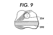
- the fluid ejector 300 includes a "burping" channel 390 that allows the diaphragm chamber 332 to be completely filled with the secondary dielectric fluid 334.
- the channel 390 may be in fluid communication with atmosphere or with an overflow basin 392.
- the second exemplary embodiment has the "burping" channel 390 offset from the inlet hole 354 so that the fluid 352 can reach the ejection chamber 350 without interference.
- any air in the diaphragm chamber 332 is purged or "burped" from the diaphragm chamber 332 through the channel 390.
- Some of the secondary dielectric fluid 334 may also be forced out of the diaphragm chamber 332 through the channel 390 to ensure that all of the air has been purged.
- the overflow basin 392 provides a convenient receptacle for the excess secondary dielectric fluid 334.
- the fluid reservoir 360 and the secondary dielectric fluid reservoir 370 may be common to each of the fluid ejectors 300.
- the "burping" channel 390 and the overflow basin 392 may be common to each of the fluid ejectors 300. Further, once the diaphragm chamber 332 is completely filled, the channel 390 may remain open or may be sealed.
- the fluid ejector 300 operates as described above with respect to the first embodiment.
- the inlet hole 354 and the passageway 336 may be formed through the substrate 310 using a modified Bosch etch. Such a method is disclosed in copending U.S. Patent Application Serial No. 09/723,243, which is incorporated herein by reference in its entirety.
- a modulated drive signal as disclosed in copending U.S. Patent Application Serial No. 09/718,480, which is incorporated herein by reference in its entirety, may be used to increase dielectric fluid breakdown latitude.
- the essence of this approach is using a substantially constant electrostatic field throughout the "cocking" motion of the diaphragm.
- the input drive signal may be suitably tailored to obtain substantially the maximum possible field strength.
- the drive signal may be tailored to have certain specified characteristics.
- the system may be driven at a suitably high frequency.
- a bi-polar pulse train at the desired frequency may be used.
- the diaphragm may be configured as a bi-directional diaphragm as disclosed in copending U.S. Patent Application Serial No. 09/718, 476, filed November 24, 2000.
Abstract
Description
- This invention relates to micromachined or microelectromechanical system based fluid ejectors and fluid ejection methods.
- Fluid ejectors have been developed for inkjet recording or printing. Ink jet recording apparatus offer numerous benefits, including extremely quiet operation when recording, high speed printing, a high degree of freedom in ink selection, and the ability to use low-cost plain paper. The so-called "drop-on-demand" drive method, where ink is output only when required for recording, is now the conventional approach. The drop-on-demand drive method makes it unnecessary to recover ink not needed for recording.
- Fluid ejectors for inkjet printing include one or more nozzles which allow the formation and control of small ink droplets to permit high resolution, resulting in the ability to print sharper characters with improved tonal resolution. In particular, drop-on-demand inkjet print heads are generally used for high resolution printers.
- Drop-on-demand technology generally uses some type of pulse generator to form and eject drops. For example, in one type of print head, a chamber having an ink nozzle may be fitted with a piezoelectric wall that is deformed when a voltage is applied. As a result of the deformation, the fluid is forced out of the nozzle orifice as a drop. The drop then impinges directly on an associated printing surface. Use of such a piezoelectric device as a driver is described in JP B-1990-51734.
- Another type of print head uses bubbles formed by heat pulses to force fluid out of the nozzle. The drops are separated from the ink supply when the bubbles collapse. Use of pressure generated by heating the ink to generate bubbles is described in JP B-1986-59911.
- Yet another type of drop-on-demand print head incorporates an electrostatic actuator. This type of print head utilizes electrostatic force to eject the ink. Examples of such electrostatic print heads are disclosed in U.S. Patent 4,520,375 to Kroll and Japanese Laid-Open Patent Publication No. 289351/90. The ink jet head disclosed in the 375 patent uses an electrostatic actuator comprising a diaphragm that constitutes a part of an ink ejection chamber and a base plate disposed outside of the ink ejection chamber opposite to the diaphragm. The ink jet head ejects ink droplets through a nozzle communicating with the ink ejection chamber, by applying a time varying voltage between the diaphragm and the base plate. The diaphragm and the base plate thus act as a capacitor, which causes the diaphragm to be set into mechanical motion and the fluid to exit responsive to the diaphragm's motion. On the other hand, the ink jet head discussed in the Japan 351 distorts its diaphragm by applying a voltage to an electrostatic actuator fixed on the diaphragm. This result in suction of ink into an ink ejection chamber. Once the voltage is removed, the diaphragm is restored to its non-distorted condition, ejecting ink from the ink ejection chamber.
- Fluid drop ejectors may be used not only for printing, but also for depositing photoresist and other liquids in the semiconductor and flat panel display industries, for delivering drug and biological samples, for delivering multiple chemicals for chemical reactions, for handling DNA sequences, for delivering drugs and biological materials for interaction studies and assaying, and for depositing thin and narrow layers of plastics for usable as permanent and/or removable gaskets in micro-machines.
- The systems and methods of this invention provide increased electrostatic force for fluid ejection in an electrostatic fluid ejector.
- The systems and methods of this invention separately provide greater fluid ejection efficiency.
- The systems and methods of this invention separately provide greater fluid ejection velocity with an electrostatic fluid ejector.
- The systems and methods of this invention separately provide for compensation within a sealed chamber of a secondary dielectric fluid.
- The systems and methods of this invention separately provide an actively powered ejection cycle for ejecting fluid from a fluid ejector.
- The systems and methods of this invention separately provide increased force on a fluid over the cycle of a fluid ejector.
- The systems and methods of this invention separately provide isolation of the electrostatic field from the primary fluid or fluid to be ejected.
- The systems and methods of this invention separately provide increased latitude in primary fluid design.
- The systems and methods of this invention separately utilize a high performance secondary dielectric fluid.
- According to various exemplary embodiments of the systems and methods of this invention, a sealed diaphragm that is used to eject a fluid from a fluid ejector that contains a secondary dielectric fluid. According to other various exemplary embodiments, the secondary dielectric fluid is a liquid. According to other various exemplary embodiments, the secondary dielectric fluid is substantially incompressible. According to various other exemplary embodiments, the secondary dielectric fluid is a high performance dielectric fluid or dielectrically enhanced fluid.
- According to various exemplary embodiments of the systems and methods of this invention, a sealed diaphragm chamber is connected to a secondary dielectric reservoir. According to other various exemplary embodiments of the systems and methods of this invention, a secondary dielectric feed hole is formed through a substrate to be in communication with the diaphragm chamber. According to further various exemplary embodiments of the systems and methods of this invention, a channel is formed to be in communication with the sealed diaphragm chamber.
- According to various exemplary embodiments of the systems and methods of this invention, a fluid ejection system comprises a containment structure for a fluid to be ejected, an electrode and a sealed diaphragm that at least partly defines a chamber in which a secondary dielectric fluid is provided.
- According to various exemplary embodiments of the systems and methods of this invention, a fluid ejection system comprises a sealed diaphragm arrangement including at least one diaphragm portion and a diaphragm chamber defined at least partially by the at least one diaphragm portion. A nozzle hole is located over the at least one diaphragm portion. An ejection chamber that receives a primary fluid to be ejected is defined between the nozzle hole and the least one diaphragm portion. A secondary dielectric fluid reservoir containing a secondary dielectric fluid is in fluid communication with the diaphragm chamber to supply the secondary dielectric fluid to the diaphragm chamber. In one embodiment as defined in claim 1 the system further comprises:
- a secondary dielectric feed hole in fluid communication with the diaphragm chamber and the secondary dielectric fluid reservoir; and
- a channel in fluid communication with the diaphragm chamber, the channel being separate from the secondary dielectric feed hole. In a further embodiment the fluid ejection system further comprises an opening of the channel that is in communication with atmosphere.
-
- These and other features and advantages of this invention are described in, or are apparent from, the following detailed description of various exemplary embodiments of the systems and methods according to this invention.
- Various exemplary embodiments of the systems and methods of this invention described in detail below, with reference to the attached drawing figures, in which:
- Fig. 1 is a cross-sectional view of an exemplary embodiment of a single fluid ejector using a sealed diaphragm in a state where the diaphragm is deflected;
- Fig. 2 is a cross-sectional view of the single fluid ejector of Fig. 1 in a state where the diaphragm is ejecting a drop of fluid;
- Fig. 3 is a cross-sectional view of the single fluid ejector of Fig. 1 in a state where the diaphragm is at rest;
- Fig. 4 is a cross-sectional view of a first exemplary embodiment of a fluid ejector according to this invention, using a secondary dielectric fluid with a sealed diaphragm, in a state where the diaphragm is deflected;
- Fig. 5 is a cross-sectional view of the fluid ejector of Fig. 5 in a state where the diaphragm is ejecting a drop of fluid;
- Fig. 6 is a cross-sectional view of the fluid ejector of Fig. 5 in a state where the diaphragm is at rest;
- Fig. 7 is a cross-sectional view of the first exemplary embodiment illustrating the feed holes;
- Fig. 8 is a cross-sectional view of a second exemplary embodiment of a fluid ejector according to this invention; and
- Fig. 9 is a partial plan view of the secondary embodiment shown in Fig. 8 illustrating the offset of the fluid inlet and the "burping" channel.
-
- A fluid ejection system according to this invention operates on the principle of electrostatic or magnetic attraction. In various exemplary embodiments, the fluid ejection system includes a sealed diaphragm arrangement having at least one diaphragm portion and a diaphragm chamber defined at least partially by the at least one diaphragm portion, a nozzle hole located over the at least one diaphragm portion, an ejection chamber defined between the nozzle hole and the least one diaphragm portion and a secondary dielectric fluid reservoir containing a secondary dielectric fluid. The ejection chamber receives a primary fluid to be ejected, which may or may not be a dielectric fluid. The secondary dielectric fluid reservoir is in fluid communication with the diaphragm chamber to supply the secondary dielectric fluid to the diaphragm chamber. In various exemplary embodiments, the secondary dielectric fluid is a liquid, a substantially incompressible fluid, and/or a high performance dielectric fluid having a dielectric constant greater than 1. The use of a secondary dielectric fluid reservoir containing a secondary dielectric fluid provides a fluid ejection system with improved performance, particularly when the secondary dielectric fluid is a high performance dielectric fluid having a dielectric constant greater than 1.
- In various exemplary embodiments, the fluid ejection system includes an electrode arrangement that causes the diaphragm portion to deflect when a drive signal is applied to at least one electrode of the electrode arrangement to generate an electrostatic field between the at least one electrode and the diaphragm portion. The diaphragm portion is attracted towards the at least one electrode by an electrostatic force of the generated electrostatic field.
- As the diaphragm portion is deflected, the secondary dielectric fluid supplied to the diaphragm chamber is allowed to flow into or out of the secondary dielectric fluid reservoir. Thus, the electrostatic force need not compress or expand the volume of the secondary dielectric fluid in the diaphragm chamber to deflect the diaphragm portion. Accordingly, substantially incompressible fluids and/or high performance dielectric fluids having a dielectric constant greater than 1 may be advantageously used for the secondary dielectric fluid.
- Since the electrostatic field is not across the ejection fluid, an increased variety of ejection fluid designs mat be employed, such as polar, non-polar, conductive or nonconductive.
- If the electrode is situated so that the diaphragm portion deflects into the ejection chamber defined between the nozzle hole and the diaphragm portion, a drop of fluid is ejected through the nozzle hole when the diaphragm portion deflects. After a drop is ejected, the movement of the diaphragm portion is reversed, either through normal resilient restoration actions of the deformed diaphragm portion or through an applied force. The reversed movement of the diaphragm portion may be used to refill the ejection chamber with fluid to be ejected.
- If the electrode is situated so that the diaphragm portion deflects away from the ejection chamber, fluid is overfilled in the ejection chamber when the diaphragm portion deflects. When the drive signal applied to the electrode is removed, the movement of the diaphragm portion is reversed, either through normal resilient restoration actions of the deformed diaphragm portion or through an applied force, to eject a drop of fluid.
- The fluid ejection systems of this invention may be easily produced via monolithic batch fabrication based on the common production technique of silicon-based surface micro-machining and would have the potential for very low cost of production, high reliability and "on demand" drop size modulation. However, while the following discussion of the systems and methods of this invention may refer to aspects specific to silicon based surface micromachining, in fact other materials and production techniques for the fluid ejection systems of this invention are possible. Also, the systems and methods of the invention may be utilized in any mechanical configuration of such an ejector (e.g., "roof shooter" or "edge shooter") and in any size array of ejectors.
- Figs. 1-3 show a simplified illustration of a single ejector in a "roof shooter" configuration is shown in Figs. 1-3. As shown in Fig. 1, the
ejector 100 includes abase plate 110, anelectrode 120, adiaphragm 130 and afaceplate 140 with anozzle hole 142. Adiaphragm chamber 132 is sealed from the fluid to be ejected by thediaphragm 130. In this example, air is contained in thediaphragm chamber 132. - Fig. 3 shows an initial state of operation with the
diaphragm 130 in an undeflected state. As shown in Fig. 1, as an electrostatic field is generated across the air gap between theelectrode 120 and thediaphragm 130, thediaphragm 130 is deflected into a deflected state. As thediaphragm 130 is deflected, fluid is drawn into the space created by the deflecteddiaphragm 130 from a reservoir, which may be located at any part of the periphery of theejector 100. - Assuming a uniform applied electrostatic force across the
diaphragm 130, the relationships may be approximated as follows:where:
- κ is the relative permitivity, also called dielectric constant, of the fluid;

- is the permitivity of free space (i.e., vacuum),;

- A is the cross sectional area of the electrode; and
- E is the electrostatic field strength. This may be recast as an applied pressure as follows:
- D=(Et3)/(12(1-u2));
- E is Young's Modulus;
- t is the diaphragm thickness; and
- u is Poisson's ratio.
-
- In actuality, as the
diaphragm 130 deflects, the center of thediaphragm 130 will experience an electrostatic field, and hence a force, which is different than that experienced by the periphery of thediaphragm 130. These relationships, however, serve to illustrate the basic approach. - When the fluid is to be ejected, the electrostatic field is removed so that the resilient restoration force of the
diaphragm 130 causes thediaphragm 130 to return to its undeflected state shown in Fig. 3. Fig. 2 shows an intermediate non-static state between the deflected and undeflected states shown in Figs. 1 and 3, respectively. The resilient restoration force is transferred to the fluid, causing some fluid to be forced back into the reservoir and some fluid to be ejected through thenozzle hole 142, as shown in Fig. 3. This action is somewhat analogous to a "cocked" spring. The percentage of the fluid which is expelled as a drop, relative to the amount of fluid being moved by thediaphragm 130, may be controlled through specific design parameters of theejector 100. Such parameters include the size of thediaphragm 130, the applied force, the distance between thediaphragm 130 and thefaceplate 140 and other unique features that may help govern flow, such as, for example, incorporating valves into theejector 100. This volumetric efficiency can be enhanced by optimizing the "cocked" geometry of the diaphragm. - As seen from the equations governing the deflection of the
diaphragm 130, a key parameter limiting the available force exerted on the fluid during ejection is the dielectric constant of the compressible fluid in thediaphragm chamber 132. In this case, air has a dielectric constant of approximately 1. While using air as the working dielectric may offer simplified manufacturing, doing so may limit the overall performance of theejector 100. For example, a much higher voltage is required to deflect the diaphragm, which may result in increased power dissipation in theejector 100. - Various exemplary embodiments of the systems and methods of this invention overcome such drawbacks. In a first exemplary embodiment of the fluid ejection systems according to this invention, shown in Figs. 4-7, a
fluid ejector 200 has a sealed diaphragm arrangement comprising adiaphragm portion 230 and adiaphragm chamber 232. In this exemplary embodiment, thediaphragm chamber 232 contains an incompressible secondarydielectric fluid 234. - In the exemplary embodiment shown in Figs. 4-7, the sealed diaphragm arrangement is formed on a
substrate 210. Anelectrode 220 is situated on thesubstrate 210 opposite thediaphragm portion 230. Afaceplate 240 with anozzle hole 242 is situated on a side of thediaphragm portion 230 opposite thesubstrate 210. - An
ejection chamber 250 is defined between thefaceplate 240 and thediaphragm portion 230. A fluid 252 to be ejected is supplied to theejection chamber 250 of thefluid ejector 200 from a fluid reservoir, which may be located separate from thefluid ejector 200. As shown in Figs. 4-6, afluid reservoir 260 may be disposed on a side of thesubstrate 210 opposite thediaphragm portion 230. As shown in Fig. 7, aninlet hole 254 may be formed through thesubstrate 210 that leads to thefluid reservoir 260. - The
secondary dielectric fluid 234 may be supplied from a secondarydielectric fluid reservoir 270, which may also be located separate from thefluid ejector 200. As shown in Figs. 4-6, the secondarydielectric fluid reservoir 270 may be disposed on a side of thesubstrate 210 opposite thediaphragm portion 230. As shown in Fig. 7, apassageway 236 may be formed through thesubstrate 210 that leads to the secondarydielectric fluid reservoir 270. - The
fluid ejector 200 operates on the principle of electrostatic attraction as illustrated in Figs. 4-6. Fig. 4 shows an initial state and Figs. 5-6 show a fluid drop being ejected. A drive signal is applied to theelectrode 220 to generated an electrostatic field between theelectrode 220 and thediaphragm portion 230. As shown in Fig. 5, an attractive electrostatic force causes thediaphragm portion 230 to deflect towards theelectrode 220 into a deformed state. Upon deforming, the fluid 252 is drawn into theejection chamber 250 to overfill theejection chamber 250. A pressure is transmitted from the deflectingdiaphragm portion 230 to thesecondary dielectric fluid 234 causing thesecondary dielectric fluid 234 to flow through thepassageway 236 and into the secondarydielectric fluid reservoir 270. Thus, the electrostatic force need not overcome the incompressibilty of thesecondary dielectric fluid 234 to deflect thediaphragm portion 230. - The drive signal is then removed from the
electrode 220 so that the movement of thediaphragm portion 230 is reversed, either through resilient restoration actions of thedeformed diaphragm portion 230 and/or through an applied force, to expel a drop of the fluid 252 through thenozzle hole 242. For example, although not shown, a second electrode may be associated with thefaceplate 240 to apply a second electrostatic force to attract thediaphragm portion 230 in the opposite direction. - As previously described above with respect to the
ejector 100 shown in Figs. 1-3, the percentage of the fluid 252 that is expelled as a drop, relative to the amount of fluid being moved by thediaphragm portion 230, may be controlled through specific design parameters of theejector 200. The parameters include the size of thediaphragm portion 230, the applied force(s), the distances between thediaphragm portion 230 and thefaceplate 240 and other unique features that may help govern flow, such as, for example, incorporating valves into theejector 200. - In various exemplary embodiments of the fluid ejection systems according to this invention, a high-performance dielectric fluid is used for the secondary dielectric fluid to enable significantly higher forces to be applied to the fluid. For example, distilled water has a dielectric constant, κ, of about 78. This means that a diaphragm structure may be designed to allow about 78 times the "spring" force to be applied to the fluid to be ejected as compared to an approach using air. Distilled water also has a very low conductivity, about 10-6 S/m, which enables low energy usage. Other dielectric fluids such as S-fluids, T-fluids, oils, organic solutions, etc. may be used. S-fluids and T-fluids are test fluids having the same composition as various inks such as, for example, dye-based aqueous inks, microemulsion inks, liquid crystalline inks, hotmelt inks, liposomic inks, and pigmented inks, without any colorants. Possible organic fluids include, for example, ethylene glycol, propanediol, diethylene glycol, glycerol, trihydroxypropane, butanediol, pentanediol and dimethyl sulfoxide. The design considerations for the secondary dielectric fluid include its dielectric constant, its wetting characteristics and its stability for electric field strength and applied voltage. Viscosity is also a consideration for the desired fluid flow with movement of the diaphragm.
- Fig. 8 shows a second exemplary embodiment of a
fluid ejector 300 according to this invention. In the second exemplary embodiment, thefluid ejector 300 has a sealed diaphragm arrangement comprising adiaphragm portion 330 and adiaphragm chamber 332. Thediaphragm chamber 332 contains a high-performance dielectric fluid 334. - In the exemplary embodiment shown in Fig. 8, the sealed diaphragm arrangement is formed on a
substrate 310. Anelectrode 320 is situated on thesubstrate 310 opposite thediaphragm portion 330. Afaceplate 340 with anozzle hole 342 is situated on a side of thediaphragm portion 330 opposite thesubstrate 310. - An
ejection chamber 350 is defined between thefaceplate 340 and thediaphragm portion 330. A fluid 352 to be ejected is supplied to theejection chamber 350 of thefluid ejector 300 from afluid reservoir 360 formed on a side of thesubstrate 310 opposite thediaphragm portion 330. As shown in Fig. 8, aninlet hole 354 is formed through thesubstrate 310 that leads to thefluid reservoir 360. - The
secondary dielectric fluid 334 is supplied from a secondarydielectric fluid reservoir 370 that is also formed on a side of thesubstrate 310 opposite thediaphragm portion 330. As shown in Fig. 8, apassageway 336 is formed through thesubstrate 310 that leads to the secondarydielectric fluid reservoir 370. - The
fluid reservoir 360 and the secondarydielectric fluid reservoir 370 may include packingfoam 380 that reduces "sloshing" and formation of bubbles in the respective fluids. Thefluid reservoir 360 and the secondarydielectric fluid reservoir 370 may be sealed tanks and may be permanently attached to thesubstrate 310. - In the second exemplary embodiment, the
fluid ejector 300 includes a "burping"channel 390 that allows thediaphragm chamber 332 to be completely filled with thesecondary dielectric fluid 334. Thechannel 390 may be in fluid communication with atmosphere or with an overflow basin 392. As shown in Fig. 9 illustrating a partial plan view of the dashed circle in Fig. 8, the second exemplary embodiment has the "burping"channel 390 offset from theinlet hole 354 so that the fluid 352 can reach theejection chamber 350 without interference. - As the
diaphragm chamber 332 is supplied with thesecondary dielectric fluid 334, any air in thediaphragm chamber 332 is purged or "burped" from thediaphragm chamber 332 through thechannel 390. Some of thesecondary dielectric fluid 334 may also be forced out of thediaphragm chamber 332 through thechannel 390 to ensure that all of the air has been purged. The overflow basin 392 provides a convenient receptacle for the excess secondarydielectric fluid 334. - In an array of fluid ejectors, the
fluid reservoir 360 and the secondarydielectric fluid reservoir 370 may be common to each of thefluid ejectors 300. Similarly, the "burping"channel 390 and the overflow basin 392 may be common to each of thefluid ejectors 300. Further, once thediaphragm chamber 332 is completely filled, thechannel 390 may remain open or may be sealed. - The
fluid ejector 300 operates as described above with respect to the first embodiment. - The
inlet hole 354 and thepassageway 336 may be formed through thesubstrate 310 using a modified Bosch etch. Such a method is disclosed in copending U.S. Patent Application Serial No. 09/723,243, which is incorporated herein by reference in its entirety. - If needed, a modulated drive signal as disclosed in copending U.S. Patent Application Serial No. 09/718,480, which is incorporated herein by reference in its entirety, may be used to increase dielectric fluid breakdown latitude. The essence of this approach is using a substantially constant electrostatic field throughout the "cocking" motion of the diaphragm. For fluids whose breakdown strength changes as the critical breakdown dimension change, the input drive signal may be suitably tailored to obtain substantially the maximum possible field strength. In more detail, to minimize the chance of electrical breakdown or other electrochemical reactions occurring within the dielectric fluid, the drive signal may be tailored to have certain specified characteristics. For example, the system may be driven at a suitably high frequency. Alternatively, or additionally, a bi-polar pulse train at the desired frequency may be used.
Various changes may be made without departing from scope of the invention. For example, the diaphragm may be configured as a bi-directional diaphragm as disclosed in copending U.S. Patent Application Serial No. 09/718, 476, filed November 24, 2000.
In a further embodiment the fluid ejection system further comprises an overflow basin that is in fluid communication with the channel.
In one embodiment of the method claimed in claim 10 supplying the secondary dielectric fluid to the diaphragm chamber comprises completely filling the diaphragm chamber.
In a further embodiment supplying the secondary dielectric fluid to the diaphragm chamber comprises burping the diaphragm chamber.
Claims (10)
- A fluid ejection system, comprising:a sealed diaphragm arrangement including at least one diaphragm portion and a diaphragm chamber defined at least partially by the at least one diaphragm portion;a nozzle hole located over the at least one diaphragm portion;an ejection chamber defined between the nozzle hole and the least one diaphragm portion, the ejection chamber receiving a primary fluid to be ejected; anda secondary dielectric fluid reservoir containing a secondary dielectric fluid, the secondary dielectric fluid reservoir being in fluid communication with the diaphragm chamber to supply the secondary dielectric fluid to the diaphragm chamber.
- The fluid ejection system of claim 1, wherein the secondary dielectric fluid is a liquid.
- The fluid ejection system of claim 1, wherein the secondary dielectric fluid is substantially incompressible.
- The fluid ejection system of claim 1, wherein the secondary dielectric fluid is a high performance dielectric fluid having a dielectric constant greater than 1.
- The fluid ejection system of claim 1, wherein the secondary dielectric fluid reservoir includes a foam insert.
- The fluid ejection system of claim 1, wherein the secondary dielectric fluid reservoir is a vented tank.
- The fluid ejection system of claim 1, further comprising:a substrate that at least partially defines the diaphragm chamber; anda secondary dielectric feed hole formed through the substrate to communicate with the diaphragm chamber and the secondary dielectric fluid reservoir.
- The fluid ejection system of claim 7, wherein the secondary dielectric fluid reservoir is disposed on a side of the substrate opposite the sealed diaphragm arrangement.
- The fluid ejection system of claim 8, wherein the secondary dielectric fluid reservoir is fixedly connected to the substrate.
- A method for ejecting a fluid from a fluid ejector having a sealed diaphragm arrangement, comprising:supplying a primary fluid to an ejection chamber of the fluid ejector;supplying a secondary dielectric fluid to a diaphragm chamber of the sealed diaphragm arrangement from a secondary dielectric fluid reservoir;moving a diaphragm of the sealed diaphragm arrangement to eject the primary fluid; andpermitting movement of the secondary dielectric fluid between the diaphragm chamber and the secondary dielectric fluid reservoir to compensate for movement of the diaphragm.
Applications Claiming Priority (2)
| Application Number | Priority Date | Filing Date | Title |
|---|---|---|---|
| US09/785,160 US6406130B1 (en) | 2001-02-20 | 2001-02-20 | Fluid ejection systems and methods with secondary dielectric fluid |
| US785160 | 2001-02-20 |
Publications (2)
| Publication Number | Publication Date |
|---|---|
| EP1232866A1 true EP1232866A1 (en) | 2002-08-21 |
| EP1232866B1 EP1232866B1 (en) | 2008-08-13 |
Family
ID=25134623
Family Applications (1)
| Application Number | Title | Priority Date | Filing Date |
|---|---|---|---|
| EP02003373A Expired - Lifetime EP1232866B1 (en) | 2001-02-20 | 2002-02-13 | Fluid ejection systems and methods with secondary dielectric fluid |
Country Status (4)
| Country | Link |
|---|---|
| US (1) | US6406130B1 (en) |
| EP (1) | EP1232866B1 (en) |
| JP (1) | JP4185290B2 (en) |
| DE (1) | DE60228151D1 (en) |
Cited By (1)
| Publication number | Priority date | Publication date | Assignee | Title |
|---|---|---|---|---|
| WO2007135595A1 (en) * | 2006-05-19 | 2007-11-29 | Koninklijke Philips Electronics N.V. | Electrostatic actuator for ink jet heads |
Families Citing this family (8)
| Publication number | Priority date | Publication date | Assignee | Title |
|---|---|---|---|---|
| US7105131B2 (en) * | 2002-09-05 | 2006-09-12 | Xerox Corporation | Systems and methods for microelectromechanical system based fluid ejection |
| US6886916B1 (en) | 2003-06-18 | 2005-05-03 | Sandia Corporation | Piston-driven fluid-ejection apparatus |
| US20050127206A1 (en) * | 2003-12-10 | 2005-06-16 | Xerox Corporation | Device and system for dispensing fluids into the atmosphere |
| US20050127207A1 (en) * | 2003-12-10 | 2005-06-16 | Xerox Corporation | Micromechanical dispensing device and a dispensing system including the same |
| US20050129568A1 (en) * | 2003-12-10 | 2005-06-16 | Xerox Corporation | Environmental system including a micromechanical dispensing device |
| US7331655B2 (en) * | 2005-05-19 | 2008-02-19 | Xerox Corporation | Fluid coupler and a device arranged with the same |
| EP2013026B1 (en) * | 2006-04-21 | 2010-03-31 | Koninklijke Philips Electronics N.V. | A fluid ejection device for ink jet heads |
| US20080261326A1 (en) * | 2007-04-23 | 2008-10-23 | Christie Dudenhoefer | Drop-on-demand manufacturing of diagnostic test strips |
Citations (10)
| Publication number | Priority date | Publication date | Assignee | Title |
|---|---|---|---|---|
| US4520375A (en) | 1983-05-13 | 1985-05-28 | Eaton Corporation | Fluid jet ejector |
| JPS6159911B2 (en) | 1977-10-03 | 1986-12-18 | Canon Kk | |
| JPH0251734B2 (en) | 1974-07-19 | 1990-11-08 | Konishiroku Photo Ind | |
| JPH02289351A (en) | 1989-02-17 | 1990-11-29 | Ricoh Co Ltd | Recording head |
| JPH05328749A (en) * | 1992-05-14 | 1993-12-10 | Seiko Epson Corp | Electrostatic actuator |
| US5467112A (en) * | 1992-06-19 | 1995-11-14 | Hitachi Koki Co., Ltd. | Liquid droplet ejecting apparatus |
| EP0920997A2 (en) * | 1997-12-05 | 1999-06-09 | Canon Kabushiki Kaisha | Liquid discharge head, method for manufacturing such head, head cartridge and liquid discharging apparatus |
| JPH11198372A (en) * | 1998-01-20 | 1999-07-27 | Minolta Co Ltd | Ink jet head and its manufacture |
| EP0947329A2 (en) * | 1998-04-06 | 1999-10-06 | Xerox Corporation | Ink supply container for an ink jet printhead |
| US6168263B1 (en) * | 1990-09-21 | 2001-01-02 | Seiko Epson Corporation | Ink jet recording apparatus |
Family Cites Families (13)
| Publication number | Priority date | Publication date | Assignee | Title |
|---|---|---|---|---|
| DE4241045C1 (en) | 1992-12-05 | 1994-05-26 | Bosch Gmbh Robert | Process for anisotropic etching of silicon |
| US5668579A (en) | 1993-06-16 | 1997-09-16 | Seiko Epson Corporation | Apparatus for and a method of driving an ink jet head having an electrostatic actuator |
| EP0629502B1 (en) | 1993-06-16 | 1998-09-02 | Seiko Epson Corporation | Inkjet recording apparatus |
| EP0974466B1 (en) | 1995-04-19 | 2003-03-26 | Seiko Epson Corporation | Ink jet recording head and method of producing same |
| US5798283A (en) | 1995-09-06 | 1998-08-25 | Sandia Corporation | Method for integrating microelectromechanical devices with electronic circuitry |
| US5963788A (en) | 1995-09-06 | 1999-10-05 | Sandia Corporation | Method for integrating microelectromechanical devices with electronic circuitry |
| US5783340A (en) | 1995-09-06 | 1998-07-21 | Sandia Corporation | Method for photolithographic definition of recessed features on a semiconductor wafer utilizing auto-focusing alignment |
| US5828394A (en) | 1995-09-20 | 1998-10-27 | The Board Of Trustees Of The Leland Stanford Junior University | Fluid drop ejector and method |
| US5919548A (en) | 1996-10-11 | 1999-07-06 | Sandia Corporation | Chemical-mechanical polishing of recessed microelectromechanical devices |
| US5804084A (en) | 1996-10-11 | 1998-09-08 | Sandia Corporation | Use of chemical mechanical polishing in micromachining |
| US6082208A (en) | 1998-04-01 | 2000-07-04 | Sandia Corporation | Method for fabricating five-level microelectromechanical structures and microelectromechanical transmission formed |
| US6127198A (en) | 1998-10-15 | 2000-10-03 | Xerox Corporation | Method of fabricating a fluid drop ejector |
| US6409311B1 (en) * | 2000-11-24 | 2002-06-25 | Xerox Corporation | Bi-directional fluid ejection systems and methods |
-
2001
- 2001-02-20 US US09/785,160 patent/US6406130B1/en not_active Expired - Lifetime
-
2002
- 2002-02-13 EP EP02003373A patent/EP1232866B1/en not_active Expired - Lifetime
- 2002-02-13 DE DE60228151T patent/DE60228151D1/en not_active Expired - Lifetime
- 2002-02-14 JP JP2002036757A patent/JP4185290B2/en not_active Expired - Fee Related
Patent Citations (10)
| Publication number | Priority date | Publication date | Assignee | Title |
|---|---|---|---|---|
| JPH0251734B2 (en) | 1974-07-19 | 1990-11-08 | Konishiroku Photo Ind | |
| JPS6159911B2 (en) | 1977-10-03 | 1986-12-18 | Canon Kk | |
| US4520375A (en) | 1983-05-13 | 1985-05-28 | Eaton Corporation | Fluid jet ejector |
| JPH02289351A (en) | 1989-02-17 | 1990-11-29 | Ricoh Co Ltd | Recording head |
| US6168263B1 (en) * | 1990-09-21 | 2001-01-02 | Seiko Epson Corporation | Ink jet recording apparatus |
| JPH05328749A (en) * | 1992-05-14 | 1993-12-10 | Seiko Epson Corp | Electrostatic actuator |
| US5467112A (en) * | 1992-06-19 | 1995-11-14 | Hitachi Koki Co., Ltd. | Liquid droplet ejecting apparatus |
| EP0920997A2 (en) * | 1997-12-05 | 1999-06-09 | Canon Kabushiki Kaisha | Liquid discharge head, method for manufacturing such head, head cartridge and liquid discharging apparatus |
| JPH11198372A (en) * | 1998-01-20 | 1999-07-27 | Minolta Co Ltd | Ink jet head and its manufacture |
| EP0947329A2 (en) * | 1998-04-06 | 1999-10-06 | Xerox Corporation | Ink supply container for an ink jet printhead |
Non-Patent Citations (2)
| Title |
|---|
| PATENT ABSTRACTS OF JAPAN vol. 018, no. 155 (E - 1524) 15 March 1994 (1994-03-15) * |
| PATENT ABSTRACTS OF JAPAN vol. 1999, no. 12 29 October 1999 (1999-10-29) * |
Cited By (3)
| Publication number | Priority date | Publication date | Assignee | Title |
|---|---|---|---|---|
| WO2007135595A1 (en) * | 2006-05-19 | 2007-11-29 | Koninklijke Philips Electronics N.V. | Electrostatic actuator for ink jet heads |
| US7942501B2 (en) | 2006-05-19 | 2011-05-17 | Koninklijke Philips Electronics N.V. | Electrostatic actuator for ink jet heads |
| CN101448646B (en) * | 2006-05-19 | 2012-06-13 | 皇家飞利浦电子股份有限公司 | Electrostatic actuator for ink jet heads |
Also Published As
| Publication number | Publication date |
|---|---|
| JP2002321363A (en) | 2002-11-05 |
| US6406130B1 (en) | 2002-06-18 |
| DE60228151D1 (en) | 2008-09-25 |
| EP1232866B1 (en) | 2008-08-13 |
| JP4185290B2 (en) | 2008-11-26 |
Similar Documents
| Publication | Publication Date | Title |
|---|---|---|
| US6416294B1 (en) | Microdosing device | |
| US5828394A (en) | Fluid drop ejector and method | |
| US8042916B2 (en) | Micromachined fluid ejector array | |
| US6685302B2 (en) | Flextensional transducer and method of forming a flextensional transducer | |
| EP1209466B1 (en) | Level sense and control system for biofluid drop ejection devices | |
| KR20070057840A (en) | Fluid drop ejection system capable of removing dissolved gas from fluid | |
| EP1506092A1 (en) | Electrostatic actuator and liquid droplet ejecting head having stable operation characteristics against environmental changes | |
| US6409311B1 (en) | Bi-directional fluid ejection systems and methods | |
| JP2000238267A (en) | Image forming system comprising printing head having a plurality of ink path pistons, and method for assembling the system and the printing head | |
| US6406130B1 (en) | Fluid ejection systems and methods with secondary dielectric fluid | |
| US7108354B2 (en) | Electrostatic actuator with segmented electrode | |
| US6367915B1 (en) | Micromachined fluid ejector systems and methods | |
| EP1209467B1 (en) | Devices for biofluid drop ejection | |
| JP4237433B2 (en) | Fluid ejector | |
| KR20090025244A (en) | System and methods for fluid drop ejection | |
| US8573747B2 (en) | Electrostatic liquid-ejection actuation mechanism | |
| US6416169B1 (en) | Micromachined fluid ejector systems and methods having improved response characteristics | |
| EP1431036B1 (en) | Electrostatically actuated drop ejector | |
| US7105131B2 (en) | Systems and methods for microelectromechanical system based fluid ejection | |
| JP2008168531A (en) | Liquid delivering method and liquid delivering apparatus | |
| KR100682882B1 (en) | Electrostatic Ink-jet Print-head by Side Actuating | |
| EP1364791A1 (en) | Drop-on-demand liquid emission using interconnected dual electrodes as ejection device | |
| EP1375152A1 (en) | Drop-on-demand liquid emission using asymmetrical electrostatic device | |
| JP2004007928A (en) | Electrostatic type actuator, liquid droplet discharging head, ink jet recording device and micro-device | |
| JP2003266696A (en) | Electrostatic actuator, liquid drop discharge head and inkjet recorder |
Legal Events
| Date | Code | Title | Description |
|---|---|---|---|
| PUAI | Public reference made under article 153(3) epc to a published international application that has entered the european phase |
Free format text: ORIGINAL CODE: 0009012 |
|
| AK | Designated contracting states |
Kind code of ref document: A1 Designated state(s): AT BE CH CY DE DK ES FI FR GB GR IE IT LI LU MC NL PT SE TR |
|
| AX | Request for extension of the european patent |
Free format text: AL;LT;LV;MK;RO;SI |
|
| 17P | Request for examination filed |
Effective date: 20030221 |
|
| AKX | Designation fees paid |
Designated state(s): DE FR GB |
|
| 17Q | First examination report despatched |
Effective date: 20050909 |
|
| 17Q | First examination report despatched |
Effective date: 20050909 |
|
| GRAP | Despatch of communication of intention to grant a patent |
Free format text: ORIGINAL CODE: EPIDOSNIGR1 |
|
| GRAS | Grant fee paid |
Free format text: ORIGINAL CODE: EPIDOSNIGR3 |
|
| GRAA | (expected) grant |
Free format text: ORIGINAL CODE: 0009210 |
|
| AK | Designated contracting states |
Kind code of ref document: B1 Designated state(s): DE FR GB |
|
| REG | Reference to a national code |
Ref country code: GB Ref legal event code: FG4D |
|
| REF | Corresponds to: |
Ref document number: 60228151 Country of ref document: DE Date of ref document: 20080925 Kind code of ref document: P |
|
| PLBE | No opposition filed within time limit |
Free format text: ORIGINAL CODE: 0009261 |
|
| STAA | Information on the status of an ep patent application or granted ep patent |
Free format text: STATUS: NO OPPOSITION FILED WITHIN TIME LIMIT |
|
| 26N | No opposition filed |
Effective date: 20090514 |
|
| REG | Reference to a national code |
Ref country code: FR Ref legal event code: PLFP Year of fee payment: 15 |
|
| REG | Reference to a national code |
Ref country code: FR Ref legal event code: PLFP Year of fee payment: 16 |
|
| REG | Reference to a national code |
Ref country code: FR Ref legal event code: PLFP Year of fee payment: 17 |
|
| PGFP | Annual fee paid to national office [announced via postgrant information from national office to epo] |
Ref country code: GB Payment date: 20200123 Year of fee payment: 19 Ref country code: DE Payment date: 20200121 Year of fee payment: 19 |
|
| PGFP | Annual fee paid to national office [announced via postgrant information from national office to epo] |
Ref country code: FR Payment date: 20200122 Year of fee payment: 19 |
|
| REG | Reference to a national code |
Ref country code: DE Ref legal event code: R119 Ref document number: 60228151 Country of ref document: DE |
|
| GBPC | Gb: european patent ceased through non-payment of renewal fee |
Effective date: 20210213 |
|
| PG25 | Lapsed in a contracting state [announced via postgrant information from national office to epo] |
Ref country code: FR Free format text: LAPSE BECAUSE OF NON-PAYMENT OF DUE FEES Effective date: 20210228 Ref country code: GB Free format text: LAPSE BECAUSE OF NON-PAYMENT OF DUE FEES Effective date: 20210213 Ref country code: DE Free format text: LAPSE BECAUSE OF NON-PAYMENT OF DUE FEES Effective date: 20210901 |