EP1232350B1 - Ball valve seat seal - Google Patents
Ball valve seat seal Download PDFInfo
- Publication number
- EP1232350B1 EP1232350B1 EP00980653A EP00980653A EP1232350B1 EP 1232350 B1 EP1232350 B1 EP 1232350B1 EP 00980653 A EP00980653 A EP 00980653A EP 00980653 A EP00980653 A EP 00980653A EP 1232350 B1 EP1232350 B1 EP 1232350B1
- Authority
- EP
- European Patent Office
- Prior art keywords
- flange
- valve
- seal
- seat
- ball
- Prior art date
- Legal status (The legal status is an assumption and is not a legal conclusion. Google has not performed a legal analysis and makes no representation as to the accuracy of the status listed.)
- Expired - Lifetime
Links
- 239000000463 material Substances 0.000 claims abstract description 38
- 238000007789 sealing Methods 0.000 claims abstract description 19
- 239000012530 fluid Substances 0.000 claims abstract description 17
- 239000004696 Poly ether ether ketone Substances 0.000 claims abstract description 16
- 229920002530 polyetherether ketone Polymers 0.000 claims abstract description 16
- 239000004810 polytetrafluoroethylene Substances 0.000 claims abstract description 16
- 229920001343 polytetrafluoroethylene Polymers 0.000 claims abstract description 16
- 229920001971 elastomer Polymers 0.000 claims abstract description 3
- 239000000806 elastomer Substances 0.000 claims abstract description 3
- JUPQTSLXMOCDHR-UHFFFAOYSA-N benzene-1,4-diol;bis(4-fluorophenyl)methanone Chemical compound OC1=CC=C(O)C=C1.C1=CC(F)=CC=C1C(=O)C1=CC=C(F)C=C1 JUPQTSLXMOCDHR-UHFFFAOYSA-N 0.000 claims abstract 2
- 230000006835 compression Effects 0.000 claims description 10
- 238000007906 compression Methods 0.000 claims description 10
- OKTJSMMVPCPJKN-UHFFFAOYSA-N Carbon Chemical compound [C] OKTJSMMVPCPJKN-UHFFFAOYSA-N 0.000 claims description 9
- 229910002804 graphite Inorganic materials 0.000 claims description 7
- 239000010439 graphite Substances 0.000 claims description 7
- 239000013536 elastomeric material Substances 0.000 claims description 2
- 239000012858 resilient material Substances 0.000 claims description 2
- 239000012815 thermoplastic material Substances 0.000 claims description 2
- 230000001351 cycling effect Effects 0.000 abstract description 10
- 230000000694 effects Effects 0.000 abstract description 4
- 230000000712 assembly Effects 0.000 description 9
- 238000000429 assembly Methods 0.000 description 9
- 239000004033 plastic Substances 0.000 description 6
- 229920003023 plastic Polymers 0.000 description 6
- 238000011144 upstream manufacturing Methods 0.000 description 6
- 238000006073 displacement reaction Methods 0.000 description 5
- 238000012986 modification Methods 0.000 description 4
- 230000004048 modification Effects 0.000 description 4
- -1 VespelTM) Polymers 0.000 description 2
- 230000004075 alteration Effects 0.000 description 2
- 230000002093 peripheral effect Effects 0.000 description 2
- 230000004044 response Effects 0.000 description 2
- 239000002033 PVDF binder Substances 0.000 description 1
- 239000004962 Polyamide-imide Substances 0.000 description 1
- 239000004642 Polyimide Substances 0.000 description 1
- 230000009471 action Effects 0.000 description 1
- 230000009286 beneficial effect Effects 0.000 description 1
- 229910052799 carbon Inorganic materials 0.000 description 1
- 230000007423 decrease Effects 0.000 description 1
- 239000011521 glass Substances 0.000 description 1
- 239000007770 graphite material Substances 0.000 description 1
- 239000002184 metal Substances 0.000 description 1
- 238000000034 method Methods 0.000 description 1
- 229920002493 poly(chlorotrifluoroethylene) Polymers 0.000 description 1
- 229920002312 polyamide-imide Polymers 0.000 description 1
- 239000005023 polychlorotrifluoroethylene (PCTFE) polymer Substances 0.000 description 1
- 229920001721 polyimide Polymers 0.000 description 1
- 229920002981 polyvinylidene fluoride Polymers 0.000 description 1
- 230000003014 reinforcing effect Effects 0.000 description 1
- 230000003068 static effect Effects 0.000 description 1
- 238000005382 thermal cycling Methods 0.000 description 1
Images

Classifications
-
- F—MECHANICAL ENGINEERING; LIGHTING; HEATING; WEAPONS; BLASTING
- F16—ENGINEERING ELEMENTS AND UNITS; GENERAL MEASURES FOR PRODUCING AND MAINTAINING EFFECTIVE FUNCTIONING OF MACHINES OR INSTALLATIONS; THERMAL INSULATION IN GENERAL
- F16K—VALVES; TAPS; COCKS; ACTUATING-FLOATS; DEVICES FOR VENTING OR AERATING
- F16K5/00—Plug valves; Taps or cocks comprising only cut-off apparatus having at least one of the sealing faces shaped as a more or less complete surface of a solid of revolution, the opening and closing movement being predominantly rotary
- F16K5/06—Plug valves; Taps or cocks comprising only cut-off apparatus having at least one of the sealing faces shaped as a more or less complete surface of a solid of revolution, the opening and closing movement being predominantly rotary with plugs having spherical surfaces; Packings therefor
- F16K5/0626—Easy mounting or dismounting means
- F16K5/0631—Easy mounting or dismounting means between two flanges
-
- F—MECHANICAL ENGINEERING; LIGHTING; HEATING; WEAPONS; BLASTING
- F16—ENGINEERING ELEMENTS AND UNITS; GENERAL MEASURES FOR PRODUCING AND MAINTAINING EFFECTIVE FUNCTIONING OF MACHINES OR INSTALLATIONS; THERMAL INSULATION IN GENERAL
- F16K—VALVES; TAPS; COCKS; ACTUATING-FLOATS; DEVICES FOR VENTING OR AERATING
- F16K27/00—Construction of housing; Use of materials therefor
- F16K27/06—Construction of housing; Use of materials therefor of taps or cocks
- F16K27/067—Construction of housing; Use of materials therefor of taps or cocks with spherical plugs
-
- F—MECHANICAL ENGINEERING; LIGHTING; HEATING; WEAPONS; BLASTING
- F16—ENGINEERING ELEMENTS AND UNITS; GENERAL MEASURES FOR PRODUCING AND MAINTAINING EFFECTIVE FUNCTIONING OF MACHINES OR INSTALLATIONS; THERMAL INSULATION IN GENERAL
- F16K—VALVES; TAPS; COCKS; ACTUATING-FLOATS; DEVICES FOR VENTING OR AERATING
- F16K5/00—Plug valves; Taps or cocks comprising only cut-off apparatus having at least one of the sealing faces shaped as a more or less complete surface of a solid of revolution, the opening and closing movement being predominantly rotary
- F16K5/06—Plug valves; Taps or cocks comprising only cut-off apparatus having at least one of the sealing faces shaped as a more or less complete surface of a solid of revolution, the opening and closing movement being predominantly rotary with plugs having spherical surfaces; Packings therefor
- F16K5/0663—Packings
- F16K5/0673—Composite packings
- F16K5/0678—Composite packings in which only one of the components of the composite packing is contacting the plug
Definitions
- the present invention relates to ball valves and more particularly to ball valve seat and seal designs using materials and configurations that increase the temperature and pressure performance of the ball valve.
- Ball valves are well known to those skilled in the art.
- One design that has met with substantial commercial success is the 60 Series ball valve manufactured and sold by Swagelok Company and as described in United States Patent Nos. 4,410,165 (hereinafter the "'165 patent") and 4,602,762 the entire disclosures of which are fully incorporated herein by reference.
- This ball valve design is characterized by a number of features that improve the seal performance and cycle life of the valve.
- the valve includes a pair of seat assemblies each on an opposite side of the ball member.
- Each seat assembly includes a flexible seat ring, a support ring and a disc spring.
- the disc spring urges the seat ring into sealing engagement with an outer surface of the ball, and the support ring reduces inward axial displacement and deforming of the seat ring when the valve is under pressure.
- a significant feature of the ball valve is that the ball and seats are "floating" in that the ball can shift axially under pressure. The floating ball design avoids the need for trunnion style mounting or other costly alternatives.
- a ball valve in accordance with one embodiment of the invention, includes a body having a passageway extending therethrough and a ball member disposed in the passageway and mounted for selective rotation between valve open and valve closed positions to control fluid flow through the valve.
- the valve body includes a pair of annular flange grooves on opposite sides of the ball, with each flange groove extending radially from the passageway.
- a pair of seat rings are disposed in the passageway on opposite sides of said ball.
- Each seat ring has a first sealing surface in contact with an outer surface of the ball, a radially extending annular flange or tab received in an associated one of the flange grooves and a pair of annular flange seals, each disposed in a respective one of said flange grooves to form a respective body seal.
- Each seat ring is spring loaded in the axial direction by a respective disc spring to load the first sealing surface against the ball.
- the seat peripheral flanges are held firmly in place such that the first sealing surface exhibits a cantilever type movement when the valve is under pressure. This prevents excessive axial displacement of the seat under pressure, and also allows the energized load applied to the seats to effectively re-seat the first sealing surface against the ball when the pressure returns to a lower value.
- each seat ring is provided with the radially extending flange or tab that is axially compressed within a flange groove.
- the seat flange is configured to resist fluid pressure from two different directions, especially when the valve is under pressure and subjected to elevated temperature cycles.
- each seat flange is axially loaded by the resilient disc spring and by an energized resilient seal having spring-like characteristics disposed in the flange groove.
- the energized flange seal is used to provide a body seal and to maintain the body seal even after temperature cycling.
- the resilient flange seal may be fairly stiff such as a flexible graphite seal or a less stiff seal such as an elastomeric seal.
- the resilient flange seal is used primarily as a body seal.
- the disc spring may be omitted with the energized flange seal being used to apply a sufficient active load on the seat flange.
- a ball valve seat ring is provided of PEEK or other relatively harder and stiffer plastic material compared to PTFE to increase the temperature and pressure performance of the valve.
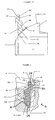
- a ball valve assembly is generally indicated by the reference numeral 10.
- the valve assembly 10 in this exemplary embodiment is a floating ball design in which the ball is captured between two flexible seat rings, such as, for example, the ball valve design illustrated and described in the '165 patent.
- Most of the elements of the ball valve assembly 10 are conventional and may be, for example, the same as described in the '165 patent and the details thereof need not be repeated herein.
- the present invention is directed to improvements in the design of specific elements such as the seat ring and associated seals, and these modifications will be described in detail herein. Those skilled in the art will appreciate, however, that the improvements described herein will have application to other ball valve designs and are not limited to use with a ball valve as described in the '165 patent.
- the ball valve assembly 10 includes a ball valve body A with a ball valve member B disposed in a central passageway 12 in the valve body A.
- the ball member B is mounted for selective rotation between a valve open position as illustrated in the various views, and a valve closed position (not shown).
- a pair of seat assemblies C and D are provided in the central passageway 12 on opposite sides of the ball member B.
- the ball member B and the seat assemblies C and D are enclosed within the valve ball body A by a pair of opposed end fittings E and F.
- the end fittings E and F are mounted to the valve body A by any convenient device, in this example a number of mounting bolts G.
- a stem assembly I and actuating handle assembly H are used to actuate the valve 10.
- the stem assembly I is connected to the handle assembly H and also helps support the ball member B in the valve body A, the details of which are fully described in the '165 patent.
- the ball member B is supported in the passageway 12 such that the ball member B can shift axially (referenced to the longitudinal axis of fluid flow through the ball B) within the passageway 12 when the valve 10 is under pressure, such as, for example, when the valve is closed.
- the valve 10 may be manually actuated with the handle H, or alternatively the valve 10 may have an actuator mounted thereon as is known.
- Fig. 2 illustrates the ball member B and seat assemblies C and D of Fig. 1 in an enlarged view.
- the stem assembly I has been omitted for clarity and ease of illustration of the seat assemblies C and D.
- the central passageway 12 is generally cylindrical and is just slightly greater in diameter than the ball member B.
- the ball member B includes a fluid flow opening 14 that in the valve open position such as illustrated in Fig. 2 is aligned with fluid inlet and outlet ports in the end fittings E and F.
- Each seat assembly includes three basic components, namely a seat ring 16, a flange seal 18 and a resilient force generating member 20 such as, for example, a disc spring 20. Any suitable element may be used to apply the energized load against the seat ring 16. A support or reinforcing ring 22 may also be used.
- the disc spring 20 and the support ring 22 are substantially the same in structure and function as described in the '165 patent and that description is not repeated herein. In some applications, a stronger disc spring may be used to assure that the seat ring 16 sealingly engages the ball member B after temperature and/or pressure cycling.
- the disc spring 20 operates to bias or force a seal surface 24 (see Fig. 3) of the associated the seat ring 16 against the outer surface 26 of the ball member B. As will be further explained hereinafter, in the illustrated embodiment, the disc spring 20 also applies an energized axial load against the seat flange 30.
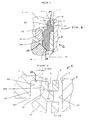
- Figs. 4 and 5 illustrate a further enlarged view of the seat assembly arrangement C in accordance with this first embodiment of the invention.
- Fig. 5 illustrates the components in a fully assembled condition
- Fig. 4 illustrates the components with the valve nearly fully assembled but without a full axial compression of the seat assembly C.
- the end fitting F provides an inner shoulder 28 that faces the disc spring 20, an annular flange 30 of the seat ring 16 and the flange seal 18. The end fitting F thus captures and axially compresses the seat assembly C in the central passageway 12 and in sealing engagement with the ball member B.
- the seat ring 16 is a generally disc shaped or ring-like member having a radially inward annular sealing surface 24 in contact with the ball member outer surface 26.
- the seat ring 16 further includes a radially and axially extending annular outer circumferential flange or tab 30.
- the flange 30 is closely received in a counterbore 34 formed in the valve body A.
- the counterbore 34 forms a shoulder 36 that supports a first axial face 38 of the radial flange 30.
- An axially extending portion 32 of the flange 30 faces and abuts the end fitting shoulder 28 without axial compression of the flange 30.
- there be a gap of about 0.0 -0.4 in. between the face of the extension 32 and the fitting shoulder 28 so that no appreciable axial compression is applied directly to the flange 30 by the shoulder 28, yet the flange 30 is fully captured and constrained against axial displacement as will be described herein.
- the flange 30 is also formed with a circumferentially continuous notch or recess 40 (Fig. 6).
- the flange seal 18 is disposed within the flange recess 40.
- the resilient seal 18 is typically oversized so as to extend axially beyond the flange extension 32.
- the disc spring 20 partially extends axially beyond the extension 32 so that the disc spring 20 and the resilient seal 18 are axially compressed during assembly without an axial compression being directly applied to the flange 30 by the fitting shoulder 28.
- all of the axial compressive load applied to the flange 30 is a resilient dynamic load applied by the disc spring 20 and the resilient seal 18, with substantially no static load applied to the flange 30.
- each flange 30 is disposed in a flange groove defined by the surfaces 28, 34 and 36 of the assembled valve (see Fig. 5).
- the flange 30 is axially captured between the fitting shoulder 28 and the counterbore shoulder 36 with a resilient load applied thereto by the disc spring 20 and the resilient seal 18.
- the flange seal 18 is axially compressed between the end fitting shoulder 28 and a second axial face 42 of the flange 30.
- the seat rings 16 are preferably made of a stiffer and harder plastic material such as PEEK
- the flange seal 18 is preferably made of a resilient material that produces an energized seal between the flange 30 and the valve body A and end fittings E and F.
- the flange seal 18 may be made of any suitable resilient energized material, and preferably is made of an elastomeric material or a stiffer seal material with spring-like characteristics such as flexible graphite (e.g. Grafoil TM). Other suitable materials include but are not limited to metal o-rings, C-seals and so forth.
- the seal 18 is a GrafoilTM type seal.
- the terms "energized” and “resilient” are used interchangeably to convey the concept that the seal 18 provides an energized body seal and an energized axial load against the flange 30.
- the seal 18 need only be flexible or resilient enough to provide a resilient energized seal that withstands temperature cycling of the valve 10. Thus a fairly stiff material such as flexible graphite for example is suitable for the seal 18.
- the seat ring 16 has been thinned in its axial dimension generally between its outer diameter and its inner diameter by removing material.
- the seat 16 includes a notch 100.
- This notch 100 is circumferentially continuous though it need not be.
- the seat 16 is configured so as to increase its flexibility in the axial direction. In other words, by thinning or contouring the central body of the seat 16, the inner portion of the seat 16 that forms the seal surface 24 is urged into sealing contact with the outer surface 26 of the ball member B by the disc spring 20. When the valve 10 is under low pressure, this sealing contact is preferably but not necessarily a near line contact seal with the ball surface 26.
- the new seat ring configuration is particularly useful for making the seat ring 16 out of a relatively harder and stiffer thermoplastic material such as polyetheretherketone (PEEK), as compared to the seat ring design of the '165 patent that is made of a relatively softer plastic material such as PTFE (TeflonTM).
- PEEK polyetheretherketone
- Other materials besides PEEK may be used including but not limited to polyamide-imide (e.g. TorlonTM), polyimide (e.g. VespelTM), poly vinylidene-fluoride (e.g. KynarTM) and polychlorotrifluoroethylene (e.g. Kel-FTM) and reinforced PTFE (for example, glass or carbon filled PTFE).
- the seat ring material have a Young's Modulus property or stiffness characteristic that is higher than that of a softer material such as PTFE. More preferably, the seat material has a Young's Modulus that is about ten times higher than the Young's Modulus of a softer material such as PTFE. Still more preferably, the seat material has a Young's Modulus of about 400,000 to 600,000 psi.
- PEEK increases the high temperature performance for the ball valve 10 as compared to the use of a material such as PTFE.
- PEEK is a substantially harder and stiffer material compared to PTFE, and therefore the energized flange seal 18 is provided to assure that an adequate valve body seal is maintained after temperature cycling.
- the captured and axially compressed flange 30 restricts and substantially prevents free axial sliding movement of the seat ring 16 in response to pressure across the valve ports. Furthermore, the seat ring seal surface 24 engages the ball surface 26 under force of the disc spring 20.
- the disc spring 20 imparts maximum axial force to the seat ring 16 from the radially innermost edge 70 of the seat ring sealing surface 24.
- the spring 20 force exerted on the seat 16 to provide the ball seal decreases radially outward.
- the ball diameter, seat ring and spring are appropriately sized so that as the valve is assembled the seat ring 16 is flexed to produce an excellent sealing contact seal between the seat 16 and the ball B.
- the clamped flange 30 of the present invention provides a rigid pivot region or pivot point about which flexure of the seat ring 16 can occur while limiting the axial displacement of the seat ring 16 under pressure.
- the radially inner portion of the seat 16 that forms the seal surface 24 is flexible from the pivot point in a cantilever type fashion. This flexibility is enhanced by the removal of seat material from the notch 100.
- the disc spring 20 can more effectively exert a force against the seat ring 16 to assure good sealing contact between the seat ring seal surface 24 and the ball surface 26. This is particularly beneficial when a harder and stiffer plastic material such as PEEK is used for the seat ring.
- the seat assembly D is restricted from axial displacement (though there may still be some axial flexing) when the valve 10 is under pressure.
- This restricted axial movement substantially reduces or eliminates excessive loads and stresses from being applied to the downstream seat 16.
- the seats 16 will not plastically deform particularly under increased temperature. This assures that when the pressure and or temperature return to ambient, the disc springs 20 will be able to urge the seats 16 into excellent sealing condition with the ball B.
- the new seat assemblies C and D along with the use of harder materials (PEEK in this embodiment) significantly improve the performance of the valve under repeated temperature and pressure cycling.
- the cantilever effect of the clamped flange 30 along with the flexible geometry of the seat 16 provides additional performance improvements.
- the stiffness of the cantilever design increases the force of the seat ring 16 on the ball B to generate contact pressure between the seal surface 24 and the ball surface 26 that is greater than the force generated by the disc springs 20 alone.
- the cantilever configuration controls orientation of the spherical sealing surface 24 on the seat 16.
- the cantilever function allows the seat 16 to flex under high pressure and/or temperature to give full face contact between the ball B and the downstream seat. This distributes the load on the downstream seat and reduces deformation.
- the downstream seat 16 pivots back (in cantilever fashion) to its original shape under force of the spring 20 and re-establishes its original sealing contact with the ball B. This enhances the capability of the seats 16 to seal against the ball B under low pressure after thermal cycling. Additionally, since the cantilever action is fixed between the body and the flange at a clamped pivot point, the upstream seat 16 bends instead of sliding downstream in response to upstream pressure. Thus, some of the load of the upstream seat created by pressure on the back face of the upstream seat is transferred to the valve body instead of the ball B. This results in less load being transferred from the ball to the downstream seat.
- the clamped flange 30 reduces the effective diameter of the upstream seat under pressure, thus reducing the force transmitted through the ball to the downstream seat.
- the support rings 22 also take up some of the load from the upstream seat under pressure by reducing the effective diameter of the seat 16 when it pivots under pressure, thereby further reducing the load that would otherwise be transferred to the downstream seat through the ball.
- the seal 18 is isolated from those portions of the seat ring 16 that tend to flex, bend and move during temperature and pressure cycling.
- the seat 16 is stationary vis-à-vis the resilient seal 18 even when the main portion of the seat 16 is moving or flexing due to the cantilever design.
- the flange seal 18 cannot extrude into these gaps and become damaged.
- the flange seal 18 is intended to form a primary and outer body seal at two faces, X and Z, and to reduce the effects of higher temperature cycling on the seat 16.
- the axial compression of the flange seal 18 between the shoulder 28 and the flange second axial face 42 assures a good body seal along the radially extending faces X and Z to prevent fluid under pressure from leaking.
- the resilient seal 18 may also form a secondary or backup seal at the surface Y, particularly when the seal 18 is made of a stiffer material such as flexible graphite.
- the secondary peripheral seal Y of the present invention may be advantageous when the seat ring 16 is made of a harder and stiffer material such as PEEK.
- the o-ring designated 82 in the '165 patent would have to provide a radially inward seal at the outer circumferential surface of the seat ring.
- This seal location was not required in the '165 patent because the seat ring was made of PTFE which provided an adequate seal at the flanges 140, 142.
- trying to seal along the outer circumferential surface of the '165 seat ring is difficult because system pressure tends to push the O-ring radially away from the seat ring.
- the seat flange 30 includes a generally axial inward face 200 that is axially compressed against the counterbore 36 when the valve 10 is fully assembled.
- the inward face 200 forms an inner body seal with the surface BB of the counterbore 34 radial shoulder 36.
- This seal is excellent at cryogenic temperatures and lower pressures.
- we have found that the seal performance is substantially enhanced by including a radial taper angle ⁇ to the face 200. This taper causes a corner 202 of the valve body A to initially be axially compressed into the seat 16 as the valve is assembled.
- the flange 30 pivots somewhat about the body corner 202 and abuts and is compressed against the surface BB.
- the flange 30 thus is somewhat bent about the corner 202 to form an increased stress or compression seal between the corner 202 and the seat 16. This produces an excellent primary inner body seal even when the valve is subjected to temperature and pressure cycles.
- the corner 202 seal reduces the seal strength required along the surface Y by the flange seal 18.
- the flange seal 18 is highly resilient such as an elastomer, fluid pressure from fluid getting past the surface BB could in some cases push the seal 18 away from the surface Y. This effect would be less pronounced when the flange seal 18 is made of a stiffer material, such as a flexible graphite material. Nonetheless, even when such a stiffer energized seal 18 is used, it is preferred, although not required in all applications, to form a primary seal at the corner 202 This seal significantly improves the seal performance under pressure.
- the corner 202 seal is also an energized seal due to the energized force applied to the flange 30 by the disc spring 20 and the resilient seal 18.
- the disc spring 20 may be omitted (provided there is sufficient compression of the seat 16 against the ball B) if the flange seal 18 applies a sufficient energized axial load of the flange 30 against the corner 202.
- the primary inner body seal does not necessarily have to be produced at the corner 202, but rather may be formed anywhere along the surface BB that defines the counterbore 34.
- This seal can be effected by simply applying sufficient axial compression of the flange 30 against the counterbore 34 surface, either using the resilient seal 18, the disc spring 20 or both.
- a stiffer seal 18 such as flexible graphite, may be used in some applications to effectively seal at all three surfaces X, Y and Z, thus eliminating the need to form the corner 202 seal or a primary seal along the counterbore 34 surface BB.
- These alternative embodiments thus may eliminate the need for the tapered surface 200 of the flange 30.
- the new seat seal assembly 16, 18 is effective to seal against fluid pressure from two directions, namely inner fluid pressure that reaches the corner 202 and outer fluid pressure at the shoulder 28.
- This is accomplished in the illustrated embodiment by the inner body seal at the corner 202 and the outer body seal effected by the energized seal 18.
- the energized flange seal 18 provides excellent seals at the surfaces X and Z even with high temperature cycling of the valve, and the corner 202 seal provides an excellent seal with the valve 10 under pressure.
- the energized resilient flange seal 18 also may improve the seal performance under pressure because fluid pressure along the surface 28 will tend to force the flange seal 18 radially against the surface Y as a secondary seal for the corner 202 seal.
- the seat ring 16 includes an inward facing seal surface 24 that contacts the outer surface 26 of the ball member B.
- the ball engaging surface 24 is generally spherical in shape with a radius of curvature in the unassembled state that is greater than the radius of curvature of the ball member B outer surface 26.
- the shape of the surface 24 is similar to the seat ring seal surface 136 of the '165 patent.
- the seat ring 16 is designed to exhibit a spring-like elasticity to exert a sealing force against the ball surface 26. This is accomplished by having the seat surface 24 distort or flex axially outward when the seat ring is axially compressed between the ball surface 26 and the disc spring 20 during assembly.
- the seat ring 16 contacts the ball surface 26 along the inner rim 70 of the seal surface 24.
- the rim 70 is defined by the inner axial edge of a cylindrical surface 72 that forms a fluid passage through the seat ring. This fluid passage circumferentially surrounds the flow opening 14 in the ball member.
Landscapes
- Engineering & Computer Science (AREA)
- General Engineering & Computer Science (AREA)
- Mechanical Engineering (AREA)
- Taps Or Cocks (AREA)
- Check Valves (AREA)
Abstract
Description
Claims (24)
- A ball valve comprising:a body (A) having a passageway (12) extending there through;a ball member (B) disposed in said passageway (12) and mounted for selective rotation between valve open and valve closed positions to control fluid flow through the valve;a pair of seat rings (16) in said passageway (12) on opposite sides of said ball (B);each seat ring (16) having a first sealing surface (24) in contact with an outer surface of said ball (16); characterized by:a pair of flange grooves (28, 34, 36) in said body (A) on opposite sides of said ball (B), each said flange groove (28, 34, 36) extending radially from said passageway (12);each seat ring (16) having a radially extending annular flange (30) received in an associated one of said flange grooves (28,34,36); anda pair of annular flange seals (18) each disposed in a respective one of said flange grooves to form a respective body seal.
- The valve of claim 1 wherein said flange seal comprises an elastomeric material.
- The valve of claim 1 wherein said flange seal comprises an o-ring.
- The valve of claim 1 wherein said flange seal comprises an energized resilient seal with spring-like characteristics.
- The valve of claim 1 wherein said seat rings comprise a relatively harder and stiffer thermoplastic material compared to PTFE.
- The valve of claim 5 wherein said seat rings comprise PEEK.
- The valve of claim 1 wherein each said flange and flange seal is axially compressed in said flange groove.
- The valve of claim 7 wherein each said flange is axially compressed to form a seal between said flange and said body.
- The valve of claim 7 wherein each said flange is radially tapered so that under axial compression said flange forms a primary seal at a corner in said flange groove.
- The valve of claim 9 wherein each said flange seal provides a secondary seal relative to said primary seal.
- The valve of claim 10 wherein each said flange seal forms axial seals against said flange and said valve body.
- The valve of claim 1 wherein said seat ring flanges are axially compressed in said flange grooves and limit axial movement of said seat rings when the valve is under pressure.
- The valve of claim 12 wherein each said flange seal is disposed in a recess of a respective flange and separated from said passageway by said seat ring flange, said flange seal being stationary independent of said axial movement of said seat rings.
- The valve of claim 13 wherein each said seat ring flange comprises a circumferential recess, said respective flange seal being disposed in said flange recess.
- The valve of claim 14 wherein said circumferential flange recess is formed along an outer perimeter of said flange; and wherein said flange seal has an axial dimension greater than an axial dimension of said recess so that said flange seal is axially compressed when the valve is assembled to apply an energized load against said seat ring flange.
- The valve of claim 1 wherein each said seat flange seal comprises flexible graphite.
- A ball valve of the type comprising a rotatable ball member (B) disposed in a fluid passageway (12) of a valve body (A) and a pair of seat rings (16) each having a central main body that is respectively compressed against opposite sides of the ball member (B), characterised by:each seat ring (16) comprising a flange (30) that extends radially from said main body; and a flange seal (18) comprising a resilient material that is axially compressed with said flange (18) to form an energized body seal.
- The valve of claim 17 further comprising a resilient force applying member that applies an axial load against said flange to form a second energized body seal.
- The valve of claim 18 wherein each flange is bent around a corner of said valve body to form a high compression inner body seal.
- The valve of claim 19 wherein said flange seal provides an outer body seal.
- The valve of claim 17 wherein said flange seal comprises a material that is different from a material that forms said flange.
- The valve of claim 17 wherein said flange seal comprises an elastomer.
- The valve of claim 17 wherein said flange seal comprises flexible graphite.
- The valve of claim 17 wherein said seat comprises a material that is relatively stiffer and harder compared to PTFE.
Priority Applications (1)
| Application Number | Priority Date | Filing Date | Title |
|---|---|---|---|
| EP05023368A EP1643173B1 (en) | 1999-11-23 | 2000-11-21 | Ball valve seat seal |
Applications Claiming Priority (3)
| Application Number | Priority Date | Filing Date | Title |
|---|---|---|---|
| US16717399P | 1999-11-23 | 1999-11-23 | |
| US167173P | 1999-11-23 | ||
| PCT/US2000/032046 WO2001038761A1 (en) | 1999-11-23 | 2000-11-21 | Ball valve seat seal |
Related Child Applications (1)
| Application Number | Title | Priority Date | Filing Date |
|---|---|---|---|
| EP05023368A Division EP1643173B1 (en) | 1999-11-23 | 2000-11-21 | Ball valve seat seal |
Publications (2)
| Publication Number | Publication Date |
|---|---|
| EP1232350A1 EP1232350A1 (en) | 2002-08-21 |
| EP1232350B1 true EP1232350B1 (en) | 2005-11-02 |
Family
ID=22606255
Family Applications (1)
| Application Number | Title | Priority Date | Filing Date |
|---|---|---|---|
| EP00980653A Expired - Lifetime EP1232350B1 (en) | 1999-11-23 | 2000-11-21 | Ball valve seat seal |
Country Status (8)
| Country | Link |
|---|---|
| EP (1) | EP1232350B1 (en) |
| JP (1) | JP2003515078A (en) |
| CN (1) | CN1214200C (en) |
| AT (2) | ATE352738T1 (en) |
| AU (1) | AU1788501A (en) |
| DE (2) | DE60023733T2 (en) |
| TW (1) | TW565668B (en) |
| WO (1) | WO2001038761A1 (en) |
Cited By (1)
| Publication number | Priority date | Publication date | Assignee | Title |
|---|---|---|---|---|
| EP3628899A1 (en) * | 2018-09-26 | 2020-04-01 | Johnson Electric International AG | Valve |
Families Citing this family (27)
| Publication number | Priority date | Publication date | Assignee | Title |
|---|---|---|---|---|
| GB0128231D0 (en) * | 2001-11-24 | 2002-01-16 | British Nuclear Fuels Plc | Improvements in and relating to ball valve assemblies |
| US7644840B2 (en) * | 2005-02-04 | 2010-01-12 | Fluid Management Operations Llc | Valve assembly for viscous fluid dispensers |
| US7559531B2 (en) | 2006-11-30 | 2009-07-14 | Tac, Llc | Low torque ball valve with dynamic sealing |
| JP4980095B2 (en) * | 2007-02-21 | 2012-07-18 | 株式会社テイエルブイ | Float type steam trap |
| ITMI20070093U1 (en) | 2007-03-20 | 2008-09-21 | Bonetti Cesare Spa | BALL VALVE WITH DETACHABLE REMOVAL MEANS OF AXIAL SEAL GASKET |
| JP2009014152A (en) | 2007-07-06 | 2009-01-22 | Sony Corp | Bearing unit, motor having bearing unit, and electronic device |
| US8365755B2 (en) | 2007-08-23 | 2013-02-05 | Norgren Limited | Ball valve isolator |
| US8413684B2 (en) | 2009-09-16 | 2013-04-09 | Schneider Electric Buildings, Llc | Ball valve with anti-rotational pressure plate |
| US8646752B2 (en) | 2011-02-24 | 2014-02-11 | Virgo Engineers, Inc. | Ball valve having multiple moveable seats |
| EP2667068B1 (en) | 2012-05-23 | 2018-02-14 | Cameron International Corporation | Valve with contoured bore to deflect particles |
| EP2667067A1 (en) * | 2012-05-23 | 2013-11-27 | Cameron International Corporation | Valve with adaptive facial sealing ring |
| EP2667066B1 (en) | 2012-05-23 | 2018-01-17 | Cameron International Corporation | Protective facial sealing arrangement |
| JP5850876B2 (en) * | 2013-04-12 | 2016-02-03 | 株式会社鷺宮製作所 | Ball valve |
| WO2016006175A1 (en) * | 2014-07-07 | 2016-01-14 | 株式会社デンソー | Valve device |
| JP6432433B2 (en) * | 2014-07-07 | 2018-12-05 | 株式会社デンソー | Valve device |
| DE202015100400U1 (en) | 2015-01-28 | 2016-05-02 | Woco Industrietechnik Gmbh | Sealing arrangement and valve |
| JP6490021B2 (en) * | 2015-04-06 | 2019-03-27 | 株式会社Soken | Valve device |
| CN106090281B (en) * | 2015-11-19 | 2018-12-18 | 舍弗勒技术股份两合公司 | Ball valve and sealing member for ball valve |
| EP3695145B1 (en) * | 2017-10-10 | 2024-03-06 | Cameron Technologies Limited | Contoured integrated seat for ball valve |
| CN110043681A (en) * | 2018-01-17 | 2019-07-23 | 青岛海融知识产权代理有限公司 | A kind of high-performance ball valve |
| DE102018117240A1 (en) | 2018-07-17 | 2020-01-23 | Illinois Tool Works Inc. | Coolant valve for a vehicle |
| PL3824207T3 (en) * | 2018-07-19 | 2024-06-03 | Gea Tuchenhagen Gmbh | Lifting valve and seal |
| CN110953371A (en) * | 2019-12-27 | 2020-04-03 | 宜宾三江机械有限责任公司 | One-way sealing ball valve |
| WO2021137995A1 (en) * | 2019-12-31 | 2021-07-08 | Saint-Gobain Performance Plastics Corporation | Design for a seat insert in a ball valve for cryogenic applications |
| CN113514198A (en) * | 2021-07-30 | 2021-10-19 | 重庆川仪调节阀有限公司 | A kind of experimental device and test method for sealing performance of flexible graphite sealing ring |
| IT202100030335A1 (en) * | 2021-11-30 | 2023-05-30 | Buti Res S R L | FIXED SEAT SHUT-OFF VALVE AND ASSEMBLY PROCEDURE. |
| CN117759747A (en) * | 2022-09-19 | 2024-03-26 | 浙江三花汽车零部件有限公司 | Control valve |
Family Cites Families (7)
| Publication number | Priority date | Publication date | Assignee | Title |
|---|---|---|---|---|
| GB1093711A (en) * | 1964-02-25 | 1967-12-06 | Saunders Valve Co Ltd | Fluid controlling valves |
| US4111393A (en) * | 1977-07-20 | 1978-09-05 | Acf Industries, Incorporated | Ball valve seat assembly having a removably mounted face seal insert |
| US4258900A (en) * | 1979-05-21 | 1981-03-31 | Kamyr Valves, Inc. | Structure maintaining seats against ball valves |
| CA1133877A (en) * | 1979-12-12 | 1982-10-19 | Ulrich H. Koch | Ball valve and seat assembly |
| US4410165A (en) | 1982-02-16 | 1983-10-18 | Whitey Co. | Ball valve and seat assembly |
| US4602762A (en) | 1982-02-16 | 1986-07-29 | Whitey Co. | Ball valve and seat assembly |
| GB2187264A (en) * | 1986-02-12 | 1987-09-03 | Whitey Co | Rotary valves |
-
2000
- 2000-11-21 CN CN00818609.XA patent/CN1214200C/en not_active Expired - Fee Related
- 2000-11-21 AT AT05023368T patent/ATE352738T1/en not_active IP Right Cessation
- 2000-11-21 AT AT00980653T patent/ATE308699T1/en not_active IP Right Cessation
- 2000-11-21 JP JP2001540279A patent/JP2003515078A/en not_active Withdrawn
- 2000-11-21 AU AU17885/01A patent/AU1788501A/en not_active Abandoned
- 2000-11-21 EP EP00980653A patent/EP1232350B1/en not_active Expired - Lifetime
- 2000-11-21 WO PCT/US2000/032046 patent/WO2001038761A1/en not_active Ceased
- 2000-11-21 DE DE60023733T patent/DE60023733T2/en not_active Expired - Fee Related
- 2000-11-21 DE DE60033206T patent/DE60033206T2/en not_active Expired - Fee Related
-
2001
- 2001-01-29 TW TW089124895A patent/TW565668B/en not_active IP Right Cessation
Cited By (1)
| Publication number | Priority date | Publication date | Assignee | Title |
|---|---|---|---|---|
| EP3628899A1 (en) * | 2018-09-26 | 2020-04-01 | Johnson Electric International AG | Valve |
Also Published As
| Publication number | Publication date |
|---|---|
| TW565668B (en) | 2003-12-11 |
| CN1214200C (en) | 2005-08-10 |
| DE60033206D1 (en) | 2007-03-15 |
| JP2003515078A (en) | 2003-04-22 |
| ATE308699T1 (en) | 2005-11-15 |
| DE60023733T2 (en) | 2006-07-27 |
| ATE352738T1 (en) | 2007-02-15 |
| DE60023733D1 (en) | 2005-12-08 |
| DE60033206T2 (en) | 2007-11-15 |
| CN1425112A (en) | 2003-06-18 |
| AU1788501A (en) | 2001-06-04 |
| WO2001038761A1 (en) | 2001-05-31 |
| EP1232350A1 (en) | 2002-08-21 |
Similar Documents
| Publication | Publication Date | Title |
|---|---|---|
| US6695285B1 (en) | Ball valve seat seal | |
| EP1232350A1 (en) | Ball valve seat seal | |
| US3894718A (en) | Ball valve | |
| US5893389A (en) | Metal seals for check valves | |
| US20100200791A1 (en) | Valve Having High Pressure and Low Pressure Seals | |
| KR20070032821A (en) | Ball valve seat structure | |
| US4293116A (en) | Metallic seat assembly for valves | |
| JPS645185B2 (en) | ||
| JPH0384268A (en) | Rotary valve with seal | |
| CA1138402A (en) | Cryogenic valve seal | |
| CA1133877A (en) | Ball valve and seat assembly | |
| US7478816B2 (en) | Seal stiffener | |
| TW202447116A (en) | Diaphragm valve with actuator bearing element | |
| JPH0542586B2 (en) | ||
| EP0013265B1 (en) | Seat assembly for high-temperature valves and use in butterfly valves | |
| EP1643173B1 (en) | Ball valve seat seal | |
| US4408771A (en) | High pressure sealing connection with metal seal | |
| JP3863563B2 (en) | Valve device | |
| JPH07117163B2 (en) | Seal liner | |
| JPS62266276A (en) | Ball valve | |
| EP0047147B1 (en) | Improvements in or relating to fluid control valves | |
| JPH0914463A (en) | Sheet ring of butterfly valve | |
| EP4437253A1 (en) | Sealing system for mechanical members |
Legal Events
| Date | Code | Title | Description |
|---|---|---|---|
| PUAI | Public reference made under article 153(3) epc to a published international application that has entered the european phase |
Free format text: ORIGINAL CODE: 0009012 |
|
| 17P | Request for examination filed |
Effective date: 20020524 |
|
| AK | Designated contracting states |
Kind code of ref document: A1 Designated state(s): AT BE CH CY DE DK ES FI FR GB GR IE IT LI LU MC NL PT SE TR |
|
| AX | Request for extension of the european patent |
Free format text: AL;LT;LV;MK;RO;SI |
|
| 17Q | First examination report despatched |
Effective date: 20041130 |
|
| GRAP | Despatch of communication of intention to grant a patent |
Free format text: ORIGINAL CODE: EPIDOSNIGR1 |
|
| GRAS | Grant fee paid |
Free format text: ORIGINAL CODE: EPIDOSNIGR3 |
|
| GRAA | (expected) grant |
Free format text: ORIGINAL CODE: 0009210 |
|
| AK | Designated contracting states |
Kind code of ref document: B1 Designated state(s): AT BE CH CY DE DK ES FI FR GB GR IE IT LI LU MC NL PT SE TR |
|
| PG25 | Lapsed in a contracting state [announced via postgrant information from national office to epo] |
Ref country code: IT Free format text: LAPSE BECAUSE OF FAILURE TO SUBMIT A TRANSLATION OF THE DESCRIPTION OR TO PAY THE FEE WITHIN THE PRESCRIBED TIME-LIMIT;WARNING: LAPSES OF ITALIAN PATENTS WITH EFFECTIVE DATE BEFORE 2007 MAY HAVE OCCURRED AT ANY TIME BEFORE 2007. THE CORRECT EFFECTIVE DATE MAY BE DIFFERENT FROM THE ONE RECORDED. Effective date: 20051102 Ref country code: NL Free format text: LAPSE BECAUSE OF FAILURE TO SUBMIT A TRANSLATION OF THE DESCRIPTION OR TO PAY THE FEE WITHIN THE PRESCRIBED TIME-LIMIT Effective date: 20051102 Ref country code: BE Free format text: LAPSE BECAUSE OF FAILURE TO SUBMIT A TRANSLATION OF THE DESCRIPTION OR TO PAY THE FEE WITHIN THE PRESCRIBED TIME-LIMIT Effective date: 20051102 Ref country code: AT Free format text: LAPSE BECAUSE OF FAILURE TO SUBMIT A TRANSLATION OF THE DESCRIPTION OR TO PAY THE FEE WITHIN THE PRESCRIBED TIME-LIMIT Effective date: 20051102 Ref country code: LI Free format text: LAPSE BECAUSE OF FAILURE TO SUBMIT A TRANSLATION OF THE DESCRIPTION OR TO PAY THE FEE WITHIN THE PRESCRIBED TIME-LIMIT Effective date: 20051102 Ref country code: CH Free format text: LAPSE BECAUSE OF FAILURE TO SUBMIT A TRANSLATION OF THE DESCRIPTION OR TO PAY THE FEE WITHIN THE PRESCRIBED TIME-LIMIT Effective date: 20051102 Ref country code: FI Free format text: LAPSE BECAUSE OF FAILURE TO SUBMIT A TRANSLATION OF THE DESCRIPTION OR TO PAY THE FEE WITHIN THE PRESCRIBED TIME-LIMIT Effective date: 20051102 Ref country code: TR Free format text: LAPSE BECAUSE OF FAILURE TO SUBMIT A TRANSLATION OF THE DESCRIPTION OR TO PAY THE FEE WITHIN THE PRESCRIBED TIME-LIMIT Effective date: 20051102 |
|
| REG | Reference to a national code |
Ref country code: GB Ref legal event code: FG4D |
|
| REG | Reference to a national code |
Ref country code: CH Ref legal event code: EP |
|
| PG25 | Lapsed in a contracting state [announced via postgrant information from national office to epo] |
Ref country code: CY Free format text: LAPSE BECAUSE OF FAILURE TO SUBMIT A TRANSLATION OF THE DESCRIPTION OR TO PAY THE FEE WITHIN THE PRESCRIBED TIME-LIMIT Effective date: 20051121 Ref country code: IE Free format text: LAPSE BECAUSE OF NON-PAYMENT OF DUE FEES Effective date: 20051121 |
|
| PG25 | Lapsed in a contracting state [announced via postgrant information from national office to epo] |
Ref country code: MC Free format text: LAPSE BECAUSE OF NON-PAYMENT OF DUE FEES Effective date: 20051130 |
|
| REF | Corresponds to: |
Ref document number: 60023733 Country of ref document: DE Date of ref document: 20051208 Kind code of ref document: P |
|
| PG25 | Lapsed in a contracting state [announced via postgrant information from national office to epo] |
Ref country code: LU Free format text: LAPSE BECAUSE OF NON-PAYMENT OF DUE FEES Effective date: 20060102 |
|
| PG25 | Lapsed in a contracting state [announced via postgrant information from national office to epo] |
Ref country code: GR Free format text: LAPSE BECAUSE OF FAILURE TO SUBMIT A TRANSLATION OF THE DESCRIPTION OR TO PAY THE FEE WITHIN THE PRESCRIBED TIME-LIMIT Effective date: 20060202 Ref country code: GB Free format text: LAPSE BECAUSE OF NON-PAYMENT OF DUE FEES Effective date: 20060202 Ref country code: SE Free format text: LAPSE BECAUSE OF FAILURE TO SUBMIT A TRANSLATION OF THE DESCRIPTION OR TO PAY THE FEE WITHIN THE PRESCRIBED TIME-LIMIT Effective date: 20060202 Ref country code: DK Free format text: LAPSE BECAUSE OF FAILURE TO SUBMIT A TRANSLATION OF THE DESCRIPTION OR TO PAY THE FEE WITHIN THE PRESCRIBED TIME-LIMIT Effective date: 20060202 |
|
| PG25 | Lapsed in a contracting state [announced via postgrant information from national office to epo] |
Ref country code: ES Free format text: LAPSE BECAUSE OF FAILURE TO SUBMIT A TRANSLATION OF THE DESCRIPTION OR TO PAY THE FEE WITHIN THE PRESCRIBED TIME-LIMIT Effective date: 20060213 |
|
| PG25 | Lapsed in a contracting state [announced via postgrant information from national office to epo] |
Ref country code: PT Free format text: LAPSE BECAUSE OF FAILURE TO SUBMIT A TRANSLATION OF THE DESCRIPTION OR TO PAY THE FEE WITHIN THE PRESCRIBED TIME-LIMIT Effective date: 20060403 |
|
| NLV1 | Nl: lapsed or annulled due to failure to fulfill the requirements of art. 29p and 29m of the patents act | ||
| REG | Reference to a national code |
Ref country code: CH Ref legal event code: PL |
|
| REG | Reference to a national code |
Ref country code: IE Ref legal event code: MM4A |
|
| PLBE | No opposition filed within time limit |
Free format text: ORIGINAL CODE: 0009261 |
|
| STAA | Information on the status of an ep patent application or granted ep patent |
Free format text: STATUS: NO OPPOSITION FILED WITHIN TIME LIMIT |
|
| 26N | No opposition filed |
Effective date: 20060803 |
|
| GBPC | Gb: european patent ceased through non-payment of renewal fee |
Effective date: 20060202 |
|
| EN | Fr: translation not filed | ||
| PG25 | Lapsed in a contracting state [announced via postgrant information from national office to epo] |
Ref country code: FR Free format text: LAPSE BECAUSE OF FAILURE TO SUBMIT A TRANSLATION OF THE DESCRIPTION OR TO PAY THE FEE WITHIN THE PRESCRIBED TIME-LIMIT Effective date: 20061222 |
|
| PG25 | Lapsed in a contracting state [announced via postgrant information from national office to epo] |
Ref country code: FR Free format text: LAPSE BECAUSE OF FAILURE TO SUBMIT A TRANSLATION OF THE DESCRIPTION OR TO PAY THE FEE WITHIN THE PRESCRIBED TIME-LIMIT Effective date: 20051130 |
|
| PG25 | Lapsed in a contracting state [announced via postgrant information from national office to epo] |
Ref country code: FR Free format text: LAPSE BECAUSE OF FAILURE TO SUBMIT A TRANSLATION OF THE DESCRIPTION OR TO PAY THE FEE WITHIN THE PRESCRIBED TIME-LIMIT Effective date: 20051102 |
|
| PGFP | Annual fee paid to national office [announced via postgrant information from national office to epo] |
Ref country code: DE Payment date: 20081223 Year of fee payment: 9 |
|
| PG25 | Lapsed in a contracting state [announced via postgrant information from national office to epo] |
Ref country code: DE Free format text: LAPSE BECAUSE OF NON-PAYMENT OF DUE FEES Effective date: 20100601 |