EP1231791A2 - Method and apparatus for synchronously reproducing audio and video data - Google Patents
Method and apparatus for synchronously reproducing audio and video data Download PDFInfo
- Publication number
- EP1231791A2 EP1231791A2 EP20010130506 EP01130506A EP1231791A2 EP 1231791 A2 EP1231791 A2 EP 1231791A2 EP 20010130506 EP20010130506 EP 20010130506 EP 01130506 A EP01130506 A EP 01130506A EP 1231791 A2 EP1231791 A2 EP 1231791A2
- Authority
- EP
- European Patent Office
- Prior art keywords
- audio
- decoder
- video data
- demultiplexer
- video
- Prior art date
- Legal status (The legal status is an assumption and is not a legal conclusion. Google has not performed a legal analysis and makes no representation as to the accuracy of the status listed.)
- Withdrawn
Links
Images


Classifications
-
- H—ELECTRICITY
- H04—ELECTRIC COMMUNICATION TECHNIQUE
- H04N—PICTORIAL COMMUNICATION, e.g. TELEVISION
- H04N21/00—Selective content distribution, e.g. interactive television or video on demand [VOD]
- H04N21/20—Servers specifically adapted for the distribution of content, e.g. VOD servers; Operations thereof
- H04N21/23—Processing of content or additional data; Elementary server operations; Server middleware
- H04N21/236—Assembling of a multiplex stream, e.g. transport stream, by combining a video stream with other content or additional data, e.g. inserting a URL [Uniform Resource Locator] into a video stream, multiplexing software data into a video stream; Remultiplexing of multiplex streams; Insertion of stuffing bits into the multiplex stream, e.g. to obtain a constant bit-rate; Assembling of a packetised elementary stream
- H04N21/2368—Multiplexing of audio and video streams
-
- H—ELECTRICITY
- H04—ELECTRIC COMMUNICATION TECHNIQUE
- H04N—PICTORIAL COMMUNICATION, e.g. TELEVISION
- H04N21/00—Selective content distribution, e.g. interactive television or video on demand [VOD]
- H04N21/40—Client devices specifically adapted for the reception of or interaction with content, e.g. set-top-box [STB]; Operations thereof
- H04N21/43—Processing of content or additional data, e.g. demultiplexing additional data from a digital video stream; Elementary client operations, e.g. monitoring of home network or synchronising decoder's clock; Client middleware
- H04N21/4302—Content synchronisation processes, e.g. decoder synchronisation
- H04N21/4305—Synchronising client clock from received content stream, e.g. locking decoder clock with encoder clock, extraction of the PCR packets
-
- H—ELECTRICITY
- H04—ELECTRIC COMMUNICATION TECHNIQUE
- H04N—PICTORIAL COMMUNICATION, e.g. TELEVISION
- H04N21/00—Selective content distribution, e.g. interactive television or video on demand [VOD]
- H04N21/40—Client devices specifically adapted for the reception of or interaction with content, e.g. set-top-box [STB]; Operations thereof
- H04N21/43—Processing of content or additional data, e.g. demultiplexing additional data from a digital video stream; Elementary client operations, e.g. monitoring of home network or synchronising decoder's clock; Client middleware
- H04N21/4302—Content synchronisation processes, e.g. decoder synchronisation
- H04N21/4307—Synchronising the rendering of multiple content streams or additional data on devices, e.g. synchronisation of audio on a mobile phone with the video output on the TV screen
- H04N21/43072—Synchronising the rendering of multiple content streams or additional data on devices, e.g. synchronisation of audio on a mobile phone with the video output on the TV screen of multiple content streams on the same device
-
- H—ELECTRICITY
- H04—ELECTRIC COMMUNICATION TECHNIQUE
- H04N—PICTORIAL COMMUNICATION, e.g. TELEVISION
- H04N21/00—Selective content distribution, e.g. interactive television or video on demand [VOD]
- H04N21/40—Client devices specifically adapted for the reception of or interaction with content, e.g. set-top-box [STB]; Operations thereof
- H04N21/43—Processing of content or additional data, e.g. demultiplexing additional data from a digital video stream; Elementary client operations, e.g. monitoring of home network or synchronising decoder's clock; Client middleware
- H04N21/433—Content storage operation, e.g. storage operation in response to a pause request, caching operations
- H04N21/4333—Processing operations in response to a pause request
-
- H—ELECTRICITY
- H04—ELECTRIC COMMUNICATION TECHNIQUE
- H04N—PICTORIAL COMMUNICATION, e.g. TELEVISION
- H04N21/00—Selective content distribution, e.g. interactive television or video on demand [VOD]
- H04N21/40—Client devices specifically adapted for the reception of or interaction with content, e.g. set-top-box [STB]; Operations thereof
- H04N21/43—Processing of content or additional data, e.g. demultiplexing additional data from a digital video stream; Elementary client operations, e.g. monitoring of home network or synchronising decoder's clock; Client middleware
- H04N21/434—Disassembling of a multiplex stream, e.g. demultiplexing audio and video streams, extraction of additional data from a video stream; Remultiplexing of multiplex streams; Extraction or processing of SI; Disassembling of packetised elementary stream
- H04N21/4341—Demultiplexing of audio and video streams
Definitions
- the present invention relates to an audio and video data synchronous reproduction apparatus and method for reproducing the multiplexed stream in which audio and video data are multiplexed together with time stamps.
- a method for reproducing the multiplexed stream (e.g. MP4 file) in which coded audio and video data is multiplexed together with time information is proposed.
- the multiplexed stream contains presentation time stamps each of which indicates, for example, the output timing of information for each audio and video frame.
- the time stamp is compared with the time indicated by an internal clock in a decoder, thereby determining the output timing of the decoder.
- An audio decoder decodes audio data separated from the multiplexed stream.
- the audio decoder compares a presentation time stamp attached to each decoded audio frame with the time (generally, a counter value, which is periodically incremented) indicated by the internal clock included therein. As a result of the comparison, if the presentation time stamp is identical to or exceeds the internal time, a signal is output to an output device such as a loudspeaker.
- a video decoder decodes video data. Also in this case, the video decoder compares the presentation time stamp attached to each decoded video frame with the time indicated by the internal clock included therein. As a result of the comparison, if the presentation time stamp is identical to or exceeds the indicated time of the internal clock, a signal is output to an output device such as an LCD (Liquid Crystal Display).
- LCD Liquid Crystal Display
- the time period required for decoding differs between the audio decoder and the video decoder. Accordingly, after a pause process finishes, the internal clocks of the audio and video decoders indicate different times (i.e. different counter values).
- the audio and video data may be reproduced at different points in time, since the audio and video decoders hold different internal times.
- the present invention has been developed in light of the above. There is a need to provide an audio and video data synchronous reproduction method and apparatus capable of executing appropriate reproduction, even after the release of a pause, without any problems resulting from different timings of audio and video data reproduction.
- an audio and video data synchronous reproduction apparatus for decoding, using an audio decoder, audio data separated by a demultiplexer from the multiplexed stream in which audio data, video data and a time stamp are multiplexed, and decoding, using a video decoder, video data separated by the demultiplexer from the multiplexed stream, the apparatus comprising:
- FIG. 1 is a schematic block illustrating an apparatus for synchronously reproducing audio and video data according to the embodiment.
- This apparatus comprises a demultiplexer 1 for receiving a multiplexed bitstream as an input signal, and separating the multiplexed bitstream into video data and audio data; an audio decoder 2 for receiving and decoding audio data separated by the demultiplexer 1; and a video decoder 3 for receiving and decoding video data separated by the demultiplexer 1.
- the demultiplexer 1, audio decoder 2 and video decoder 3 are provided with internal clocks 12, 21 and 32, respectively. Each internal clock increments its counter value every time each clock receives a clock signal pulse output from a pulse generator 4. Further, the output of the audio decoder 2 is temporarily stored in a buffer 22 and then input to a voice output device 5 such as a loudspeaker. The output of the video decoder 3 is temporarily stored in a buffer 32 and then input to a video output device 6 such as an LCD.
- the demultiplexer 1 includes a clock setting section 11.
- the clock setting section 11 is configured to receive a pause request signal generated from, for example, a CPU, and to set the time indicated by each internal clock (12, 21 and 31).
- FIG. 2 shows an example of a multiplexed bitstream.
- the multiplexed bitstream comprises a media identification ID, a presentation time stamp, a payload length and a payload.
- a video payload follows an audio payload.
- the media identification ID is used to identify whether the successive payload is an audio payload or a video payload. For example, the identification ID of 1 indicates an "audio" payload, and the identification ID of 2 indicates a "video" payload.
- the presentation time stamp indicates the presentation timing of each payload, using a numerical value in the unit of, for example, "ms”.
- the payload length indicates the length of a payload arranged next to the payload length field, in the unit of "bytes”. However, this embodiment is not limited to this format.
- the demultiplexer 1 subjects a multiplexed bitstream to separation processing.
- the demultiplexer 1 imparts respective time stamps and payloads to the audio decoder 2 and the video decoder 3.
- the internal clocks 12, 21 and 31 Upon receiving an external reproduction start command, the internal clocks 12, 21 and 31 are reset to an initial value, whereby they are synchronized with each other. While the demultiplexer 1, audio decoder 2 and video decoder 3 are operating, the internal clocks 12, 21 and 31 have their respective counter values incremented by "1" every time the pulse generator 4 for controlling operation timings generates a clock pulse (the device 4 generates a clock pulse per unit time (e.g. 1 ms)).
- the audio decoder 2 decodes audio data coded by a coding method such as AAC, G.729, AMR or MPEG2, etc., thereby comparing a presentation time stamp (PTS) attached to the audio data with an internal time (TA) indicated by the internal clock 21. If PTS ⁇ TA, the audio decoder 2 outputs a audio signal to the voice output device 5 via the buffer 22.
- a coding method such as AAC, G.729, AMR or MPEG2, etc.
- the video decoder 3 decodes video data coded by a coding method such as MPEG1, MPEG2, MPEG4, H.261 or H.263, etc., thereby comparing a presentation time stamp (PTS) attached to the video data with an internal time (TV) indicated by the internal clock 32. If PTS ⁇ TV, the video decoder 3 outputs a video signal to the video output device 6 via the buffer 32.
- a coding method such as MPEG1, MPEG2, MPEG4, H.261 or H.263, etc.
- a pause process is executed while the demultiplexer 1, audio decoder 2 and video decoder 3 are operating.
- the demultiplexer 1, audio decoder 2 and video decoder 3 Upon receiving an external pause request, the demultiplexer 1, audio decoder 2 and video decoder 3 continue current processing on a data frame until they finish the processing. When they stop processing, they stop the operation of their internal clocks.
- the demultiplexer 1 finishes separation of a payload. Further, when the decoders 2 and 3 have stopped their decoding processing, the decoders 2 and 3 finish the processing on an audio frame and a video frame, respectively.
- unit-processing time differs between devices.
- the unit-processing time of the demultiplexer 1 is 10 ms
- the unit-processing time of the audio decoder 2 is 20 ms
- the unit-processing time of the video decoder 3 is 33 ms.
- the internal clocks Since the internal clocks start their counting after they are reset, the counter values of the internal clocks are identical before the internal clocks receive a pause request. However, when the devices have finished their processing after receipt of a pause request, their internal clocks indicate different internal times.
- the internal time (TD) of the demultiplexer 1 is the sum of the processing time (10 ms) required for the unit processing and the time point (TP) at which the pause request has been issued.
- the internal time (TA) of the audio decoder 2 is the sum of 20 ms and TP
- the internal time (TV) of the video decoder 3 is the sum of 33 ms and TP.
- voice output and video output are executed at different timings since the internal clocks of the devices indicate different times.
- the initial frame after the resumption of reproduction has a time stamp earlier than the internal time, the initial frame will not be reproduced.
- the internal times indicated by the internal clocks are set to the same value before the resumption of reproduction.
- the initial value setting executed when resuming reproduction prevents voice and video signals from being output at different timings after the resumption of reproduction.
- FIGS. 3 - 5 show examples, in which the internal times are set to an initial value in different manners.
- the internal times (TD, TA and TV) are adjusted to the pause request time (TP).
- the internal times (TA and TV) are adjusted to the internal time (TD) of the demultiplexer 1 after the pause.
- the internal times may be adjusted to the earliest time after the pause (i.e. to the internal time of a device that stops earliest).
- FIG. 5 shows an example of this case.
- the internal times of the other devices are adjusted to the internal time (TA) indicated by the internal clock of the audio decoder 2.
- the output of the demultiplexer 1 is supplied to each decoder via a buffer (not shown). Accordingly, if the internal time (TD) of the demultiplexer 1 is used as the initial value for the internal clocks after the resumption of reproduction, the frames before the time TD have been already sent to the buffer.
- TD internal time
- the apparatus and method for synchronously reproducing audio and video data can be used when there is reproduction data which is reproduced.
- the apparatus and method can be used in a video viewer in a mobile phone, a PDA (Personal Digital Assistant), an HDD (Hard Disk Drive) decoder and a DVD (Digital Video Disk).
- PDA Personal Digital Assistant
- HDD Hard Disk Drive
- DVD Digital Video Disk
- they can be also used in a digital camera for reproducing recorded data.
- the setting of the counter value of the internal clock (21 or 32) of each decoder (2 or 3) to a single value before a pause in reproduction enables the output time point of audio and video data to be adjusted to a reference time point when reproduction of data is resumed after the pause is released. Further, the adjustment of the internal time of each decoder (2 or 3) as above can prevent a defect from resulting from different data-output timings during data reproduction.
- the internal clocks (12, 21 and 32) can be adjusted to indicate any appropriate time. Since the demultiplexer 1, the audio decoder 2 and the video decoder 3 have their respective internal clocks, it is preferable to set a reference time to the counter value of the internal clock of one of the devices.
- the internal clock (21 or 32) of each decoder (2 or 3) may be set to indicate a time identical to the stop time of the internal clock 12 of the demultiplexer 1.
- the stop time is assumed as the time when the demultiplexer 1 has finished its separation processing.
- the internal clock (21 or 32) of each decoder (2 or 3) may be set to indicate the time identical to the stop time of one of the internal clocks (12, 21 and 32) which has stopped earliest when the devices have finished their respective processes.
- the counter values of the internal clocks (12, 21 and 32) may be adjusted at any desired time point. For example, the time when a pause request has been issued may be used as the initial value for the internal clocks (12, 21 and 32). Alternatively, the time indicated by the internal clock (21 or 32) of one of the audio decoder 2 and the video decoder 3 which has finished its processing latest may be used as the internal time of the internal clock 12 of the demultiplexer 1.
Landscapes
- Engineering & Computer Science (AREA)
- Multimedia (AREA)
- Signal Processing (AREA)
- Television Signal Processing For Recording (AREA)
- Signal Processing For Digital Recording And Reproducing (AREA)
- Television Systems (AREA)
- Two-Way Televisions, Distribution Of Moving Picture Or The Like (AREA)
- Compression Or Coding Systems Of Tv Signals (AREA)
- Indexing, Searching, Synchronizing, And The Amount Of Synchronization Travel Of Record Carriers (AREA)
Abstract
Disclosed herein is an audio and video data
synchronous reproduction method, wherein an audio
decoder (2) decodes audio data separated by a
demultiplexer (1) from the multiplexed stream in
which audio data, video data and a time stamp are
multiplexed. A video decoder (3) decodes video data
separated by the demultiplexer (1) from the multiplexed
stream. Reproduction processing on audio and video
data is paused in response to the request to pause
the reproduction of the audio and video data.
The reproduction processing on the audio and video data
is resumed in response to the request to release the
pause in the reproduction of the audio and video data.
The respective internal clocks (12, 21, 31) included
in the demultiplexer (1), the audio decoder (2) and
the video decoder (3) is, before the resuming, set to
indicate a single time.
Description
- The present invention relates to an audio and video data synchronous reproduction apparatus and method for reproducing the multiplexed stream in which audio and video data are multiplexed together with time stamps.
- A method for reproducing the multiplexed stream (e.g. MP4 file) in which coded audio and video data is multiplexed together with time information is proposed.
- The multiplexed stream contains presentation time stamps each of which indicates, for example, the output timing of information for each audio and video frame. The time stamp is compared with the time indicated by an internal clock in a decoder, thereby determining the output timing of the decoder.
- A description will be given about, for example, a voice signal. An audio decoder decodes audio data separated from the multiplexed stream. The audio decoder compares a presentation time stamp attached to each decoded audio frame with the time (generally, a counter value, which is periodically incremented) indicated by the internal clock included therein. As a result of the comparison, if the presentation time stamp is identical to or exceeds the internal time, a signal is output to an output device such as a loudspeaker.
- Similarly, a video decoder decodes video data. Also in this case, the video decoder compares the presentation time stamp attached to each decoded video frame with the time indicated by the internal clock included therein. As a result of the comparison, if the presentation time stamp is identical to or exceeds the indicated time of the internal clock, a signal is output to an output device such as an LCD (Liquid Crystal Display).
- If there is a pause request during reproduction, current processing on a frame is continued until the processing is finished, and the apparatus is set to a standby state. The internal clock of each decoder stops incrementing the counter value when the current processing on the frame has finished. Accordingly, the internal clock holds the internal time at which the process has finished.
- In general, the time period required for decoding differs between the audio decoder and the video decoder. Accordingly, after a pause process finishes, the internal clocks of the audio and video decoders indicate different times (i.e. different counter values).
- Therefore, when the pause has been released, the audio and video data may be reproduced at different points in time, since the audio and video decoders hold different internal times.
- If audio and video data are reproduced at different times every time a pause is executed and released, this may annoy the user. At worst, it is possible that an initial frame immediately after the release of a pause will not be reproduced. If one or more frames are not reproduced, resultant reproduced data is incomplete. Specifically, the display may be lacking in the contents, or voice may be disjointed, which must be avoided.
- The present invention has been developed in light of the above. There is a need to provide an audio and video data synchronous reproduction method and apparatus capable of executing appropriate reproduction, even after the release of a pause, without any problems resulting from different timings of audio and video data reproduction.
- According to an aspect of the invention, there is provided an audio and video data synchronous reproduction method for decoding, using an audio decoder, audio data separated by a demultiplexer from the multiplexed stream in which audio data, video data and a time stamp are multiplexed, and decoding, using a video decoder, video data separated by the demultiplexer from the multiplexed stream, the method comprising:
- pausing reproduction processing on audio and video data in response to a request to pause the reproduction of the audio and video data;
- resuming the reproduction processing on the audio and video data in response to a request to release the pause in the reproduction of the audio and video data; and
- setting, before the resuming, internal clocks to indicate a single time, the clocks which are respectively included in the demultiplexer, the audio decoder and the video decoder.
-
- According to another aspect of the invention, there is provided an audio and video data synchronous reproduction apparatus for decoding, using an audio decoder, audio data separated by a demultiplexer from the multiplexed stream in which audio data, video data and a time stamp are multiplexed, and decoding, using a video decoder, video data separated by the demultiplexer from the multiplexed stream, the apparatus comprising:
- a pause section configured to pause reproduction processing on audio and video data in response to a request to pause the reproduction of the audio and video data;
- a resuming section configured to resume the reproduction processing on the audio and video data in response to a request to release the pause in the reproduction of the audio and video data; and
- a setting section configured to set, before resumption of the reproduction processing, internal clocks to indicate a single time, the clocks which are respectively included in the demultiplexer, the audio decoder and the video decoder.
-
- This summary of the invention does not necessarily describe all necessary features so that the invention may also be a sub-combination of these described features.
- The invention can be more fully under stood from the following detailed description when taken in conjunction with the accompanying drawings, in which:
- FIG. 1 is a schematic block diagram illustrating an apparatus for synchronously reproducing audio and video data according to an embodiment of the present invention;
- FIG. 2 is a view illustrating the configuration of a multiplexed bitstream input to a demultiplexer appearing in FIG. 1;
- FIG. 3 is a view illustrating time points indicated by (the counter values of) three internal clocks appearing in FIG. 1, and useful in explaining the process of returning each time point to a time point at which a pause request is executed;
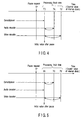
- FIG. 4 is a view illustrating time points indicated by (the counter values of) the three internal clocks appearing in FIG. 1, and useful in explaining the process of returning the time points indicated by the internal clocks of an audio decoder and a video decoder to a time point indicated by the internal clock of the demultiplexer; and
- FIG. 5 is a view illustrating time points indicated by (the counter values of) the three internal clocks appearing in FIG. 1, and useful in explaining the process of returning the other two time points to the earliest time point.
-
- An embodiment of the present invention will be described with reference to the accompanying drawings. FIG. 1 is a schematic block illustrating an apparatus for synchronously reproducing audio and video data according to the embodiment.
- This apparatus comprises a demultiplexer 1 for receiving a multiplexed bitstream as an input signal, and separating the multiplexed bitstream into video data and audio data; an
audio decoder 2 for receiving and decoding audio data separated by the demultiplexer 1; and avideo decoder 3 for receiving and decoding video data separated by the demultiplexer 1. - The demultiplexer 1,
audio decoder 2 andvideo decoder 3 are provided withinternal clocks audio decoder 2 is temporarily stored in abuffer 22 and then input to a voice output device 5 such as a loudspeaker. The output of thevideo decoder 3 is temporarily stored in abuffer 32 and then input to a video output device 6 such as an LCD. - The demultiplexer 1 includes a
clock setting section 11. Theclock setting section 11 is configured to receive a pause request signal generated from, for example, a CPU, and to set the time indicated by each internal clock (12, 21 and 31). - FIG. 2 shows an example of a multiplexed bitstream. The multiplexed bitstream comprises a media identification ID, a presentation time stamp, a payload length and a payload. In the bitstream example of FIG. 2, a video payload follows an audio payload.
- The media identification ID is used to identify whether the successive payload is an audio payload or a video payload. For example, the identification ID of 1 indicates an "audio" payload, and the identification ID of 2 indicates a "video" payload. The presentation time stamp indicates the presentation timing of each payload, using a numerical value in the unit of, for example, "ms". The payload length indicates the length of a payload arranged next to the payload length field, in the unit of "bytes". However, this embodiment is not limited to this format.
- On the basis of such field information, the demultiplexer 1 subjects a multiplexed bitstream to separation processing. The demultiplexer 1 imparts respective time stamps and payloads to the
audio decoder 2 and thevideo decoder 3. - Upon receiving an external reproduction start command, the
internal clocks audio decoder 2 andvideo decoder 3 are operating, theinternal clocks - The
audio decoder 2 decodes audio data coded by a coding method such as AAC, G.729, AMR or MPEG2, etc., thereby comparing a presentation time stamp (PTS) attached to the audio data with an internal time (TA) indicated by theinternal clock 21. If PTS ≧ TA, theaudio decoder 2 outputs a audio signal to the voice output device 5 via thebuffer 22. - Similarly, the
video decoder 3 decodes video data coded by a coding method such as MPEG1, MPEG2, MPEG4, H.261 or H.263, etc., thereby comparing a presentation time stamp (PTS) attached to the video data with an internal time (TV) indicated by theinternal clock 32. If PTS ≧ TV, thevideo decoder 3 outputs a video signal to the video output device 6 via thebuffer 32. - Suppose, here, a case where a pause process is executed while the demultiplexer 1,
audio decoder 2 andvideo decoder 3 are operating. Upon receiving an external pause request, the demultiplexer 1,audio decoder 2 andvideo decoder 3 continue current processing on a data frame until they finish the processing. When they stop processing, they stop the operation of their internal clocks. - Specifically, when the demultiplexer 1 has stopped its separation processing, the demultiplexer 1 finishes separation of a payload. Further, when the
decoders decoders - In general, unit-processing time differs between devices. For example, the unit-processing time of the demultiplexer 1 is 10 ms, the unit-processing time of the
audio decoder 2 is 20 ms, and the unit-processing time of thevideo decoder 3 is 33 ms. - Since the internal clocks start their counting after they are reset, the counter values of the internal clocks are identical before the internal clocks receive a pause request. However, when the devices have finished their processing after receipt of a pause request, their internal clocks indicate different internal times.
- Suppose a case where a pause process is executed when the devices have started their unit processing. In this case, the internal time (TD) of the demultiplexer 1 is the sum of the processing time (10 ms) required for the unit processing and the time point (TP) at which the pause request has been issued. Similarly, the internal time (TA) of the
audio decoder 2 is the sum of 20 ms and TP, and the internal time (TV) of thevideo decoder 3 is the sum of 33 ms and TP. - If the devices having their respective internal times resume reproduction in response to a request to release the pause, voice output and video output are executed at different timings since the internal clocks of the devices indicate different times.
- Furthermore, if there is a device having its internal time advanced from the pause request time (TP), and the initial frame after the resumption of reproduction has a time stamp earlier than the internal time, the initial frame will not be reproduced.
- To avoid the above problems, in the embodiment, the internal times indicated by the internal clocks are set to the same value before the resumption of reproduction. The initial value setting executed when resuming reproduction prevents voice and video signals from being output at different timings after the resumption of reproduction.
- FIGS. 3 - 5 show examples, in which the internal times are set to an initial value in different manners.
- In the case of FIG. 3, the internal times (TD, TA and TV) are adjusted to the pause request time (TP). In the case of FIG. 4, the internal times (TA and TV) are adjusted to the internal time (TD) of the demultiplexer 1 after the pause.
- Further, it is not always necessary to set the internal times to a fixed time such as TD or TP. The internal times may be adjusted to the earliest time after the pause (i.e. to the internal time of a device that stops earliest). FIG. 5 shows an example of this case. In the case of FIG. 5, since the
audio decoder 2 has finished the processing earliest, the internal times of the other devices are adjusted to the internal time (TA) indicated by the internal clock of theaudio decoder 2. - The output of the demultiplexer 1 is supplied to each decoder via a buffer (not shown). Accordingly, if the internal time (TD) of the demultiplexer 1 is used as the initial value for the internal clocks after the resumption of reproduction, the frames before the time TD have been already sent to the buffer.
- Moreover, the
buffers audio decoder 2 andvideo decoder 3, respectively, temporarily store decoded data. Accordingly, even if there is a pause request during a decoding process in eachdecoder buffers - Consequently, data output from the audio and
video decoder - The apparatus and method for synchronously reproducing audio and video data, according to the embodiment of the present invention, can be used when there is reproduction data which is reproduced. For example, the apparatus and method can be used in a video viewer in a mobile phone, a PDA (Personal Digital Assistant), an HDD (Hard Disk Drive) decoder and a DVD (Digital Video Disk). In addition, they can be also used in a digital camera for reproducing recorded data.
- The setting of the counter value of the internal clock (21 or 32) of each decoder (2 or 3) to a single value before a pause in reproduction enables the output time point of audio and video data to be adjusted to a reference time point when reproduction of data is resumed after the pause is released. Further, the adjustment of the internal time of each decoder (2 or 3) as above can prevent a defect from resulting from different data-output timings during data reproduction.
- The internal clocks (12, 21 and 32) can be adjusted to indicate any appropriate time. Since the demultiplexer 1, the
audio decoder 2 and thevideo decoder 3 have their respective internal clocks, it is preferable to set a reference time to the counter value of the internal clock of one of the devices. - For example, the internal clock (21 or 32) of each decoder (2 or 3) may be set to indicate a time identical to the stop time of the
internal clock 12 of the demultiplexer 1. The stop time is assumed as the time when the demultiplexer 1 has finished its separation processing. Furthermore, the internal clock (21 or 32) of each decoder (2 or 3) may be set to indicate the time identical to the stop time of one of the internal clocks (12, 21 and 32) which has stopped earliest when the devices have finished their respective processes. - The counter values of the internal clocks (12, 21 and 32) may be adjusted at any desired time point. For example, the time when a pause request has been issued may be used as the initial value for the internal clocks (12, 21 and 32). Alternatively, the time indicated by the internal clock (21 or 32) of one of the
audio decoder 2 and thevideo decoder 3 which has finished its processing latest may be used as the internal time of theinternal clock 12 of the demultiplexer 1.
Claims (10)
- An audio and video data synchronous reproduction method for decoding, using an audio decoder, audio data separated by a demultiplexer from the multiplexed stream in which audio data, video data and a time stamp are multiplexed, and decoding, using a video decoder, video data separated by the demultiplexer from the multiplexed stream, the method being characterized by comprising:pausing (1) reproduction processing on audio and video data in response to a request to pause the reproduction of the audio and video data;resuming (1) the reproduction processing on the audio and video data in response to a request to release the pause in the reproduction of the audio and video data; andsetting (11), before the resuming, internal clocks (12, 21, 31) to indicate a single time, the clocks which are respectively included in the demultiplexer (1), the audio decoder (2) and the video decoder (3).
- The method according to claim 1, characterized by further comprising determining the timing of the reproduction processing by comparing the times indicated by the internal clocks (12, 21, 31) with the time stamp.
- The method according to claim 1, characterized in that the setting comprises setting (11), before the resuming, the times indicated by the internal clocks (21, 31) of the audio decoder (2) and the video decoder (3) to the time indicated by the internal clock (12) of the demultiplexer (1).
- The method according to claim 1, characterized in that the setting comprises setting (11), before the resuming, the times indicated by the respective internal clocks (12, 21, 31) of the demultiplexer (1), the audio decoder (2) and the video decoder (3) to the smallest value in the times indicated by the internal clocks (12, 21, 31).
- The method according to claim 1, characterized in that the setting comprises setting (11), before the resuming, the times indicated by the respective internal clocks (12, 21, 31) of the demultiplexer (1), the audio decoder (2) and the video decoder (3) to the time when the request to release the pause has been issued.
- An audio and video data synchronous reproduction apparatus for decoding, using an audio decoder, audio data separated by a demultiplexer from the multiplexed stream in which audio data, video data and a time stamp are multiplexed, and decoding, using a video decoder, video data separated by the demultiplexer from the multiplexed stream, the apparatus being characterized by comprising:a pause section (1) configured to pause reproduction processing on audio and video data in response to a request to pause the reproduction of the audio and video data;a resuming section (1) configured to resume the reproduction processing on the audio and video data in response to a request to release the pause in the reproduction of the audio and video data; anda setting section (11) configured to set, before the resumption of the reproduction processing, internal clocks (12, 21, 31) to indicate a single time, the clocks which are respectively included in the demultiplexer (1), the audio decoder (2) and the video decoder (3).
- The apparatus according to claim 6, characterized by further comprising a determination section (1) configured to determine the timing of the reproduction processing by comparing the times indicated by the internal clocks (12, 21, 31) with the time stamp.
- The apparatus according to claim 6,
characterized in that the setting section (11) sets, before the resumption of the reproduction processing, the times indicated by the internal clocks (21, 31) of the audio decoder (2) and the video decoder (3) to the time indicated by the internal clock (12) of the demultiplexer (1). - The apparatus according to claim 6, characterized in that the setting section (11) sets, before the resumption of the reproduction processing, the times indicated by the respective internal clocks (12, 21, 31) of the demultiplexer (1), the audio decoder (2) and the video decoder (3) to the smallest value in the times indicated by the internal clocks.
- The apparatus according to claim 6, characterized in that the setting section (11) sets, before the resumption of the reproduction processing, the times indicated by the respective internal clocks (12, 21, 31) of the demultiplexer (1), the audio decoder (2) and the video decoder (3) to the time when the request to release the pause has been issued.
Applications Claiming Priority (2)
| Application Number | Priority Date | Filing Date | Title |
|---|---|---|---|
| JP2000392287A JP2002197794A (en) | 2000-12-25 | 2000-12-25 | Audio / video data synchronous playback method |
| JP2000392287 | 2000-12-25 |
Publications (1)
| Publication Number | Publication Date |
|---|---|
| EP1231791A2 true EP1231791A2 (en) | 2002-08-14 |
Family
ID=18858294
Family Applications (1)
| Application Number | Title | Priority Date | Filing Date |
|---|---|---|---|
| EP20010130506 Withdrawn EP1231791A2 (en) | 2000-12-25 | 2001-12-21 | Method and apparatus for synchronously reproducing audio and video data |
Country Status (3)
| Country | Link |
|---|---|
| US (1) | US7218841B2 (en) |
| EP (1) | EP1231791A2 (en) |
| JP (1) | JP2002197794A (en) |
Families Citing this family (12)
| Publication number | Priority date | Publication date | Assignee | Title |
|---|---|---|---|---|
| US7953194B2 (en) * | 2002-09-27 | 2011-05-31 | Broadcom Corporation | Handling video transition errors in video on demand streams |
| US7366462B2 (en) * | 2003-10-24 | 2008-04-29 | Qualcomm Incorporated | Method and apparatus for seamlessly switching reception between multimedia streams in a wireless communication system |
| US20050216752A1 (en) * | 2004-03-26 | 2005-09-29 | Microsoft Corporation | Common scrambling |
| US20060036551A1 (en) * | 2004-03-26 | 2006-02-16 | Microsoft Corporation | Protecting elementary stream content |
| US20060184790A1 (en) * | 2004-03-26 | 2006-08-17 | Microsoft Corporation | Protecting elementary stream content |
| JP2005327000A (en) * | 2004-05-13 | 2005-11-24 | Sony Corp | User interface control device, user interface control method, and computer program |
| KR100532613B1 (en) * | 2004-06-18 | 2005-12-01 | 삼성전자주식회사 | Optical recording apparatus and control method thereof |
| JP4207869B2 (en) | 2004-08-30 | 2009-01-14 | ソニー株式会社 | Reproduction control method and reproduction apparatus |
| US7684566B2 (en) | 2005-05-27 | 2010-03-23 | Microsoft Corporation | Encryption scheme for streamed multimedia content protected by rights management system |
| US8321690B2 (en) | 2005-08-11 | 2012-11-27 | Microsoft Corporation | Protecting digital media of various content types |
| JP5115549B2 (en) * | 2007-03-20 | 2013-01-09 | 富士通株式会社 | Decoding method, decoder and decoding apparatus |
| US10142585B2 (en) * | 2015-04-28 | 2018-11-27 | Rovi Guides, Inc. | Methods and systems for synching supplemental audio content to video content |
Family Cites Families (4)
| Publication number | Priority date | Publication date | Assignee | Title |
|---|---|---|---|---|
| JP3100308B2 (en) | 1995-03-14 | 2000-10-16 | 日本ビクター株式会社 | Image and audio information playback system |
| TW436777B (en) * | 1995-09-29 | 2001-05-28 | Matsushita Electric Industrial Co Ltd | A method and an apparatus for reproducing bitstream having non-sequential system clock data seamlessly therebetween |
| JPH10262208A (en) | 1997-03-19 | 1998-09-29 | Sony Corp | Synchronization control apparatus and method |
| US6801707B1 (en) * | 1999-09-20 | 2004-10-05 | Matsushita Electric Industrial Co., Ltd. | Encoding/recording device that suspends encoding for video data and sampling for an audio signal in response to a recording pause instruction so as to allow data recorded before and after recording pause to be continuously reproduced |
-
2000
- 2000-12-25 JP JP2000392287A patent/JP2002197794A/en active Pending
-
2001
- 2001-12-20 US US10/022,252 patent/US7218841B2/en not_active Expired - Fee Related
- 2001-12-21 EP EP20010130506 patent/EP1231791A2/en not_active Withdrawn
Also Published As
| Publication number | Publication date |
|---|---|
| US7218841B2 (en) | 2007-05-15 |
| JP2002197794A (en) | 2002-07-12 |
| US20020082845A1 (en) | 2002-06-27 |
Similar Documents
| Publication | Publication Date | Title |
|---|---|---|
| US6163647A (en) | Apparatus for synchronized playback of audio-video signals | |
| CN100382566C (en) | Video data processing device | |
| US7218841B2 (en) | Method and apparatus for synchronously reproducing audio and video data | |
| US20040264577A1 (en) | Apparatus and method for controlling the synchronization of a video transport stream | |
| JPH10208453A (en) | Synchronization of audio-visual stream synchronized to clock with video display synchronized to different clock | |
| CN2927556Y (en) | Video and audio re-player, outputting-time converter | |
| US7551839B2 (en) | Method of generating video reproduction synchronizing signal, program for generating video reproduction synchronizing signal, timing control apparatus, method of synchronously reproducing video and audio, program for synchronously reproducing video and audio, and apparatus for synchronously reproducing video and audio | |
| US6233695B1 (en) | Data transmission control system in set top box | |
| JP3100308B2 (en) | Image and audio information playback system | |
| KR100619041B1 (en) | Video Synchronizer and Video Synchronization Method | |
| KR101086920B1 (en) | Use Discrete Indicators for Trick Mode Operation | |
| JP2001231035A (en) | Decoding synchronization control device, decoding device, and decoding synchronization control method | |
| JP2001346166A (en) | Method and apparatus for reproducing compressed encoded data | |
| JP3184175B2 (en) | Decryption device | |
| JP2004228627A (en) | Data processing apparatus, data reproducing apparatus, data processing method, and data reproducing method | |
| EP1871108B1 (en) | Recording device, reproducing device, recording medium, recording method, and lsi | |
| JP2003339023A (en) | Video playback device | |
| KR100499519B1 (en) | Method for Controlling Audio Lip-Synchronization | |
| JP4850041B2 (en) | Video playback system, video playback synchronization method, and video playback terminal | |
| JP4373654B2 (en) | Multimedia decoding / playback apparatus and synchronization control method thereof | |
| JP4579877B2 (en) | Playback apparatus and playback method | |
| US7382972B2 (en) | Recording apparatus and method | |
| JP2001320704A (en) | Image decoding device and image decoding method | |
| JP2007081534A (en) | Decoding and playback device | |
| KR100499518B1 (en) | Method for Controlling Audio Lip-Synchronization |
Legal Events
| Date | Code | Title | Description |
|---|---|---|---|
| PUAI | Public reference made under article 153(3) epc to a published international application that has entered the european phase |
Free format text: ORIGINAL CODE: 0009012 |
|
| 17P | Request for examination filed |
Effective date: 20011221 |
|
| AK | Designated contracting states |
Kind code of ref document: A2 Designated state(s): AT BE CH CY DE DK ES FI FR GB GR IE IT LI LU MC NL PT SE TR |
|
| AX | Request for extension of the european patent |
Free format text: AL;LT;LV;MK;RO;SI |
|
| STAA | Information on the status of an ep patent application or granted ep patent |
Free format text: STATUS: THE APPLICATION HAS BEEN WITHDRAWN |
|
| 18W | Application withdrawn |
Effective date: 20080115 |