EP1231752A2 - Video encoding scheme supporting the transport of audio and auxiliary information - Google Patents
Video encoding scheme supporting the transport of audio and auxiliary information Download PDFInfo
- Publication number
- EP1231752A2 EP1231752A2 EP02250463A EP02250463A EP1231752A2 EP 1231752 A2 EP1231752 A2 EP 1231752A2 EP 02250463 A EP02250463 A EP 02250463A EP 02250463 A EP02250463 A EP 02250463A EP 1231752 A2 EP1231752 A2 EP 1231752A2
- Authority
- EP
- European Patent Office
- Prior art keywords
- data
- bit
- enhanced
- encoding
- state
- Prior art date
- Legal status (The legal status is an assumption and is not a legal conclusion. Google has not performed a legal analysis and makes no representation as to the accuracy of the status listed.)
- Withdrawn
Links
Images


Classifications
-
- H—ELECTRICITY
- H04—ELECTRIC COMMUNICATION TECHNIQUE
- H04L—TRANSMISSION OF DIGITAL INFORMATION, e.g. TELEGRAPHIC COMMUNICATION
- H04L25/00—Baseband systems
- H04L25/38—Synchronous or start-stop systems, e.g. for Baudot code
- H04L25/40—Transmitting circuits; Receiving circuits
- H04L25/49—Transmitting circuits; Receiving circuits using code conversion at the transmitter; using predistortion; using insertion of idle bits for obtaining a desired frequency spectrum; using three or more amplitude levels ; Baseband coding techniques specific to data transmission systems
- H04L25/4906—Transmitting circuits; Receiving circuits using code conversion at the transmitter; using predistortion; using insertion of idle bits for obtaining a desired frequency spectrum; using three or more amplitude levels ; Baseband coding techniques specific to data transmission systems using binary codes
Definitions
- DVI standard Digital Visual Interfaces
- DVI 1.0 specification the video encoder encodes video data into 10 bit words. For each word, bits 7:0 are selectively complimented, and bit 8 defines the complimenting method.
- the encoder considers the DC biasing of bits 8:0, and depending on a computation, bits 7:0 are inverted if inversion improves the long term DC biasing.
- the encoder then uses bit 9 to indicate the state of inversion, i.e., whether bits 7:0 have been inverted.
- the 10 bit words are communicated, and eventually received by a decoder.
- the decoder For each 10 bit word, the decoder considers bit 9 to determine whether the encoder has inverted bits 7:0. If bit 9 indicates that the bits 7:0 have been inverted, then the encoder performs its own inversion of bits 7:0 to recapture the original data. The overall result is a video data stream that is generally more DC balanced.
- the method comprises receiving first data (e.g., video) and second data (e.g., audio).
- the first data is encoded based on the state of at least one bit of the second data.
- the first data and second data are then packaged into a single word, which is then communicated to a remote decoder, for example.
- DC balancing may be performed on the first data before it is communicated as part of the single word.
- a logic operation is selected that will result in a state which is closest to the desired state, and the logic operation is performed on at least a portion of the data.
- the present invention relates a system for transmitting auxiliary data in video encoding.
- the system includes un-enhanced and enhanced encoders and un-enhanced and enhanced decoders.
- the un-enhanced decoder is adapted to communicate with the un-enhanced and enhanced decoders, while the enhanced decoder is adapted to communicate with both the un-enhanced and enhanced decoders.
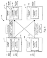
- Fig. 1 illustrates a block diagram of an overall video encoding/decoding system 100 in accordance with one embodiment of the present invention.
- the system 100 comprises an un-enhanced encoder 101, and enhanced encoder 111, and un-enhanced decoder 107 and an enhanced decoder 105.
- the un-enhanced encoder 101 receives a first data input in an un-encoded form.
- the un-enhanced encoder 101 applies an un-enhanced encoding functionality 103 to the first data input to generates one or more encoded first data bit(s) identified as "N" bits.
- the un-enhanced encoder 101 also generates one or more decoder instruction bit(s) based on the modification applied in the encoding process of the first data input and identified as "M" bits.
- the "N" data bits and "M” decoder instruction bits are packaged into a word (N + M) for delivery.
- word is transmitted or delivered across a communication link such as a DVI interface to an enhanced decoder 105 or an un-enhanced decoder 107.
- the un-enhanced decoder 107 Upon receiving the N + M word, the un-enhanced decoder 107 uses un-enhanced decoding functionality 109 to recreate the original first data, which is then output as first data output by the un-enhanced decoder 107.
- the decoding process involved is directed by the "M" decoder instruction bits received from the un-enhanced encoder 101.
- the enhanced decoder 105 Upon receiving the N + M word, the enhanced decoder 105 generates and recreates the first data output using the same functionality. This is accomplished by employing an un-enhanced modifier functionality 108, similar to the un-enhanced decoding functionality 109 previously described in association with the un-enhanced decoder 107. Particularly, the "M" decoder instruction bits are applied by the enhanced decoder 105, and are used by the un-enhanced decoding functionality 108 to recreate the original first data, which is then output as the first data output by the enhanced decoder 105.
- system 100 includes the enhanced encoder 111 which receives a first and second data input in an un-encoded form.
- the enhanced encoder 111 applies enchanced encoding functionality 113 to the first data input to generate one or more encoded first data bit(s), identified as "N" bits and to the second data input to generate one or more encoded second data bit(s), identified as "J" bits.
- encoding the second input data may simply comprise passing the received second data.
- the enhanced encoder 111 also generates one or more decoder instruction bit(s), identified as "K" bits based on the modification applied in encoding the first and second data inputs.
- the "N" first data bits (with or without decoder compensation), "J" second data bits and "K” decoder instruction bits are packaged into a word (N + J + K) for delivery.
- the word is delivered or transmitted across a communication link such as a DVI interface for example to the enhanced decoder 105 or the un-enhanced decoder 107.
- the enhanced decoder 105 Upon receiving the N + J + K word, the enhanced decoder 105 uses enhanced decoding functionality 106 to decode the word based on the k decoder instruction bits. The enhanced decoder 105 decodes the word into the original first and second data, which is then output as the first and second data outputs by the enhanced decoder 105.
- the enhanced encoder 111 simply communicates the encoded word N + J + K to the un-enhanced decoder 107 without any decoder compensation.
- the un-enhanced decoder 107 simply interprets the "J" second data bit(s) as decoder instruction bit(s), and decodes the first data according to the "J" second data bit(s) and the "K" decoder instruction bit(s). If the "J" second data bit(s) match what the un-enhanced decoder 107 expects as instruction bit(s), then decoding occurs without any degradation of the first data. If the "J" second data bits do not match what the un-enhanced decoder 107 expects, some degradation of the first data may occur.
- An encoding scheme may be selected such that, in a majority of circumstances, end users cannot readily detect the degradation.
- the enhanced encoder 111 may perform decoder compensation on the first data. Specifically, for example, the enhanced encoder 111 analyzes the encoded second data bit(s) and determines whether, based on the encoding of the first data bits, the second data bit(s) match what the un-enhanced decoder 107 expects as decoder instruction bit(s). If the second data bit(s) match the expected decoder instruction bit(s), the enhanced encoder 111 simply communicates the first data bits as is to the un-enhanced decoder 107.
- the enhanced encoder 111 anticipates, based on the "J" second data bits and the "K” decoder instruction bits, the result of the decoding process to be applied by the un-enhanced decoder 107 on the "N" first data bits, and modifies at least one of the "N" first data bits to counteract the result.
- some type of decoder compensation may be employed on the first data bit(s), whether or not the second data bit(s) match what the un-enhanced decoder 107 expects as decoder instruction bits. In other words, if the second data bit(s) and the expected decoder instruction bit(s) match, a first type of compensation may be employed, and if they don't match, a second type of compensation may be employed.
- Fig. 2 illustrates a flow diagram of a decoding compensation scheme in accordance with one embodiment of the present invention.
- the first and second data are encoded as illustrated by block 201.
- the state of inversion of the first data bits resulting from the encoding process is determined as illustrated by block 203.
- the bits representing the first data are either left alone or inverted, partially to assist in DC balancing.
- the state of inversion (e.g., inversion expected by a remote decoder) is compared to at least one bit of second data as illustrated by diamond 205. If the state of inversion matches the second data bit, the first data and the second data bit(s) are communicated to the remote decoder as illustrated by block 207. If the state of inversion does not match the second data bit, at least one of the first data bits is/are inverted, as illustrated by block 209, before the first data bits and second data bits are communicated to the remote decoder as illustrated by block 207.
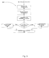
- Fig. 3 illustrates a high level flow diagram of an encoding scheme, generally designated 300, with decoding compensation in accordance with one embodiment of the present information.
- An audio stream transmission may include for example audio data, synchronization data and packet header information.
- the transmission is received as illustrated by block 310.
- the transmission is DC balanced as illustrated by block 312.
- An intermediate value K i.e., a intermediate value for the K decoder instruction bit(s) is determined as illustrated by block 314.
- the scheme determines if the intermediate value K is equal to the audio bits "a" as illustrated by diamond 316. If the intermediate value k is equal to the audio bits, "a" then the actual data bits are encoded as illustrated by block 318. The encoded data is then output as illustrated by block 322. If the intermediate value K is not equal to the audio bits A, then the actual data bits are inverted and encoded as illustrated by block 320. The encoded data is output as illustrated by block 322.
- Fig. 4 illustrates one embodiment of an enhanced encoding scheme, generally designated 400, including decoding compensation in the case where a DVI encoder is used.
- the input (i.e., second) data may be audio and/or auxiliary data.
- the audio stream(s) and auxiliary stream(s) are converted into a single serial stream.
- the serial stream is then broken into 3 serial streams using a 1-3 demux circuit for example. It is contemplated that, in one embodiment of the present invention, the serial streams are transmitted over a communication link having 3 channels for example, where each of the 3 serial streams is transmitted over one of the 3 channels
- an audio stream may be constructed with audio data, synchronization data and packet header information.
- DVI digital versatile interface
- one of the instruction bits, bit 9 for example is replaced with a second data bit, such as an audio bit, for example, on each of the 3 DVI channels.
- one of the instruction bits is replaced with such a second data bit only when active video is being transmitted (i.e., when the data enable or "DE" is high or equal to 1) as illustrated by diamond 410. If DE is not equal to 1, then the sync data is being transmitted, and not active video, as illustrated by block 412.
- the transmission is decoded as illustrated by block 414; diamond 416 and blocks 418, 420, and 421; and diamond 422 and block 424.
- the decoded transmission is DC balanced as illustrated by diamond 426 and blocks 428 and 430.
- Such DC balancing may include determining the historical weight for the decoded transmission and adjusting such DC balancing over time if necessary.
- the intermediate value K is compared with the audio bits as illustrated by diamond 442 and as provided previously. If the value K is equal to value A, the actual data bits are encoded as illustrated by block 438. The encoded data is then output as illustrated by block 436. If the intermediate value K is not equal to value A, then the actual data bits are inverted and encoded as illustrated by block 434. The encoded data is then output as illustrated by block 436.
- Fig. 4 illustrates that, if desired, synchronization words are transmitted on these bits during the first 10 video pixels, for example, following the blanking period.
- audio header information is next transmitted.
- audio data is next transmitted.
- a sync pulse may also be "notched" to indicate the presence of audio and/or other second data. Such "notch" may include a stutter at the leading edge of sync for example although other embodiments are contemplated.
- bit 9 is transmitted in normal DVI fashion.
- Some benefits of such transmission to enhanced decoders include: (1) little or no degradation; (2) substantial throughput (e.g., 640 x 480 @ 60Hz, more than 55Mbps raw throughput, and more than 49Mbps throughput after the header and sync word are considered); and (3) the data is still somewhat DC balanced.
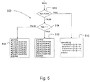
- Fig. 5 illustrates a flow diagram of a decoding operation for use in connection with the encoding scheme of Fig. 4.
- the decoded transmission is not DC balanced as provided previously.
- one of the instruction bits is replaced with a second data bit only during active video. It is determined if sync words are being transmitted as illustrated by diamond 510. If sync words, are being transmitted, and not active video, the data is not decoded as illustrated by block 512.
- the scheme uses logic functions to balance the word towards a stronger 0 or 1 presence. It is determined if received bit 8 is equal to 1 as illustrated by diamond 514. If the received 8 bit is not equal to 1, the received data may be logically combined using an exclusive nor function (alternatively referred to as "XNOR) as illustrated by block 516. If however, the received 8th bit is equal to 1, the received data may be logically combined using an exclusive or function (alternatively referred to as "XOR) as illustrated by block 518.
- XNOR exclusive nor function
- XOR exclusive or function
- DC balancing is not used.
- a second data bit e.g., audio
- the encoder inverts or does not invert one or more of the first data bits (e.g., video).
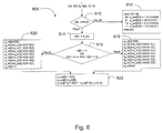
- Fig. 6 illustrates one example of this alternative embodiment. More particularly Fig. 6 illustrates a flow diagram of an encoding scheme, generally designated 600, that produce a DVI 1.0 compatible code word containing video and other (e.g., audio) data.
- DE active video
- DC balancing is still used.
- NRZIO or NRZI1 encoding is used, for example, and bit 8 is set to be compatible with DVI.
- bit 8 is set to all 0 or all 1 in each word.
- Bit 9 is then used for DC balancing.
- Second data e.g., audio
- the second data can be transmitted during the blanking periods also as described in other blanking period mechanisms
- bit 9 (along with bit 8) is simply set to be compatible with DVI.
- each of bit 9 and bit 8 are set to be all 0 or all 1 in each word. Second data is then again transmitted during the blanking period, as mentioned above.
- encoding is performed based on the second data (e.g., audio for example, although other data is contemplated).
- second data is sent in bit 8 and NRZI0 or NRZI1 encoding, for example, is performed based on that bit, not on the numbers of 0's or 1's.
- DC balancing can then be performed using bit 9. This provides backward compatibility with most manufacturer's DVI 1.0 receivers, DC balancing, and the ability to transmit second data in the 10-bit word.
- DC balancing is not used. Specifically, both bit 9 and bit 8 are used to transmit second data, and encoding is performed based on the state of one of the second data bits (bit 8).
- bit 9 is either fixed to 0 or 1, used to transmit second data (e.g., audio), or set for traditional balancing.
- Bit 8 is then used to perform pre-balancing or intra-word DC balancing. Specifically, for example, if a weighting factor exists in the cumulative history towards 0, then it may be desirable to make a particular word a stronger 1 presence. This may be achieved by either using exclusive OR or exclusive NOR. Specifically, a determination is made as to which operation (exclusive OR or exclusive NOR) provides the most number of 1's.
Landscapes
- Physics & Mathematics (AREA)
- Spectroscopy & Molecular Physics (AREA)
- Engineering & Computer Science (AREA)
- Computer Networks & Wireless Communication (AREA)
- Signal Processing (AREA)
- Compression, Expansion, Code Conversion, And Decoders (AREA)
- Compression Or Coding Systems Of Tv Signals (AREA)
Abstract
Description
Claims (21)
- A method of transmitting auxiliary data in video encoding comprising:receiving first and second data;encoding said first data based on a state of at least one bit of said second data; andpackaging said encoded first data and said second data into a single word; andcommunicating said single word.
- The method of claim 1, further comprising DC balancing said first data.
- The method of Claim 1, wherein encoding said first data further comprises determining whether said first data should be inverted.
- The method of Claim 3, wherein encoding said first data further comprises comparing a state of inversion of said first data to said state of said at least one bit of said second data.
- The method of Claim 4, wherein encoding said first data further comprises inverting said first data if said state of inversion of said first data does not match said state of said at least one bit of said second data.
- The method of Claim 4, wherein encoding said first data bit further comprises not inverting said first data if said state of inversion of said first data matches said state of said at least one bit of said second data.
- The method of Claim 1, wherein encoding said first data comprises determining an intermediate value for said first data.
- The method of Claim 7, wherein encoding said first data further comprises comparing said intermediate value to at least one bit of audio data.
- The method of Claim 8, wherein encoding said first data further comprises encoding said first data and said audio data if said state of inversion of said first data bit is equal to said at least one bit of audio data.
- The method of Claim 7, wherein encoding said first data further comprises inverting said first data if said state of inversion of said first data does not match said state of said at least one bit of audio data.
- The method of Claim 10, wherein encoding said first data further comprises encoding said inverted first data and said at least one bit of audio data.
- A method of balancing a code word in a video encoder comprising:receiving data;determining a desired state of said data; andencoding said data based on the desired state of the data.
- A method of balancing a code word in video encoder comprising:receiving data;determining a desired state of said data;selecting a logic operation that will result in a state closest to said desired state; andperforming said selected logic operation on at least a portion of said data.
- The system of Claim 13, wherein performing said logic operation comprises performing an exclusive nor operation.
- The system of Claim 13, wherein said desired state includes data having a strong 1 presence.
- The system of Claim 13, wherein performing said logic operation comprises performing an exclusive or operation.
- The system of Claim 13, wherein said desired state includes data having a strong 0 presence.
- A system for transmitting auxiliary data in video encoding comprising:a receiver adapted to receive first and second data;an encoder adapted to encode said first data based on at least one bit of said second data;a packaging device adapted to package said encoded first and second data into a single word; anda communication device adapted to communicate said single word.
- A system for transmitting auxiliary data in video encoding comprising:an un-enhanced encoder;an enhanced encoder;an un-enhanced decoder adapted to communicate with said un-enhanced and enhanced encoders; andan enhanced decoder adapted to communicate with said un-enhanced and enhanced encoders.
- The system of Claim 19, wherein said enhanced decoder is adapted to communicate enhanced data word.
- The system of Claim 19, wherein said un-enhanced encoder is adapted to communicate un-enhanced data word.
Applications Claiming Priority (20)
| Application Number | Priority Date | Filing Date | Title |
|---|---|---|---|
| US26379201P | 2001-01-24 | 2001-01-24 | |
| US263792 | 2001-01-24 | ||
| US26884001P | 2001-02-14 | 2001-02-14 | |
| US268840P | 2001-02-14 | ||
| US31315701P | 2001-08-16 | 2001-08-16 | |
| US313157P | 2001-08-16 | ||
| US31344101P | 2001-08-17 | 2001-08-17 | |
| US313441P | 2001-08-17 | ||
| US31361001P | 2001-08-20 | 2001-08-20 | |
| US313610P | 2001-08-20 | ||
| US31413701P | 2001-08-21 | 2001-08-21 | |
| US314137P | 2001-08-21 | ||
| US09/951,671 US7356051B2 (en) | 2001-01-24 | 2001-09-12 | Digital visual interface with audio and auxiliary data cross reference to related applications |
| US951289 | 2001-09-12 | ||
| US951671 | 2001-09-12 | ||
| US09/951,289 US20020097869A1 (en) | 2001-01-24 | 2001-09-12 | System and method for increased data capacity of a digital video link |
| US34414 | 2001-12-27 | ||
| US10/034,414 US8798166B2 (en) | 2001-08-17 | 2001-12-27 | Video encoding scheme supporting the transport of audio and auxiliary information |
| US34383 | 2001-12-27 | ||
| US10/034,383 US20030070132A1 (en) | 2001-08-16 | 2001-12-27 | Flexible video encoding scheme supporting audio and auxiliary information |
Publications (2)
| Publication Number | Publication Date |
|---|---|
| EP1231752A2 true EP1231752A2 (en) | 2002-08-14 |
| EP1231752A3 EP1231752A3 (en) | 2006-11-15 |
Family
ID=27580760
Family Applications (2)
| Application Number | Title | Priority Date | Filing Date |
|---|---|---|---|
| EP02250463A Withdrawn EP1231752A3 (en) | 2001-01-24 | 2002-01-23 | Video encoding scheme supporting the transport of audio and auxiliary information |
| EP02250462A Withdrawn EP1231751A3 (en) | 2001-01-24 | 2002-01-23 | Flexible video encoding scheme supporting audio and auxiliary information |
Family Applications After (1)
| Application Number | Title | Priority Date | Filing Date |
|---|---|---|---|
| EP02250462A Withdrawn EP1231751A3 (en) | 2001-01-24 | 2002-01-23 | Flexible video encoding scheme supporting audio and auxiliary information |
Country Status (1)
| Country | Link |
|---|---|
| EP (2) | EP1231752A3 (en) |
Family Cites Families (2)
| Publication number | Priority date | Publication date | Assignee | Title |
|---|---|---|---|---|
| US5835498A (en) * | 1995-10-05 | 1998-11-10 | Silicon Image, Inc. | System and method for sending multiple data signals over a serial link |
| US5974464A (en) * | 1995-10-06 | 1999-10-26 | Silicon Image, Inc. | System for high speed serial video signal transmission using DC-balanced coding |
-
2002
- 2002-01-23 EP EP02250463A patent/EP1231752A3/en not_active Withdrawn
- 2002-01-23 EP EP02250462A patent/EP1231751A3/en not_active Withdrawn
Also Published As
| Publication number | Publication date |
|---|---|
| EP1231751A3 (en) | 2006-08-02 |
| EP1231751A2 (en) | 2002-08-14 |
| EP1231752A3 (en) | 2006-11-15 |
Similar Documents
| Publication | Publication Date | Title |
|---|---|---|
| US8107742B2 (en) | Encoder and decoder for encoding and decoding pixel data with low amount of transmitting data, encoding method, and decoding method thereof | |
| CN1164082C (en) | Wireless Communication System for Video Packet Transmission | |
| US7146051B2 (en) | Apparatus for and method of transmitting optical signal of graphic signal | |
| US8378860B2 (en) | Method and system for generating high definition multimedia interface (HDMI) codewords using a TMDS encoder/decoder | |
| JPH11506289A (en) | Block coding for digital video transmission | |
| WO1999040727A3 (en) | Method of switching of coded video sequences and corresponding device | |
| US20070011720A1 (en) | HDMI Transmission Systems for Delivering Image Signals and Packetized Audio and Auxiliary Data and Related HDMI Transmission Methods | |
| WO2002073812A1 (en) | Error correction encoding method, error correction decoding method, error correction encoding apparatus, and error correction decoding apparatus | |
| EP1450530B1 (en) | Method to overlay a secondary communication channel onto an encoded primary communication channel | |
| US7102629B2 (en) | System and method for digital video signal transmission | |
| WO2003047274A1 (en) | Image information encoding method and encoder, and image information decoding method and decoder | |
| KR100708078B1 (en) | Digital video data transmission method, reception method, transmission device, and reception device | |
| US8798166B2 (en) | Video encoding scheme supporting the transport of audio and auxiliary information | |
| EP0781054A3 (en) | Method of encoding and decoding for data transmission | |
| US7535836B2 (en) | Method and system to provide word-level flow control using spare link bandwidth | |
| US7460031B2 (en) | Method and apparatus for transmitting/receiving multimedia data | |
| KR20200112084A (en) | Differential signal processing device using for advanced braid clock signaling | |
| US6912008B2 (en) | Method of adding data to a data communication link while retaining backward compatibility | |
| CN119094790A (en) | Image transmission method and system based on inter-frame difference | |
| KR100322594B1 (en) | Method for representing encoding upon coding video information | |
| US20030070132A1 (en) | Flexible video encoding scheme supporting audio and auxiliary information | |
| JP7851023B2 (en) | Transmitter, receiver and transceiver system | |
| EP1231751A2 (en) | Flexible video encoding scheme supporting audio and auxiliary information | |
| JP2024038741A (en) | Transmitting device, receiving device and transmitting/receiving system | |
| KR970011860B1 (en) | Digital terminal for adaptively processing variable coding algorithm |
Legal Events
| Date | Code | Title | Description |
|---|---|---|---|
| PUAI | Public reference made under article 153(3) epc to a published international application that has entered the european phase |
Free format text: ORIGINAL CODE: 0009012 |
|
| AK | Designated contracting states |
Kind code of ref document: A2 Designated state(s): AT BE CH CY DE DK ES FI FR GB GR IE IT LI LU MC NL PT SE TR |
|
| AX | Request for extension of the european patent |
Free format text: AL;LT;LV;MK;RO;SI |
|
| PUAL | Search report despatched |
Free format text: ORIGINAL CODE: 0009013 |
|
| AK | Designated contracting states |
Kind code of ref document: A3 Designated state(s): AT BE CH CY DE DK ES FI FR GB GR IE IT LI LU MC NL PT SE TR |
|
| AX | Request for extension of the european patent |
Extension state: AL LT LV MK RO SI |
|
| RAP1 | Party data changed (applicant data changed or rights of an application transferred) |
Owner name: BROADCOM CORPORATION |
|
| 17P | Request for examination filed |
Effective date: 20070515 |
|
| AKX | Designation fees paid |
Designated state(s): AT BE CH CY DE DK ES FI FR GB GR IE IT LI LU MC NL PT SE TR |
|
| 17Q | First examination report despatched |
Effective date: 20090710 |
|
| STAA | Information on the status of an ep patent application or granted ep patent |
Free format text: STATUS: THE APPLICATION IS DEEMED TO BE WITHDRAWN |
|
| 18D | Application deemed to be withdrawn |
Effective date: 20140801 |