EP1231751A2 - Flexible video encoding scheme supporting audio and auxiliary information - Google Patents
Flexible video encoding scheme supporting audio and auxiliary information Download PDFInfo
- Publication number
- EP1231751A2 EP1231751A2 EP02250462A EP02250462A EP1231751A2 EP 1231751 A2 EP1231751 A2 EP 1231751A2 EP 02250462 A EP02250462 A EP 02250462A EP 02250462 A EP02250462 A EP 02250462A EP 1231751 A2 EP1231751 A2 EP 1231751A2
- Authority
- EP
- European Patent Office
- Prior art keywords
- bit
- data
- concatenating
- onto
- components
- Prior art date
- Legal status (The legal status is an assumption and is not a legal conclusion. Google has not performed a legal analysis and makes no representation as to the accuracy of the status listed.)
- Withdrawn
Links
Images


Classifications
-
- H—ELECTRICITY
- H04—ELECTRIC COMMUNICATION TECHNIQUE
- H04L—TRANSMISSION OF DIGITAL INFORMATION, e.g. TELEGRAPHIC COMMUNICATION
- H04L25/00—Baseband systems
- H04L25/38—Synchronous or start-stop systems, e.g. for Baudot code
- H04L25/40—Transmitting circuits; Receiving circuits
- H04L25/49—Transmitting circuits; Receiving circuits using code conversion at the transmitter; using predistortion; using insertion of idle bits for obtaining a desired frequency spectrum; using three or more amplitude levels ; Baseband coding techniques specific to data transmission systems
- H04L25/4906—Transmitting circuits; Receiving circuits using code conversion at the transmitter; using predistortion; using insertion of idle bits for obtaining a desired frequency spectrum; using three or more amplitude levels ; Baseband coding techniques specific to data transmission systems using binary codes
Definitions
- Prior video encoding schemes have incorporated functionality to minimize bit transition, improving the long term DC biasing.
- a video encoder encodes video data into 10 bit words as part of a high speed digital interface or connection in accordance with commercial applications utilizing Digital Visual Interface (hereinafter referred to as "DVI") frequently make significant use of existing VESA Computer Display standards.
- DVI Digital Visual Interface
- the sequence of timing and video data for particular display resolutions and timing is specified in the VESA Computer Display Monitor Timing standard, Version 1.0, Revision 0.8 dated September 17, 1998, incorporated herein by reference.
- a recent digital television standard set forth in the CEA-EIA 861 specification for high-speed digital interfaces is also incorporated herein by reference.
- the interface provides a connection between a computer and its display device.
- the interface provides a connection between a set top box and a DTV or HDTV.
- DVI interface enables content to remain in a lossless digital domain from creation to consumption; remain display technology independent; support plug and play through hot plug detection, and support EDID protocol; and provide digital and analog support in a single connector.
- bits 7:0 are selectively complimented, and bit 8 defines the complimenting method.
- the encoder considers the DC biasing of bits 8:0 and, depending on a computation, bits 7:0 are inverted if inversion improves the long term DC biasing.
- the encoder then uses bit 9 to indicate the inversion state, i.e., whether bits 7:0 have been inverted.
- the 10 bit words are communicated to, and eventually received by, a decoder.
- the decoder For each 10 bit word, the decoder considers bit 9, determining whether the encoder has inverted bits 7:0. If bit 9 indicates that the bits 7:0 have been inverted, the decoder performs its own inversion of bits 7:0 to recapture the original data. The overall result is a video data stream that is generally more DC balanced.
- the method comprises first receiving input data.
- the received data is then split into one or more components.
- one or more additional data bits are concatenated onto at least one of the components.
- One embodiment of the present invention relates to a method of encoding video.
- the method comprises concatenating at least one data bit onto at least one component of input data and balancing at least one component and at least one data bit.
- at least one CRC bit, audio data, auxiliary data, status information, or some combination thereof may be concatenated onto at least one component.
- Another embodiment of the present invention relates to a method of encoding video comprising registering a received input pixel and splitting the input pixel into a plurality of color components. At least one data bit is concatenated onto the plurality of color components. The color components and the concatenated data bit are then DC balanced and communicated to at least one communication channel.
- video and audio signals are transmitted according to the DVI 1.0 specification similar to that provided previously.
- the encoding scheme previously disclosed is replaced with the following alternative encoding scheme.
- an 8 ⁇ 10 bit ratio similar to that disclosed previously is employed. While an 8 ⁇ 10 bit ratio is discussed other ratios, such as 8 ⁇ 12 or 8 ⁇ 14 for example, are contemplated.
- the code word may be defined as N + M, where N represents the number of bits in a symbol and M represents additional data or code information.
- a code word is comprised of an 8 bit color value (Bits 7:0), a data bit (Bit 8), and an invert indicator bit (Bit 9) used for DC balancing.
- the data bit (Bit 8) represents a cyclical redundancy check bit (alternatively referred to as a "CRC bit"). While a CRC bit is discussed, other embodiments of the present invention may use checksum, auxiliary data, parity and other check or data integrity devices.
- the CRC bit may be computed over all 3 colors of the pixel.
- the resultant CRC word may be, for example, 2 bits in length. In this embodiment, one CRC bit is placed in each of two channels of DVI (for a DVI interface having two channels).
- Digital Video, Audio and Auxiliary (alternatively referred to as "DVAAA”) is representative of the standard for use in the consumer electronics industry for transmitting high quality, multi-channel audio and auxiliary data over a digital video link.
- the final available bit location is reserved for a Data Enable (alternatively referred to as "DE”) indicator bit.
- DE Data Enable
- the resultant CRC word is 3 bits in length.
- one CRC bit is placed in each of three DVAAA channels (for an interface having three channels).
- the state of DE for example, is determined from the code words being transmitted.
- Figs. 1 and 2 illustrate flow diagrams for an encoding scheme in accordance with one embodiment of the present invention.
- Fig. 3 illustrates a transmit timing diagram of an encoding scheme in accordance with one embodiment of the present invention.
- CRC transport as embodied in Figs. 1, 2 and 3, enables detecting most pixel errors, which in turn permits the use of compensation techniques. For example, if a pixel error is detected, compensation may comprise keeping the last pixel value. In other words, the last non-errored pixel (i.e., the last pixel where no error was detected) is retained.
- compensation may comprise taking an average of the adjacent pixels.
- Adjacent pixels may comprise, for example, those pixels to the left and the right of the errored pixel. Additionally, if desired, adjacent pixels may also comprise those pixels above and below the errored pixel.
- compensation may comprise interpolating between prior and next non-errored pixels. In the event of multiple sequential pixel errors, interpolation may still be performed.
- compensation may comprise some combination of the techniques provided above.
- compensation may comprise taking an average of the adjacent pixels in some combination with interpolating between prior and next non-errored pixels.
- compensation may comprise keeping the last pixel value in some combination with taking the average of adjacent pixels, and interpolating between prior and next non-errored pixels.
- the data bit (Bit 8) may be used to transport other data.
- the databit (Bit 8) may be used to transport digital audio data, status information, auxiliary data, etc.
- the length [of the code word] may be defined as N + K, where again N represent the number of bits and K may represent one of two numbers defined by Bit 8.
- N represent the number of bits
- K may represent one of two numbers defined by Bit 8.
- K may be defined as '3' when Bit 8 is '0'; or K may be defined as '5' when Bit 8 is '1'.
- the code word length is variable.
- Fig. 1 illustrates a high level flow diagram of an encoding scheme in accordance with one embodiment of the present invention.
- input data is received as illustrated by block 10.
- the encoding scheme splits the received data into one or more components as illustrated by block 12.
- the scheme concatenates one or more data bits onto at least one or more of the components as illustrated by block 14.
- Fig. 2 illustrates a flow diagram for an encoding scheme in accordance with one embodiment of the present invention.
- the encoding scheme registers an input data as illustrated by block 20.
- the encoding scheme may register one or more input pixel(s) having 24 bits.
- the encoding scheme then computes CRC for the registered input pixel(s) as illustrated by block 22.
- the registered input pixel(s) are split into color variables as illustrated by block 24.
- the input pixels are split into 8 bit color variables.
- One of the 8-bit color variables, blue for example, has a CRC bit concatenated or added thereto as illustrated by block 26A.
- the CRC bit 0 is concatenated to the 8-bit color variable, blue for example, forming a 9-bit word.
- the 9-bit word is then DC balanced forming a 10-bit word, which is then communicated to comm channel 0 as illustrated by blocks 28A and 30A respectively.
- Fig. 2 also illustrates 8-bit color variables, green and red for example, having a data bit, a CRC bit for example, concatenated or added thereto as illustrated by blocks 26B and 26C.
- the CRC Bit-1 and Bit-2 is concatenated to the 8-bit color variable, green and red for example, forming a 9-bit word.
- the 9-bit word is then DC balanced forming a 10-bit word as illustrated by blocks 28B and 28C, which is then transmitted to comm channel 1 or 2 as illustrated by blocks 30B and 30C respectively.
- Fig. 3 illustrates one embodiment having 10-bit words, which may be transmitted on various channels.
- one color variable blue for example, may be transmitted on comm channel 0 and generally designated 40A.
- the illustrated 10-bit word comprises video data 42, 8-bit pixel color data, blue for example; one or more data bits 44 concatenated thereto, a CRC bit 0 for example; and a balance bit 46.
- the illustrated embodiment includes such 10-bit words comprising 8-bit color variables, green and red for example, transmitted on comm channels 1 and 2 and generally designated 40B and 40C respectively.
- such 10-bit words comprise the 8-bit pixel color data, green or red for example, a CRC Bit-1 or Bit-2 concatenated thereto, and a DC balanced bit as provided previously.
- Typical video streams include blanking periods.
- the blanking periods may comprise those periods may be defined with code words having lengths that are the same as those used for the transmission of active video data or may be either longer or shorter.
- the code words are transmitted during the blanking period as one of 8 possible code words.
- the presence of these code words on all three channels indicates the presence of a video blanking period.
- Blanking periods are typically at least 64 pixel clocks long, although it is possible that the blanking periods differ in duration from this number, both up and down. Transmitting these code words in sequence enables symbol synchronization.
- a code word is selected based upon current DC bias and the values of 2 input bits.
- Code words that may be used in this embodiment include the following: IN[1:0] Positive Bias blanking period Codeword [MSB:LSB] Negative Bias blanking period Codeword [MSB:LSB] 00 0000011111 0000011111 01 0000111111 0000001111 10 0001111111 0000000111 11 0011111111 0000000011
- the input data bits above may be defined as:
- steps may be taken to ensure false synchronization does not occur (i.e., blanking periods).
- One possible embodiment for preventing such false synchronization is to ensure that the first and last or final video pixels are not a blanking codeword.
- false synchronization may be prevented by inverting the least significant bit of the code word.
- multiple lines may be monitored to verify timing and ensure false synchronization does not occur. This may include monitoring frames of multiple lines or monitoring multiple frames, and extracting timing information as understood by one skilled in the art.
- DC balancing in accordance with one embodiment of the present invention, is comprehensive and considers all transmitted bits.
- weight W S is defined as the number of ones transmitted less the number of zeros transmitted in a stream.
- Intermediate symbol weight, W I is computed in a like manner on the code word currently under construction.
- W P represents the weight of the previously transmitted DVAAA word. Only 9 bits have been constructed thus far.
- a sign of value ⁇ X ⁇ returns a positive signal (+) if X is greater than or equal to 0 and a negative signal (-) if X is less than 0.
- Sign(X) is + for X ⁇ 0 or - for X ⁇ 0.
- Fig. 4 illustrates a high level flow diagram of a DC balancing scheme in accordance with one embodiment of the present invention.
- the scheme computes the weight for one or more transmitted words as illustrated by block 50.
- the DC balancing scheme determines the sign for the weight of the transmitted words as illustrated by block 52, similar to that provided previously.
- the DC balancing scheme determines the value for Bit-9 using the sign as illustrated by block 54.
- the Bit-9 value is output and insert in Bit 0-8 if the value of Bit-9 is 1 as illustrated in blocks 56 and 58 respectively. While the illustrated embodiment is depicted as a simple one-pass process, other embodiments are contemplated in which the DC balancing scheme is a repetitive process, repeatedly determining and outputting the value of Bit-9.
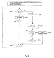
- Fig. 5 illustrates a detailed flow diagram of a DC balancing scheme similar to that illustrated in Fig. 4 in accordance with one embodiment of the present invention.
- isym represents the intermediate input symbol consisting of 8 bits of pixel color data and one bit of other data, CRC bits, digital audio data, auxiliary information or some combination.
- the term sym represents the 10 bit output symbol.
- the DC balancing scheme determines whether a blanking period has been detected as illustrated by diamond 60A. If the blanking period is detected, the isym [9:0] is input into the DC balancing scheme as illustrated by block 62A. The value of the stream weight W s is initialized to 0 and sym[9:0] is output as illustrated by blocks 64A and 74A respectively.
- the isym [8:0] is input into the DC balancing scheme as illustrated by block 76A.
- the output sym[9:0] is outputted as illustrated by block 74A.
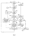
- Fig. 6 illustrates a detailed flow diagram of an alternate DC balancing scheme similar to that illustrated in Figs. 4 and 5 in accordance with one embodiment of the present invention.
- the DC balancing scheme determines whether a blanking period is detected as illustrated by diamond 60B. In one embodiment, this scheme can transition between two modes, initialed on the blanking period or not initialed on the blanking period as illustrated by diamond 61 B. If this scheme is initialed in a blanking period, the DC balancing scheme determines whether the last vsync transition was positive as illustrated by diamond 62B. If the last vsync transition was positive, the stream weight, W S , is initialized to 0 immediately after the last positive transition on vsync. In one embodiment, Ws and W P are initialized to zero.
- the DC balancing scheme may compute W P and updates W S as illustrated by block 66B.
- DC balancing scheme determines whether the sign of W S (or the sign of W I if computed) is greater than zero as illustrated by diamond 68B. In one embodiment, if the scheme is not initialized in the blanking period as illustrated by diamond 61B, then blocks 62B, 64B and 66B are optional and may be skipped. If Sign ⁇ W S ⁇ (or Sign ⁇ W I ⁇ ) is less than zero (i.e. the sign is positive) then SYM [9:0] is a positive bias blanking code word specified by IN [1:0] provided previously as illustrated by block 70B. If however, Sign ⁇ W S ⁇ (or Sign ⁇ W I ⁇ ) is greater than zero (i.e.
- SYM [9:0] negative bias blanking code word specified by IN [1:0] provided previously as illustrated by block 72B.
- the DC balancing scheme then outputs the sym [9:0] as indicated by block 74B.
- the isym [8:0] is input into the DC balancing scheme as illustrated by block 76B.
- the output sym[9:0] is outputted as illustrated by block 74B.
Landscapes
- Physics & Mathematics (AREA)
- Spectroscopy & Molecular Physics (AREA)
- Engineering & Computer Science (AREA)
- Computer Networks & Wireless Communication (AREA)
- Signal Processing (AREA)
- Compression, Expansion, Code Conversion, And Decoders (AREA)
- Compression Or Coding Systems Of Tv Signals (AREA)
Abstract
Description
| IN[1:0] | Positive Bias blanking period Codeword [MSB:LSB] | Negative Bias blanking period Codeword [MSB:LSB] |
| 00 | 0000011111 | 0000011111 |
| 01 | 0000111111 | 0000001111 |
| 10 | 0001111111 | 0000000111 |
| 11 | 0011111111 | 0000000011 |
Claims (27)
- A method of encoding video comprising:concatenating at least one data bit onto at least one component of input data; andbalancing said at least one component and said at least one data bit.
- The method of Claim 1, including communicating said balanced component and said concatenated data bit.
- The method of Claim 1, including computing at least one CRC bit and concatenating said at least one CRC bit onto said at least one component.
- The method of Claim 1, including concatenating audio data onto said at least one component.
- The method of Claim 1, including concatenating auxiliary data onto said at least one component.
- The method of Claim 1, including concatenating status information onto said at least one component.
- The method of Claim 1, including detecting pixel errors.
- The method of Claim 7, further including compensating for said detected pixel errors.
- The method of Claim 8, wherein compensating comprises keeping a last pixel value.
- The method of Claim 8, wherein compensating comprises averaging adjacent pixel values.
- The method of Claim 8, wherein compensating comprises interpolating between prior and next non-errored pixel values.
- A method of encoding video comprising:receiving input data;splitting said input data into at least two components; andconcatenating at least one data bit onto at least one of said components.
- The method of Claim 12, wherein splitting said input data includes splitting said input data into color pixels.
- The method of Claim 13, wherein splitting said input data includes splitting said input data into eight bit color pixels.
- The method of Claim 12, including computing at least one CRC bit.
- The method of Claim 15, including concatenating said at least one CRC bit onto said at least one of said components.
- The method of Claim 12, including concatenating audio data onto said at least one of said components.
- The method of Claim 12, including concatenating auxiliary information onto said at least one of said components.
- The method of Claim 12, including concatenating status information onto said at least one of said components.
- The method of Claim 12, including DC balancing said components and said concatenated data bit.
- The method of Claim 12, including communicating said components having said additional data bit to at least one channel.
- A method of encoding video comprising:registering a received input pixel;splitting said input pixel into a plurality of color components;concatenating at least one data bit onto said plurality of color components; andbalancing said color components and said concatenated data bit.
- The method of Claim 22, including communicating said balanced color components and said at least one data bit to at least one communication channel.
- The method of Claim 22, including computing at least one CRC bit and concatenating said at least one CRC bit onto said plurality of color components.
- The method of Claim 22, including concatenating audio data onto said plurality of color components.
- The method of Claim 22, including concatenating auxiliary data onto said plurality of color components.
- The method of Claim 22, including concatenating status information onto said plurality of color components.
Applications Claiming Priority (20)
| Application Number | Priority Date | Filing Date | Title |
|---|---|---|---|
| US26379201P | 2001-01-24 | 2001-01-24 | |
| US263792P | 2001-01-24 | ||
| US26884001P | 2001-02-14 | 2001-02-14 | |
| US268840P | 2001-02-14 | ||
| US31315701P | 2001-08-16 | 2001-08-16 | |
| US313157P | 2001-08-16 | ||
| US31344101P | 2001-08-17 | 2001-08-17 | |
| US313441P | 2001-08-17 | ||
| US31361001P | 2001-08-20 | 2001-08-20 | |
| US313610P | 2001-08-20 | ||
| US31413701P | 2001-08-21 | 2001-08-21 | |
| US314137P | 2001-08-21 | ||
| US09/951,671 US7356051B2 (en) | 2001-01-24 | 2001-09-12 | Digital visual interface with audio and auxiliary data cross reference to related applications |
| US951289 | 2001-09-12 | ||
| US951671 | 2001-09-12 | ||
| US09/951,289 US20020097869A1 (en) | 2001-01-24 | 2001-09-12 | System and method for increased data capacity of a digital video link |
| US34414 | 2001-12-27 | ||
| US34383 | 2001-12-27 | ||
| US10/034,383 US20030070132A1 (en) | 2001-08-16 | 2001-12-27 | Flexible video encoding scheme supporting audio and auxiliary information |
| US10/034,414 US8798166B2 (en) | 2001-08-17 | 2001-12-27 | Video encoding scheme supporting the transport of audio and auxiliary information |
Publications (2)
| Publication Number | Publication Date |
|---|---|
| EP1231751A2 true EP1231751A2 (en) | 2002-08-14 |
| EP1231751A3 EP1231751A3 (en) | 2006-08-02 |
Family
ID=27580760
Family Applications (2)
| Application Number | Title | Priority Date | Filing Date |
|---|---|---|---|
| EP02250463A Withdrawn EP1231752A3 (en) | 2001-01-24 | 2002-01-23 | Video encoding scheme supporting the transport of audio and auxiliary information |
| EP02250462A Withdrawn EP1231751A3 (en) | 2001-01-24 | 2002-01-23 | Flexible video encoding scheme supporting audio and auxiliary information |
Family Applications Before (1)
| Application Number | Title | Priority Date | Filing Date |
|---|---|---|---|
| EP02250463A Withdrawn EP1231752A3 (en) | 2001-01-24 | 2002-01-23 | Video encoding scheme supporting the transport of audio and auxiliary information |
Country Status (1)
| Country | Link |
|---|---|
| EP (2) | EP1231752A3 (en) |
Family Cites Families (2)
| Publication number | Priority date | Publication date | Assignee | Title |
|---|---|---|---|---|
| US5835498A (en) * | 1995-10-05 | 1998-11-10 | Silicon Image, Inc. | System and method for sending multiple data signals over a serial link |
| US5974464A (en) * | 1995-10-06 | 1999-10-26 | Silicon Image, Inc. | System for high speed serial video signal transmission using DC-balanced coding |
-
2002
- 2002-01-23 EP EP02250463A patent/EP1231752A3/en not_active Withdrawn
- 2002-01-23 EP EP02250462A patent/EP1231751A3/en not_active Withdrawn
Also Published As
| Publication number | Publication date |
|---|---|
| EP1231751A3 (en) | 2006-08-02 |
| EP1231752A2 (en) | 2002-08-14 |
| EP1231752A3 (en) | 2006-11-15 |
Similar Documents
| Publication | Publication Date | Title |
|---|---|---|
| US8378860B2 (en) | Method and system for generating high definition multimedia interface (HDMI) codewords using a TMDS encoder/decoder | |
| JP3644504B2 (en) | Digital signal transmitter | |
| US7230650B2 (en) | Data transmission method, data receiving method, video data transmission apparatus and video data receiving apparatus | |
| US6897793B1 (en) | Method and apparatus for run length limited TMDS-like encoding of data | |
| US8798189B2 (en) | Digital video physical layer using a multi-level data code | |
| US6710910B2 (en) | Optical amplitude demodulator | |
| JPH11506289A (en) | Block coding for digital video transmission | |
| US20020054420A1 (en) | Optical amplitude modulator | |
| JP2003528516A (en) | Selective data compression of digital pixel information | |
| US20030070132A1 (en) | Flexible video encoding scheme supporting audio and auxiliary information | |
| US6903780B2 (en) | Method of expanding high-speed serial video data providing compatibility with a class of DVI receivers | |
| US7573534B2 (en) | Digital display appliance and method for outputting video data | |
| KR100733747B1 (en) | Data transmission method, data transmission circuit, output circuit, input circuit, semiconductor device, and electronic device | |
| US7363575B2 (en) | Method and system for TERC4 decoding using minimum distance rule in high definition multimedia interface (HDMI) specifications | |
| US6912008B2 (en) | Method of adding data to a data communication link while retaining backward compatibility | |
| KR20070024296A (en) | Digital Multimedia Data Transceiver with Digital Multimedia Interface | |
| CN109389958B (en) | Display panel driving method and driving device and display device | |
| US6633243B2 (en) | Method of encoding video data for serial transmission | |
| US9872035B2 (en) | System and method for transcoding data | |
| US8798166B2 (en) | Video encoding scheme supporting the transport of audio and auxiliary information | |
| US6754240B1 (en) | Format for an optical data link | |
| CN111526318A (en) | Type-C interface and signal conversion method | |
| US20010036226A1 (en) | Method and apparatus for transmitting data from an analogue modem to a digital modem through an analogue channel | |
| KR101605181B1 (en) | Method for correction of error code included in control signal of hdmi/mhl | |
| US11315474B2 (en) | Method and device for driving display panel, and display device |
Legal Events
| Date | Code | Title | Description |
|---|---|---|---|
| PUAI | Public reference made under article 153(3) epc to a published international application that has entered the european phase |
Free format text: ORIGINAL CODE: 0009012 |
|
| AK | Designated contracting states |
Kind code of ref document: A2 Designated state(s): AT BE CH CY DE DK ES FI FR GB GR IE IT LI LU MC NL PT SE TR |
|
| AX | Request for extension of the european patent |
Free format text: AL;LT;LV;MK;RO;SI |
|
| PUAL | Search report despatched |
Free format text: ORIGINAL CODE: 0009013 |
|
| AK | Designated contracting states |
Kind code of ref document: A3 Designated state(s): AT BE CH CY DE DK ES FI FR GB GR IE IT LI LU MC NL PT SE TR |
|
| AX | Request for extension of the european patent |
Extension state: AL LT LV MK RO SI |
|
| RIC1 | Information provided on ipc code assigned before grant |
Ipc: H04N 7/52 20060101ALI20060627BHEP Ipc: H04L 25/49 20060101AFI20020624BHEP |
|
| 17P | Request for examination filed |
Effective date: 20070202 |
|
| AKX | Designation fees paid |
Designated state(s): DE FR GB |
|
| RAP1 | Party data changed (applicant data changed or rights of an application transferred) |
Owner name: BROADCOM CORPORATION |
|
| 17Q | First examination report despatched |
Effective date: 20080508 |
|
| STAA | Information on the status of an ep patent application or granted ep patent |
Free format text: STATUS: THE APPLICATION IS DEEMED TO BE WITHDRAWN |
|
| 18D | Application deemed to be withdrawn |
Effective date: 20110802 |