EP1231446A2 - Heat exchanger for fuel cell system - Google Patents
Heat exchanger for fuel cell system Download PDFInfo
- Publication number
- EP1231446A2 EP1231446A2 EP02002397A EP02002397A EP1231446A2 EP 1231446 A2 EP1231446 A2 EP 1231446A2 EP 02002397 A EP02002397 A EP 02002397A EP 02002397 A EP02002397 A EP 02002397A EP 1231446 A2 EP1231446 A2 EP 1231446A2
- Authority
- EP
- European Patent Office
- Prior art keywords
- passage
- cooling medium
- transfer tube
- heat transfer
- gas
- Prior art date
- Legal status (The legal status is an assumption and is not a legal conclusion. Google has not performed a legal analysis and makes no representation as to the accuracy of the status listed.)
- Granted
Links
- 239000000446 fuel Substances 0.000 title claims description 15
- 238000012546 transfer Methods 0.000 claims abstract description 77
- 239000002826 coolant Substances 0.000 claims abstract description 63
- 238000011144 upstream manufacturing Methods 0.000 claims abstract description 42
- 239000003054 catalyst Substances 0.000 claims description 16
- 238000010030 laminating Methods 0.000 claims description 6
- 230000000717 retained effect Effects 0.000 claims description 2
- 238000009826 distribution Methods 0.000 abstract description 30
- 239000007789 gas Substances 0.000 description 140
- 239000000110 cooling liquid Substances 0.000 description 75
- 229910052751 metal Inorganic materials 0.000 description 46
- 239000002184 metal Substances 0.000 description 46
- UGFAIRIUMAVXCW-UHFFFAOYSA-N Carbon monoxide Chemical compound [O+]#[C-] UGFAIRIUMAVXCW-UHFFFAOYSA-N 0.000 description 20
- 229910002091 carbon monoxide Inorganic materials 0.000 description 20
- 238000007373 indentation Methods 0.000 description 17
- 238000006243 chemical reaction Methods 0.000 description 14
- 238000000638 solvent extraction Methods 0.000 description 11
- 230000003197 catalytic effect Effects 0.000 description 10
- 239000002131 composite material Substances 0.000 description 10
- 239000007800 oxidant agent Substances 0.000 description 7
- 238000002474 experimental method Methods 0.000 description 6
- 238000000605 extraction Methods 0.000 description 6
- 229910000679 solder Inorganic materials 0.000 description 6
- 238000005476 soldering Methods 0.000 description 6
- 230000000052 comparative effect Effects 0.000 description 5
- 238000001816 cooling Methods 0.000 description 5
- 230000007423 decrease Effects 0.000 description 5
- 230000000694 effects Effects 0.000 description 5
- 239000010935 stainless steel Substances 0.000 description 5
- 229910001220 stainless steel Inorganic materials 0.000 description 5
- 238000005259 measurement Methods 0.000 description 4
- 230000003014 reinforcing effect Effects 0.000 description 4
- LYCAIKOWRPUZTN-UHFFFAOYSA-N Ethylene glycol Chemical compound OCCO LYCAIKOWRPUZTN-UHFFFAOYSA-N 0.000 description 3
- QVGXLLKOCUKJST-UHFFFAOYSA-N atomic oxygen Chemical compound [O] QVGXLLKOCUKJST-UHFFFAOYSA-N 0.000 description 3
- 238000006555 catalytic reaction Methods 0.000 description 3
- 238000004519 manufacturing process Methods 0.000 description 3
- 239000001301 oxygen Substances 0.000 description 3
- 229910052760 oxygen Inorganic materials 0.000 description 3
- UFHFLCQGNIYNRP-UHFFFAOYSA-N Hydrogen Chemical compound [H][H] UFHFLCQGNIYNRP-UHFFFAOYSA-N 0.000 description 2
- 239000011888 foil Substances 0.000 description 2
- 238000010438 heat treatment Methods 0.000 description 2
- 239000001257 hydrogen Substances 0.000 description 2
- 229910052739 hydrogen Inorganic materials 0.000 description 2
- 238000000034 method Methods 0.000 description 2
- 238000002156 mixing Methods 0.000 description 2
- 230000008569 process Effects 0.000 description 2
- 239000002356 single layer Substances 0.000 description 2
- 229910000838 Al alloy Inorganic materials 0.000 description 1
- 238000010521 absorption reaction Methods 0.000 description 1
- 238000005253 cladding Methods 0.000 description 1
- 239000011248 coating agent Substances 0.000 description 1
- 238000000576 coating method Methods 0.000 description 1
- 238000010276 construction Methods 0.000 description 1
- 239000000112 cooling gas Substances 0.000 description 1
- 230000003247 decreasing effect Effects 0.000 description 1
- 238000003487 electrochemical reaction Methods 0.000 description 1
- 239000010410 layer Substances 0.000 description 1
- 238000012423 maintenance Methods 0.000 description 1
- 238000012986 modification Methods 0.000 description 1
- 230000004048 modification Effects 0.000 description 1
- 230000001590 oxidative effect Effects 0.000 description 1
- 238000005192 partition Methods 0.000 description 1
- 230000002093 peripheral effect Effects 0.000 description 1
- 238000007747 plating Methods 0.000 description 1
- 238000010248 power generation Methods 0.000 description 1
- 230000009467 reduction Effects 0.000 description 1
- 238000002407 reforming Methods 0.000 description 1
- 230000004044 response Effects 0.000 description 1
- 238000004088 simulation Methods 0.000 description 1
- 231100000331 toxic Toxicity 0.000 description 1
- 230000002588 toxic effect Effects 0.000 description 1
Images


Classifications
-
- H—ELECTRICITY
- H01—ELECTRIC ELEMENTS
- H01M—PROCESSES OR MEANS, e.g. BATTERIES, FOR THE DIRECT CONVERSION OF CHEMICAL ENERGY INTO ELECTRICAL ENERGY
- H01M8/00—Fuel cells; Manufacture thereof
- H01M8/04—Auxiliary arrangements, e.g. for control of pressure or for circulation of fluids
- H01M8/04007—Auxiliary arrangements, e.g. for control of pressure or for circulation of fluids related to heat exchange
- H01M8/04067—Heat exchange or temperature measuring elements, thermal insulation, e.g. heat pipes, heat pumps, fins
-
- F—MECHANICAL ENGINEERING; LIGHTING; HEATING; WEAPONS; BLASTING
- F28—HEAT EXCHANGE IN GENERAL
- F28D—HEAT-EXCHANGE APPARATUS, NOT PROVIDED FOR IN ANOTHER SUBCLASS, IN WHICH THE HEAT-EXCHANGE MEDIA DO NOT COME INTO DIRECT CONTACT
- F28D9/00—Heat-exchange apparatus having stationary plate-like or laminated conduit assemblies for both heat-exchange media, the media being in contact with different sides of a conduit wall
- F28D9/0031—Heat-exchange apparatus having stationary plate-like or laminated conduit assemblies for both heat-exchange media, the media being in contact with different sides of a conduit wall the conduits for one heat-exchange medium being formed by paired plates touching each other
- F28D9/0043—Heat-exchange apparatus having stationary plate-like or laminated conduit assemblies for both heat-exchange media, the media being in contact with different sides of a conduit wall the conduits for one heat-exchange medium being formed by paired plates touching each other the plates having openings therein for circulation of at least one heat-exchange medium from one conduit to another
- F28D9/0056—Heat-exchange apparatus having stationary plate-like or laminated conduit assemblies for both heat-exchange media, the media being in contact with different sides of a conduit wall the conduits for one heat-exchange medium being formed by paired plates touching each other the plates having openings therein for circulation of at least one heat-exchange medium from one conduit to another with U-flow or serpentine-flow inside conduits; with centrally arranged openings on the plates
-
- F—MECHANICAL ENGINEERING; LIGHTING; HEATING; WEAPONS; BLASTING
- F28—HEAT EXCHANGE IN GENERAL
- F28D—HEAT-EXCHANGE APPARATUS, NOT PROVIDED FOR IN ANOTHER SUBCLASS, IN WHICH THE HEAT-EXCHANGE MEDIA DO NOT COME INTO DIRECT CONTACT
- F28D9/00—Heat-exchange apparatus having stationary plate-like or laminated conduit assemblies for both heat-exchange media, the media being in contact with different sides of a conduit wall
- F28D9/0062—Heat-exchange apparatus having stationary plate-like or laminated conduit assemblies for both heat-exchange media, the media being in contact with different sides of a conduit wall the conduits for one heat-exchange medium being formed by spaced plates with inserted elements
- F28D9/0075—Heat-exchange apparatus having stationary plate-like or laminated conduit assemblies for both heat-exchange media, the media being in contact with different sides of a conduit wall the conduits for one heat-exchange medium being formed by spaced plates with inserted elements the plates having openings therein for circulation of the heat-exchange medium from one conduit to another
-
- F—MECHANICAL ENGINEERING; LIGHTING; HEATING; WEAPONS; BLASTING
- F28—HEAT EXCHANGE IN GENERAL
- F28F—DETAILS OF HEAT-EXCHANGE AND HEAT-TRANSFER APPARATUS, OF GENERAL APPLICATION
- F28F13/00—Arrangements for modifying heat-transfer, e.g. increasing, decreasing
- F28F13/06—Arrangements for modifying heat-transfer, e.g. increasing, decreasing by affecting the pattern of flow of the heat-exchange media
- F28F13/08—Arrangements for modifying heat-transfer, e.g. increasing, decreasing by affecting the pattern of flow of the heat-exchange media by varying the cross-section of the flow channels
-
- F—MECHANICAL ENGINEERING; LIGHTING; HEATING; WEAPONS; BLASTING
- F28—HEAT EXCHANGE IN GENERAL
- F28F—DETAILS OF HEAT-EXCHANGE AND HEAT-TRANSFER APPARATUS, OF GENERAL APPLICATION
- F28F3/00—Plate-like or laminated elements; Assemblies of plate-like or laminated elements
- F28F3/02—Elements or assemblies thereof with means for increasing heat-transfer area, e.g. with fins, with recesses, with corrugations
- F28F3/025—Elements or assemblies thereof with means for increasing heat-transfer area, e.g. with fins, with recesses, with corrugations the means being corrugated, plate-like elements
-
- F—MECHANICAL ENGINEERING; LIGHTING; HEATING; WEAPONS; BLASTING
- F28—HEAT EXCHANGE IN GENERAL
- F28F—DETAILS OF HEAT-EXCHANGE AND HEAT-TRANSFER APPARATUS, OF GENERAL APPLICATION
- F28F3/00—Plate-like or laminated elements; Assemblies of plate-like or laminated elements
- F28F3/02—Elements or assemblies thereof with means for increasing heat-transfer area, e.g. with fins, with recesses, with corrugations
- F28F3/04—Elements or assemblies thereof with means for increasing heat-transfer area, e.g. with fins, with recesses, with corrugations the means being integral with the element
-
- H—ELECTRICITY
- H01—ELECTRIC ELEMENTS
- H01M—PROCESSES OR MEANS, e.g. BATTERIES, FOR THE DIRECT CONVERSION OF CHEMICAL ENERGY INTO ELECTRICAL ENERGY
- H01M8/00—Fuel cells; Manufacture thereof
- H01M8/04—Auxiliary arrangements, e.g. for control of pressure or for circulation of fluids
- H01M8/04007—Auxiliary arrangements, e.g. for control of pressure or for circulation of fluids related to heat exchange
-
- F—MECHANICAL ENGINEERING; LIGHTING; HEATING; WEAPONS; BLASTING
- F28—HEAT EXCHANGE IN GENERAL
- F28D—HEAT-EXCHANGE APPARATUS, NOT PROVIDED FOR IN ANOTHER SUBCLASS, IN WHICH THE HEAT-EXCHANGE MEDIA DO NOT COME INTO DIRECT CONTACT
- F28D21/00—Heat-exchange apparatus not covered by any of the groups F28D1/00 - F28D20/00
- F28D2021/0019—Other heat exchangers for particular applications; Heat exchange systems not otherwise provided for
- F28D2021/0043—Other heat exchangers for particular applications; Heat exchange systems not otherwise provided for for fuel cells
-
- F—MECHANICAL ENGINEERING; LIGHTING; HEATING; WEAPONS; BLASTING
- F28—HEAT EXCHANGE IN GENERAL
- F28F—DETAILS OF HEAT-EXCHANGE AND HEAT-TRANSFER APPARATUS, OF GENERAL APPLICATION
- F28F2250/00—Arrangements for modifying the flow of the heat exchange media, e.g. flow guiding means; Particular flow patterns
- F28F2250/10—Particular pattern of flow of the heat exchange media
- F28F2250/102—Particular pattern of flow of the heat exchange media with change of flow direction
-
- H—ELECTRICITY
- H01—ELECTRIC ELEMENTS
- H01M—PROCESSES OR MEANS, e.g. BATTERIES, FOR THE DIRECT CONVERSION OF CHEMICAL ENERGY INTO ELECTRICAL ENERGY
- H01M8/00—Fuel cells; Manufacture thereof
- H01M8/06—Combination of fuel cells with means for production of reactants or for treatment of residues
- H01M8/0606—Combination of fuel cells with means for production of reactants or for treatment of residues with means for production of gaseous reactants
- H01M8/0612—Combination of fuel cells with means for production of reactants or for treatment of residues with means for production of gaseous reactants from carbon-containing material
-
- Y—GENERAL TAGGING OF NEW TECHNOLOGICAL DEVELOPMENTS; GENERAL TAGGING OF CROSS-SECTIONAL TECHNOLOGIES SPANNING OVER SEVERAL SECTIONS OF THE IPC; TECHNICAL SUBJECTS COVERED BY FORMER USPC CROSS-REFERENCE ART COLLECTIONS [XRACs] AND DIGESTS
- Y02—TECHNOLOGIES OR APPLICATIONS FOR MITIGATION OR ADAPTATION AGAINST CLIMATE CHANGE
- Y02E—REDUCTION OF GREENHOUSE GAS [GHG] EMISSIONS, RELATED TO ENERGY GENERATION, TRANSMISSION OR DISTRIBUTION
- Y02E60/00—Enabling technologies; Technologies with a potential or indirect contribution to GHG emissions mitigation
- Y02E60/30—Hydrogen technology
- Y02E60/50—Fuel cells
Definitions
- This invention relates to a heat exchanger for a gas reformed from fuel in a fuel cell system.
- JPA2000 - 315508 An example of a fuel cell system is disclosed in JPA2000 - 315508 which generates power by electro-chemical reactions of oxygen with a reformate gas produced by reforming fuel into a hydrogen-rich gas.
- Carbon monoxide is contained in the reformate gas produced by the reformer which reforms fuel. Catalytic reactions in a carbon monoxide oxidizer are used in order to remove carbon monoxide before the reformate gas is supplied to the fuel cell due to the fact that the presence of carbon monoxide reduces power generation efficiency.
- the temperature of the reformate gas immediately after being produced in the reformer is approximately 300 °C. Consequently, before the gas is supplied to the carbon monoxide oxidizer, it is required to reduce the temperature to approximately 100 °C by passing the gas through a heat exchanger. Catalytic reactions performed in the carbon monoxide oxidizer are performed efficiently only in a fixed temperature range about 100 °C. The efficiency of reactions is reduced when the temperature of the reformate gas is either higher or lower than this fixed temperature range.
- the invention provides with a heat exchanger for use in a fuel cell system.
- the heat exchanger comprises heat transfer tube elements having an flat passage allowing flow of a cooling medium therein, outer fins retained between adjacent the heat transfer tube elements allowing flow of a gas there through and a core formed by laminating the heat transfer tube elements and the outer fins in order.
- the gas flows through the outer fins in a direction orthogonal to the direction of cooling medium flow which flows in the passage in each heat transfer tube element, and a passage in at least a section of the passage for cooling medium provided in each heat transfer tube element comprises a large passage and a small passage group disposed in parallel, the large passage having a large width and being provided upstream to the core with respect to the direction of gas flow, and the small passage group comprising a plurality of small passages being narrower than the large passage and being provided downstream of the core with respect to the direction of gas flow.
- Fig. 1 to Fig. 12 show a fuel cell heat exchanger according to this invention.
- Fig. 1 to Fig. 5 show the actual structure of the heat exchanger and
- Fig. 6 to Fig. 12 show a simplified version thereof.
- the heat exchanger 4 is used in order to cool a reformate gas transferred to a carbon monoxide oxidizer in a fuel cell system.
- the core 12a of the heat exchanger 4 is formed by cross laminating a plurality of heat transfer tube elements 17 with a composite fin 18.
- the heat transfer tube elements 17 have a passage allowing flow of a cooling liquid as a cooling medium in an inner section.
- the composite fins 18 comprise an outer fin respectively disposed between adjacent heat transfer tube elements 17.
- each composite fin 18 retains a single-layer plate fin 20 between a pair of corrugated fins 19, 19 and allows flow of the reformate gas in the inner section of the composite fin 18.
- the cooling liquid flows in a direction which is orthogonal to the flow of the gas. It may be possible to provide a single corrugated fin 19 instead of the composite fin 18.
- a pair of side plates 21a, 21b is disposed on both vertical ends of the core 12a. Only a single corrugated fin 19 is disposed between the heat transfer tube elements 17 on the inner side of each side plate 21a, 21b.
- each heat transfer tube element 17 superimposes a pair of plates comprising a first metal plate 22 and a second metal plate 23 so that the indentation of the plates are facing.
- the plates 22, 23 are soldered together to make watertight contact.
- An flat passage 24 is formed in the inner section of each heat transfer tube element 17 to allow flow of cooling liquid.
- a pair of deep elongated indentations 25, 25 (refer to Fig. 6 and Fig. 11) in a transverse direction (a direction orthogonal to the direction of flow of the cooling liquid) are provided on both ends of each metal plate 22, 23.
- a shallow indentation 26 is provided on a central section in order to connect the deep indentations 25, 25 on both sides. The shallow indentation 26 is adapted to be more shallow than the deep indentations 25, 25.
- Each heat transferring tube element 17 respectively superimposes a first metal plate 22 on a second metal plate 23 so that the respective indentations, namely the deep indentations 25 and the shallow indentations 26 are facing.
- a first tank 27 and a second tank 28 are formed in a section of each deep indentation 25 and a passage 24 is formed in a section of the shallow indentation 26.
- the passage 24 connects the first tank 27 and the second tank 28 in order to allow flow of cooling liquid therebetween.
- This invention is characterized by the structure of the passage 24.
- multiple projections 29, 29 are formed in a fixed transverse range from one end (the front of Figs. 1, 3, 6, 7, 9, 10, and 12, the lower end of Figs. 2 and 11, and the left end of Figs, 4, 5, and 8) to the other end.
- This direction represents the direction of gas flow.
- the projections 29, 29 are provided on the bottom face of the shallow indentation 26 which forms the passage 24.
- the projections 29 are provided in a range representing approximately 90% of the overall transverse length and most preferably, in 60 to 80% of the transverse length of the indentation 26.
- the passage 24 comprises a large passage 31 with a large width in the region provided with projections 29, 29.
- each projection 29, 29 is soldered so that when the indentations of the first and second metal plates 22, 23 are assembled, the peripheral edges of the metal plates 22, 23 are facing.
- the contact sections of each projection 29 form a reinforcing section 45.
- the lower face of the passage 24 is formed substantially as a flat face in the remaining section of the passage 24, that is to say, in a range of more than 10% of the overall transverse length, and most preferably in a range of 20 - 40% and where projections 29 are not provided.
- a corrugated inner fin 30 is disposed so that the direction of the waveform corresponds with the transverse direction of the passage 24.
- This region comprises a small passage group 33 formed from a plurality of small narrow passages 32, 32.
- a projection 46 is formed on the end of the shallow indentation 26 provided in the metal plate 22 (or 23).
- the core 12a provides an inlet tank 34 which is formed by connecting the first tanks 27 on one end of the laminated heat transfer tube elements 17.
- the second tanks 28 on the other side of each heat transfer tube element 17 are interconnected to form an outlet tank 35.
- an elongated transverse through hole 36 is formed in the central section of each deep indentation 25, 25 of the upper first metal plate 22, as also shown in Fig. 12, an outward cylindrical section 37 projects towards the periphery of the through hole 36.
- an elongated transverse through hole 36 is formed in the central section of each deep indentation 25, 25 of the lower second metal plate 23.
- An inward cylindrical section 38 projects towards the periphery of the through hole 36.
- the outward cylindrical sections 37 are engaged to the inner side of each inward cylindrical section 38.
- the outward cylindrical sections 37 are provided on the first metal plate 22 comprising the upper heat transfer tube elements 17 and the inward cylindrical sections 38 are provided on the second metal plate 23 comprising the lower heat transfer tube element 17
- a core 12a is formed by sequentially laminating a required number of heat transfer tube elements 17.
- inlet and outlet through holes 39, 40 are formed at separate positions along a substantially diagonal line of the heat transfer tube elements 17 on the upper side-plate 21a of the core 12a.
- Core 12a is laminated on the lower side of the upper side-plate 21a and outward cylindrical sections 85 are fitted into the inner side of the inlet and outlet through holes 39, 40.
- the outward cylindrical sections 85 are formed on the periphery of the circular through hole provided on the uppermost single-layer first metal plate 22 instead of the elongated through hole 36
- a pair of elongated transverse protrusions 41, 41 are provided on both ends of the side-plate 21b on the lower end of the core 12a and these protrusions 41, 41 are engaged in the through holes 36, 36 provided on the lowermost second metal plate 23. This arrangement allows the lower end of each inlet and outlet tank 34, 35 to be covered in a water-tight manner by the lower side-plate 21b.
- the heat exchanger 4 of this invention is assembled from the first and second metal plates 22, 23, the inner fin 30, the composite fin 18, the pair of side-plates 21a, 21b, the cooling medium transfer pipe 15, the cooling medium extraction pipe 16 and the connecting members 42, 42.
- the connecting members 42, 42 connect the end of the cooling medium transfer pipe 15 and the cooling medium extraction pipe 16 with the upper surface of the upper side-plate 21a.
- the assembled product is heated in a heating furnace and each member 22, 23, 30, 18, 21a, 21b, 15, 16, 42 is engaged by soldering.
- the cooling medium transfer pipe 15 and cooling medium extraction pipe 16 connect through the inlet tank 34 and the outlet tank 35 through the inlet through hole 39 and the outlet through hole 40 which are respectively provided in the upper side-plate 21a.
- the first and second metal plates 22, 23 which comprise each heat transfer tube element 17 are formed by plating layers of soldering containing large amounts of Ni onto both surfaces of a core member such as stainless steel plate.
- a core member such as stainless steel plate.
- metal plates 22, 23 simply comprising stainless steel plate it is possible to coat solder of a paste-like consistency containing large amounts of Ni onto both surfaces of each metal plate 22, 23 and to sandwich solder foil between an outer fin and each surface.
- Each metal plate 22, 23 can also be formed by cladding solder (for example, 4004 , 4343 ) onto an aluminum alloy (for example 3003 ).
- a rectangular projecting piece 43 is formed on both the gas inlet and gas outlet end of the upper side-plate 21a.
- the projecting piece 43 forms a connecting section with piping (not shown) in order to transfer gas to the core 12a by assembly with a section of the case 44 which retains the core 12a.
- the heat exchanger 4 in a fuel cell system as described above is disposed upstream of the carbon monoxide oxidizer or the catalytic heat exchanger.
- High-temperature reformate gas produced by a reformer flow in the direction ⁇ of the arrow in Figs. 2, 4, 6, 11 in the inner section of the composite fin 18 between each heat transfer tube element 17 comprising the core 12a.
- Relatively low-temperature cooling liquid is transferred to the inlet tank 34 from the cooling medium transfer pipe 15.
- the cooling liquid transferred to the inlet tank 34 reaches the outlet tank 35 by flowing in the direction ⁇ of the arrow in Figs. 6 and 11 in the plurality of passages provided in each heat transfer tube element 17. During this period, heat exchange is performed with the gas flowing in the composite fin 18.
- the cooling liquid which reaches the outlet tank 35 is extracted to the outside through a cooling liquid extraction pipe 16 and returns to the inlet tank 34 once again after being cooled in another heat exchanger.
- the gas passing through the composite fin 18 of the core 12a is cooled by heat exchange.
- the passage 24 in which the cooling liquid flows comprises a large passage 31 having a large width and a group of small passages 33 with a small width, it is possible to reduce non-uniformity in a transverse orientation of the temperature distribution of the gas flowing through the core 12a to a level which is negligible for practical purposes.
- FIG. 1 show the results of a simulation of the temperature distribution in the core 12a of the gas passing through the composite fin 18 between each heat transfer tube elements 17, 17 (refer to Fig. 1) and the cooling liquid passing through the passage 24 provided in each heat transfer tube element 17.
- the temperature distribution of the gas is shown in the figure by the section bounded by a solid line and the temperature distribution of the cooling liquid is shown by the section bounded by a broken line.
- the X -axis in the figure corresponds with the direction ⁇ of gas flow and the Y -axis corresponds with the direction ⁇ of flow of the cooling liquid.
- Fig. 13 shows the situation in which an inner fin 30 is not provided in the passage 24 allowing flow of the cooling liquid in each heat transfer tube element 17 and the whole of the passage 24 is adapted to form a large passage 31.
- Fig. 14 shows the situation in which an inner fin 30 is provided in the entire passage 24 and the entire passage 24 is adapted to form a group of small passages 33.
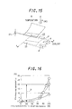
- Fig. 15 shows the present invention in which the upper section of the passage 24 in the direction ⁇ of gas flow is adapted to form a large passage 31 and the lower section forms a group of small passages 33.
- the temperature distribution of the cooling liquid as shown in Fig. 13 will be considered with respect to the cross-sectional area which is orthogonal to the direction ⁇ of flow of cooling liquid. Since the cooling liquid undergoes mixing in the passage 24 across the entire cross-sectional area (transverse direction), the temperature of the cooling liquid takes substantially the same value across the cross-sectional area.
- the cooling liquid performs heat exchange with the gas while flowing in direction ⁇ in the Fig. 13 and the temperature thereof increases uniformly in downstream sections as a result of absorption of heat from the gas.
- the gas radiates heat into the cooling liquid as a result of heat exchange during flow in direction ⁇ in the figure after entering from the inlet.
- the gas temperature falls along the downstream section.
- the gas temperature falls in response to the temperature of the cooling liquid in each section performing heat exchange. That is to say, when the temperature of the cooling liquid performing heat exchange is relatively low, the decrease in the gas temperature increases. Conversely, when the temperature of the cooling liquid performing heat exchange is relatively high, the decrease in the gas temperature is reduced.
- ⁇ t1 the temperature differential of the gas with respect to the direction ⁇ of flow of the cooling liquid at the gas outlet takes a large value ⁇ t1 which means that the temperature distribution of the gas is not uniform.
- cooling liquid flowing downstream with respect to the gas flow flows in direction ⁇ at a relatively low temperature in comparison to the cooling liquid flowing upstream with respect to the gas flow.
- gas flowing downstream with respect to the flow of cooling liquid undergoes low levels of heat exchange due to the high temperature of the cooling liquid at the inlet.
- level of heat exchange increases due to the relatively low temperature of the cooling liquid in downstream sections in the direction of gas flow.
- the temperature differential ⁇ t2 in direction ⁇ at the gas outlet is small and the non-uniformity in the temperature distribution can be suppressed to a sufficient degree.
- the passage 24 is provided with: a large upstream passage 31 in the direction ⁇ of gas flow and a group of small passages 33 having a small width provided downstream with respect to the direction ⁇ of gas flow.
- the gas displays a non-uniform temperature distribution in upstream sections in direction ⁇ as a result of the same reason as that shown in Fig. 13, it is possible to suppress the temperature distribution in downstream sections to a low level due to the same reason as that shown in Fig. 14.
- the temperature differential ⁇ t3 of gas in the direction of flow of cooling liquid becomes slightly higher at the outlet of the core 12a in comparison to Fig. 14.
- the difference of ⁇ t3 and ⁇ t2 is not of a dimension which is negligible for practical purposes and consequently the non-uniformity in the temperature distribution of gas passing through the core 12a is suppressed to a level which is negligible for practical purposes.
- this invention adapts a section of the passage 24 to be a large passage 31, a reinforcing section 45 is formed by projecting a plurality of projections 29 in the large passage 31.
- a reinforcing section 45 is formed by projecting a plurality of projections 29 in the large passage 31.
- the strength of each heat transfer tube element 17 can be maintained without increasing in the size or weight of the heat exchanger as a result of increasing the thickness of the plate member comprising each heat transfer tube element 17 or providing a reinforcing sections on the outer section of each heat transfer tube element 17.
- the width d33 of the group of small passages 33 in the passage 24 is greater than or equal to 10% of the overall transverse width d24 of the passage 24 and preferably to 20 - 40%.
- the horizontal axis shows ratio of the large passage 31 in the entire passage 24 and the vertical axis shows the temperature differential on both ends in a direction orthogonal to the direction of flow of gas at the outlet of the heat exchanger.
- the sign ⁇ shows a reference value for a sufficient flow amount of cooling liquid, the sign ⁇ shows 50% of the reference value for the flow amount of cooling liquid and the sign ⁇ shows 25% thereof.
- a temperature distribution of reformate gas transferred into the catalytic heat exchanger or the carbon monoxide oxidizer in a range ⁇ 10 °C of a reference temperature represents a normal region in which problems do not arise with respect to reactions for reducing carbon monoxide in the reformate gas.
- the effect of reducing the temperature distribution at the gas outlet undergoes almost no variation even when the ratio of the small passage group 33 is greater than 40%, that is to say, the ratio of the large passage 31 is smaller than 60%.
- the ratio of the small passage group 33 in the passage 24 is 20 - 40% in this invention.
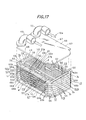
- This embodiment comprises a catalytic heat exchanger 10a which removes toxic carbon monoxide from the reformate gas and cools the heated gases.
- a core 54 is sequentially formed by laminating a plurality of heat transfer tube elements 51, 51 with corrugated outer fins 53 interposed therebetween.
- the heat transfer tube elements 51 comprise an flat passage allowing flow of cooling liquid (for example 100% ethylene glycol).
- a pair of first metal plates 52a, 52b is disposed on both side of the outer fin 53.
- the heat transfer tube elements 51 comprises a pair of corrugated inner fins 57a, 57b in a space on the inner side of the second metal plate 55 which forms a frame. Both surfaces of the fins 57a, 57b are sandwiched by a pair of partitioning plates 56, 56 comprising thin flat plates.
- the transverse dimensions of the inner fin 57a is smaller than the transverse dimensions of the other inner fin 57b.
- a projection 70 projecting inwardly is formed on the central section of one lateral section (the left side of Figs. 17 - 19, 21) of the second metal plate 55.
- One edge (the left edge of Figs. 17 - 19, 21) of each inner fin 57a, 57b is positioned by abutment with the distal end face of the projection 70.
- the spaces partitioned by the projection 70 between the inner left face of the second metal plate 55 and the left edge of the inner fins 57a, 57b comprise a first and second inner space 71, 72.
- the space partitioned between the right edge of the inner fins 57a, 57b and the opposite side of the inner face (the right side of Figs. 17 - 19, 21) of the second metal plate 55 comprises a third inner space 73.
- the partitioning plates 56 are provided with first and second through holes 58, 59 in sections respectively corresponding to the first and second inner spaces 71, 72 and an elongated third through hole 60 in a section corresponding to the third inner space 73.
- the partition 74 between the first and second through holes 58, 59 of each partitioning plate 56 is provided at a position corresponding to the projection 70 provided in each second metal plate 55.
- An oblong upstream cooling medium passage 61 and a downstream cooling medium passage 62 are provided in order to allow flow of cooling liquid between the inner fins 57a, 57b and both faces of the partitioning plates 56, 56.
- the upstream cooling medium passage 61 connects the first inner space 71 with the third inner space 73.
- the downstream cooling medium passage 62 connects the second inner space 72 with the third inner space 73.
- the upstream cooling medium passage 61 is provided upstream of the core 54 with respect to the direction ⁇ of gas flow.
- the upstream cooling medium passage 61 has transverse dimensions W61 in a direction of gas flow of 25 - 30mm.
- the transverse dimensions W57a of one inner fin 57a provided in the upstream cooling medium passage 61 are smaller by a predetermined amount than the transverse dimensions W61 of the upstream cooling medium passage 61.
- Those sections without an inner fin 57a comprise a space 75.
- the transverse dimensions W75 of the space 75 are 5 mm.
- the section comprising the space 75 in the upstream cooling medium passage 61 represents a large passage 31a and those sections provided with an inner fin 57a are a small passage group 33a comprising a plurality of small passages 32a.
- the overall transverse width of the core 54 is sufficiently greater than 30mm.
- first metal plates 52a. 52b are laminated on both surfaces of the heat transfer tube elements 51.
- the outer shape of the first metal plates 52a, 52b has the same shape as the right and left of each partitioning plate 56.
- Fourth and fifth through holes 63, 64 are formed in the first metal plate 52a.
- the through holes 63, 64 have the same shape at positions corresponding to the first and second through holes 58, 59 provided on one end of each partitioning plate 56.
- a sixth through hole 65 is similarly formed in the first metal plate 52b corresponding to the third through hole 60.
- An outer fin 53 is disposed on an inner section of both first metal plates 52a, 52b with a pair of first metal plates 52a, 52b being sandwiched between adjacent heat transfer tube elements 51, 51.
- An oxidizing catalyst is attached to both surfaces of each outer fin 53 in order to promote reactions between carbon monoxide and oxygen. In this manner, carbon monoxide in gas is oxidized as gas flow on both surfaces of the outer fin 53.
- a rectangular projecting piece 66a is formed at two positions on both transverse end faces of the second metal plate 55.
- Projections 66b, 66b having the same shape are formed at four positions on the partitioning plate 56 corresponding to the projecting pieces 66a, 66a provided on the second metal plate 55. In the same way, a pair of projecting pieces 66c, 66c of the same shape are formed on each first metal plate 52a.
- a required number of first and second metal plates 52a, 52b, 55, partitioning plates 56, inner fins 57a, 57b and outer fins 53 with pre-applied catalyst are laminated.
- a pair of side-plates 67, 67, a cooling medium transfer pipe 49 and a cooling medium extraction pipe 50 are disposed on both sides of the above unit in order to complete assembly.
- the assembled unit is heated in a heating furnace and each member 49, 50, 52a, 52b, 53, 55, 56, 57a, 57b, 67 is integrated by soldering.
- the various projecting pieces 66a - 66c of the first and second metal plates 52a, 52b, 55 and the dividing plates 56, 56 are laminated.
- a pair of outer sections 68, 68 provided on both transverse ends of each side-plate 67, 67 are laminated and positioned.
- the first metal plates 52a, 52b, the second metal plate 55 and each partitioning plate 56, 56 comprise a member coated with solder containing large amounts of Ni on both surfaces of a core comprising stainless steel plate, or a member with solder of a paste-like consistency containing large amounts of Ni painted on both surfaces of a stainless steel plate.
- laminating members 52a, 52b, 55, 56 simply comprising stainless steel plate, it is possible to sandwich solder foil between the respective members 52a, 52b, 55, 56. After soldering process, catalyst coating is applied to the outer fins 53.
- the fourth and fifth through holes 63, 64 provided in the first metal plate 52a, the first and second through holes 58, 59 provided in the partitioning plate 56, 56 and the first and second inner spaces 71, 72 provided in the second metal plate 55 are interconnected in order to form an inlet tank 76 and an outlet tank 77.
- the sixth through hole 65 provided in the first metal plate 52b, the third through hole 60 provided in the partitioning plate 56 and the third inner space 73 of the second metal plate 55 are interconnected in order to form an intermediate tank 78.
- the cooling medium transfer pipe 49 is connected to the upper end of the inlet tank 76 and the cooling medium extraction pipe 50 is connected to the upper end of the outlet tank 77.
- Reformate gas at a relatively high temperature which contains hydrogen and carbon monoxide flows in the direction ⁇ of the arrow in Figs. 17, 20 and 22 along both surfaces of the outer fin 53 of the outer section of each heat transfer tube elements 51, 51 comprising the core 54.
- the cooling liquid passes through the cooling medium transfer pipe 49 and enters the inlet tank 76.
- the cooling liquid which is transferred to the inlet tank 76 reaches the intermediate tank 78 after flowing in the direction ⁇ of the arrow in Figs. 17, 19 and 21 through the plurality of upstream cooling medium passages 61 provided in each heat transfer tube element 51 and performs heat exchange with gas flowing on the outside of each heat transfer tube element 51.
- the cooling liquid which reaches the intermediate tank 78 flows lengthwise in the intermediate tank 78 and thereafter flows in the direction ⁇ in Figs. 17 and 19, which is the opposite direction to the direction ⁇ of the arrow.
- the cooling liquid flows through the plurality of downstream cooling medium passages 62, 62 provided in each heat transfer tube elements 51, 51 while performing heat exchange and finally reaches the outlet tank 77.
- the upstream cooling medium passage 61 provided in each heat transfer tube element 51 comprises a large passage 31a provided upstream with respect to the direction ⁇ of gas flow and a small passage group 33a comprising a plurality of small passages 32a having a smaller width than the large passage 31a which is provided in a downstream section.
- the gas immediately before passing through the core 54 has a high temperature
- the gas and the outer fin 53 are cooled and it is possible to prevent the temperature of the catalyst provided in each outer fin 53 from becoming excessively high.
- Decreasing the width of the upstream cooling medium passage 61 and the downstream cooling medium passage 62 enables an increase in the flow speed of cooling medium in each passage 61 and thus improves the heat exchanging performance of the cooling liquid between the catalyst and the gas. In this manner, the temperature of the catalyst and the gas can be easily maintained to an optimal range for facilitating reactions between the catalyst and the gas and a preferred removal rate of carbon monoxide contained in the gas can be maintained.
- the present inventors conducted experiments using a catalytic heat exchanger with a core width (in a direction ⁇ ) of 180mm, a core length (in a direction ⁇ ) of 120mm and a core thickness of 120mm.
- the results of these experiments show that the gas temperature is increased by heat of reactions as gas flows downstream in each gas passage 79 in a range in which the length of the gas passage 79 on both sides of each outer fin 53 and between adjacent heat transfer tube elements 51, 51 does not exceed approximately 30mm.
- each upstream cooling passage 61 has a value of 25 - 30 mm, the temperature of the catalyst and the gas flowing in the core 54 does not exceed a predetermined range facilitating reactions between the gas and the catalyst.
- the width of each upstream cooling medium passage 61 is greater than 30mm, the flow speed of cooling liquid flowing in each upstream cooling medium passage 61 is reduced and sufficient heat exchange between the high-temperature gas flowing in the core 54 and the cooling medium is not performed which results in the possibility that the temperature of the gas and the catalyst will undergo an excessive increase.
- each upstream cooling medium passage 61 is smaller than 25mm, heat exchange between maximum temperature gas in the gas passage 79 and relatively low-temperature cooling liquid flowing in the upstream cooling medium passage 61 is not performed resulting in the possibility of temperature increases.
- each upstream cooling medium passage 61 is set in a range of 25 - 30mm, it is possible to reduce the temperature of the catalyst and the gas flowing in the core 54 to a predetermined range.
- the inner fin 57a is provided only in a range to a downstream end from the central section with respect to the direction ⁇ of gas flow.
- upstream sections with respect to the direction ⁇ of gas flow comprise a space 75. Since no inner fin 57a is provided in the space 75, heat exchange is not sufficiently performed between the gas flowing in the core 54 and the cooling liquid flowing in the space 75.
- the gas temperature immediately before flowing through the core 54 is lower than the lower limit of the predetermined range in which reactions tend to occur between the gas and the catalyst, it is possible to immediately increase the temperature of the gas to the predetermined range using the heat of reactions immediately after the gas flows into the gas passage 79.
- Heat exchange is sufficiently performed between gas and cooling medium in sections of the upstream cooling medium passage 61 where the cooling medium flows through sections provided with an inner fin 57a. Therefore after increasing the temperature of the gas in the above manner, the gas temperature is further increased by reactions between the gas and the catalyst. This facilitates preventing the temperature from exceeding the upper limit of the predetermined range.
- each heat transfer tube element 51 in the catalytic heat exchanger used for the purposes of comparison is generally unidirectional and only flows in the direction ⁇ of the arrow in Fig. 17 in contrast to the U-turn performed in the device employed in this invention. That is to say, in contrast to this invention, the cooling passage is not divided into an upstream cooling medium passage 61 and a downstream cooling medium passage 62.
- D shows a position in the transverse direction (direction ⁇ ) of the core 54 and L shows a position in the longitudinal direction (direction ⁇ ) of the core 54.
- the vertical axis shows the temperature of cooling liquid flowing through the core 54.
- D1 - D3 in the transverse position of the core 54 correspond to the positions shown in Fig. 17.
- the solid line A shows the temperature of the gas in the heat exchanger according to this invention and the broken line B shows the temperature of gas in the comparative example of a heat exchanger.
- the temperature of cooling liquid flowing in predetermined sections (the sections shown by L1 - L3 in Fig. 17) with respect to the longitudinal axis of the core 54 is shown by a single dotted line with respect to a heat exchanger according to this invention and by a double dotted line with respect to the comparative example.
- this invention facilitates rapid increases in the gas temperature to a predetermined range immediately after the gas flows into the gas passage 79.
- the rapid increase in the gas temperature is enabled even when the gas temperature immediately before flowing into the gas passage 79 formed between adjacent heat transfer tube elements 51 is lower than the lower limit of a predetermined range at which reactions tend to occur between the catalyst and the gas.
- the maximum and average temperatures of the gas can be reduced to a lower value than the comparative example.
Landscapes
- Engineering & Computer Science (AREA)
- Physics & Mathematics (AREA)
- Thermal Sciences (AREA)
- Mechanical Engineering (AREA)
- General Engineering & Computer Science (AREA)
- Sustainable Energy (AREA)
- Manufacturing & Machinery (AREA)
- Sustainable Development (AREA)
- Life Sciences & Earth Sciences (AREA)
- Chemical & Material Sciences (AREA)
- Chemical Kinetics & Catalysis (AREA)
- Electrochemistry (AREA)
- General Chemical & Material Sciences (AREA)
- Fuel Cell (AREA)
- Hydrogen, Water And Hydrids (AREA)
- Heat-Exchange Devices With Radiators And Conduit Assemblies (AREA)
Abstract
Description
Claims (11)
- A heat exchanger for use in a fuel cell system, the heat exchanger comprising:heat transfer tube elements having an flat passage allowing flow of a cooling medium therein;outer fins retained between adjacent the heat transfer tube elements allowing flow of a gas there through anda core formed by laminating the heat transfer tube elements and the outer fins in order; whereinthe gas flows through the outer fins in a direction orthogonal to the direction of cooling medium flow which flows in the passage in each heat transfer tube element; anda passage in at least a section of the passage for cooling medium provided in each heat transfer tube element comprises a large passage and a small passage group disposed in parallel, the large passage having a large width and being provided upstream to the core with respect to the direction of gas flow, and the small passage group comprising a plurality of small passages being narrower than the large passage and being provided downstream of the core with respect to the direction of gas flow.
- The heat exchanger as defined in Claim 1, wherein the small passage group is formed by disposing corrugated inner fins in the cooling medium passage.
- The heat exchanger as defined in Claim 2, wherein the small passage group has a width corresponding to 20 - 40% of the total width of the cooling medium passage.
- The heat exchanger as defined in Claim 1, further comprising;an inlet tank connected with the inlet of the cooling medium passage provided on one end of the heat transfer tube elements, andan outlet tank connected with the outlet of the cooling medium passage provided on the other end of the heat transfer tube elements.
- The heat exchanger as defined in Claim 4, wherein the inlet tank and the outlet tank are formed in a section of the heat transfer tube elements by a through hole provided in a direction orthogonal to the direction of cooling medium flow.
- The heat exchanger as defined in Claim 1, wherein the direction of cooling medium flow inverts after flowing through a section of the cooling medium passage from one longitudinal end of the heat transfer tube elements to the other longitudinal end, and flows in the opposite direction to the above by flowing through the other cooling medium passage from one longitudinal end of the heat transfer tube elements to the other longitudinal end.
- The heat exchanger as defined in Claim 6, wherein an inlet tank connected to the inlet of a section of the cooling medium passage and an outlet tank connected to the outlet of the remaining cooling medium passage are disposed adjacently on one end of the heat transfer tube elements, and an intermediate tank connected with the entire cooling medium passage is disposed on the other end of the heat transfer tube elements.
- The heat exchanger as defined in Claim 7, wherein the intermediate tank, the inlet tank and the outlet tank are formed in a section of the heat transfer tube elements by a through hole provided in a direction orthogonal to the direction of cooling medium flow.
- The heat exchanger as defined in Claim 7, wherein the cooling medium passage connected to the inlet tank is disposed upstream of the core with respect to the direction of gas flow.
- The heat exchanger as defined in Claim 9, wherein a large passage and a small passage group are disposed in parallel in the cooling medium passage disposed upstream.
- The heat exchanger as defined in Claim 1, wherein at least one face of the outer fin is coated with a catalyst.
Applications Claiming Priority (4)
| Application Number | Priority Date | Filing Date | Title |
|---|---|---|---|
| JP2001030674 | 2001-02-07 | ||
| JP2001030674 | 2001-02-07 | ||
| JP2001377551 | 2001-12-11 | ||
| JP2001377551A JP3766016B2 (en) | 2001-02-07 | 2001-12-11 | Fuel cell heat exchanger |
Publications (3)
| Publication Number | Publication Date |
|---|---|
| EP1231446A2 true EP1231446A2 (en) | 2002-08-14 |
| EP1231446A3 EP1231446A3 (en) | 2003-01-29 |
| EP1231446B1 EP1231446B1 (en) | 2005-12-07 |
Family
ID=26609041
Family Applications (1)
| Application Number | Title | Priority Date | Filing Date |
|---|---|---|---|
| EP02002397A Expired - Lifetime EP1231446B1 (en) | 2001-02-07 | 2002-01-31 | Heat exchanger for fuel cell system |
Country Status (4)
| Country | Link |
|---|---|
| US (1) | US6880628B2 (en) |
| EP (1) | EP1231446B1 (en) |
| JP (1) | JP3766016B2 (en) |
| DE (1) | DE60207766T2 (en) |
Cited By (5)
| Publication number | Priority date | Publication date | Assignee | Title |
|---|---|---|---|---|
| EP1336811A3 (en) * | 2002-02-19 | 2003-12-17 | Calsonic Kansei Corporation | Stacked heat exchanger |
| FR2869680A1 (en) * | 2004-04-29 | 2005-11-04 | Valeo Thermique Moteur Sas | HEAT EXCHANGER WITH PLATES |
| EP1696195A1 (en) * | 2005-01-28 | 2006-08-30 | Calsonic Kansei Corporation | Air cooled oil boiler |
| FR2967249A1 (en) * | 2010-11-09 | 2012-05-11 | Valeo Systemes Thermiques | HEAT EXCHANGER AND METHOD OF FORMING RELATED DISTURBERS |
| EP3138628A4 (en) * | 2014-08-29 | 2017-11-15 | IHI Corporation | Reactor |
Families Citing this family (32)
| Publication number | Priority date | Publication date | Assignee | Title |
|---|---|---|---|---|
| US6942944B2 (en) * | 2000-02-29 | 2005-09-13 | Illinois Institute Of Technology | Battery system thermal management |
| US8273474B2 (en) * | 2000-02-29 | 2012-09-25 | Illinois Institute Of Technology | Battery system thermal management |
| JP2003287386A (en) * | 2002-03-27 | 2003-10-10 | Calsonic Kansei Corp | Heat exchanger with catalyst |
| US7464777B2 (en) * | 2003-05-21 | 2008-12-16 | Gonzalez Encarnacion H | Power system for electrically powered land vehicle |
| DE102004003790A1 (en) * | 2004-01-23 | 2005-08-11 | Behr Gmbh & Co. Kg | Heat exchangers, in particular oil / coolant coolers |
| JP2005265312A (en) * | 2004-03-18 | 2005-09-29 | Calsonic Kansei Corp | Laminate type heat-exchanger |
| US8066056B2 (en) * | 2004-05-26 | 2011-11-29 | Sme Products, Lp | Heat exchange system for plume abatement |
| US7622094B2 (en) | 2004-11-19 | 2009-11-24 | Larry Lewis | Method of recovering energy using a catalytic finned heat exchanger |
| US7618598B2 (en) * | 2004-11-29 | 2009-11-17 | Modine Manufacturing Company | Catalytic reactor/heat exchanger |
| US7824654B2 (en) * | 2005-11-23 | 2010-11-02 | Wilson Mahlon S | Method and apparatus for generating hydrogen |
| US7838168B2 (en) * | 2006-08-24 | 2010-11-23 | Salter L Carlton | Functionally integrated hydrogen fuel cell |
| US8852820B2 (en) * | 2007-08-15 | 2014-10-07 | Bloom Energy Corporation | Fuel cell stack module shell with integrated heat exchanger |
| US8550153B2 (en) | 2008-10-03 | 2013-10-08 | Modine Manufacturing Company | Heat exchanger and method of operating the same |
| US20140060789A1 (en) * | 2008-10-03 | 2014-03-06 | Modine Manufacturing Company | Heat exchanger and method of operating the same |
| DE102010063141A1 (en) | 2010-12-15 | 2012-06-21 | Mahle International Gmbh | heat exchangers |
| EP2661782B1 (en) | 2011-01-06 | 2018-10-03 | Bloom Energy Corporation | Sofc hot box components |
| FR2975768B1 (en) * | 2011-05-26 | 2016-01-29 | Valeo Systemes Thermiques | THERMAL EXCHANGER, IN PARTICULAR FOR MOTOR VEHICLE, AND CORRESPONDING AIR INTAKE DEVICE |
| FR2975765B1 (en) | 2011-05-26 | 2016-01-29 | Valeo Systemes Thermiques | THERMAL EXCHANGER, IN PARTICULAR FOR MOTOR VEHICLE, AND CORRESPONDING AIR INTAKE DEVICE |
| FR2977307B1 (en) * | 2011-06-30 | 2013-08-09 | Valeo Systemes Thermiques | STACKED PLATE EXCHANGER HOUSING AND EXCHANGER COMPRISING SUCH A HOUSING |
| ES2615907T3 (en) | 2012-10-09 | 2017-06-08 | Nuvera Fuel Cells, Inc. | Bipolar plate design for use in conductive cooled electrochemical cells |
| TWI638483B (en) | 2013-10-23 | 2018-10-11 | 美商博隆能源股份有限公司 | Anode recuperator for fuel cell system and method of operating the same |
| JP2015132421A (en) * | 2014-01-14 | 2015-07-23 | 株式会社ミクニ | Heat exchanger tubes and heat exchangers for heat exchangers |
| JP2015132420A (en) * | 2014-01-14 | 2015-07-23 | 株式会社ミクニ | Heat exchanger tubes and heat exchangers for heat exchangers |
| TWI663771B (en) | 2014-02-12 | 2019-06-21 | 美商博隆能源股份有限公司 | Structure and method for fuel cell system where multiple fuel cells and power electronics feed loads in parallel allowing for integrated electrochemical impedance spectroscopy ("eis") |
| DE102014002801B4 (en) * | 2014-02-26 | 2017-10-05 | Modine Manufacturing Co. | Brazed heat exchanger |
| US10112271B2 (en) * | 2015-03-26 | 2018-10-30 | Hamilton Sundstrand Corporation | Compact heat exchanger |
| JP6699588B2 (en) * | 2017-02-21 | 2020-05-27 | 株式会社デンソー | Heat exchanger |
| EP3489604B1 (en) * | 2017-11-24 | 2020-12-23 | TitanX Holding AB | Vehicle condenser |
| US11398634B2 (en) | 2018-03-27 | 2022-07-26 | Bloom Energy Corporation | Solid oxide fuel cell system and method of operating the same using peak shaving gas |
| US20230411658A1 (en) * | 2020-11-11 | 2023-12-21 | Ceres Intellectual Property Company Limited | Solid oxide fuel cell system and steam generator thereof |
| KR20230000972A (en) | 2021-06-25 | 2023-01-03 | 블룸 에너지 코퍼레이션 | Handling of variable and unpredictable gas composition changes to maximize health and performance of fuel cell systems |
| CN114857979B (en) * | 2022-04-18 | 2024-08-27 | 中国航发沈阳发动机研究所 | Heat load distribution method for tandem heat exchanger for sealing aero-engine pivot |
Family Cites Families (14)
| Publication number | Priority date | Publication date | Assignee | Title |
|---|---|---|---|---|
| US2872165A (en) * | 1954-09-04 | 1959-02-03 | Separator Ab | Plate type heat exchanger |
| JPS5773392A (en) * | 1980-10-22 | 1982-05-08 | Hitachi Ltd | Corrugated fin type heat exchanger |
| JPS59129392A (en) * | 1983-01-10 | 1984-07-25 | Nippon Denso Co Ltd | Heat exchanger |
| JPS61110887A (en) * | 1984-11-02 | 1986-05-29 | Matsushita Refrig Co | Evaporator |
| JPH02171591A (en) * | 1988-12-26 | 1990-07-03 | Hitachi Ltd | Laminated heat exchanger |
| JPH04177091A (en) * | 1990-11-08 | 1992-06-24 | Toshiba Corp | Heat exchanger |
| US5366004A (en) * | 1991-08-30 | 1994-11-22 | General Motors Corporation | Biostatic/biocidal coatings for air conditioner cores |
| JP3358250B2 (en) * | 1992-10-21 | 2002-12-16 | 株式会社デンソー | Refrigerant evaporator |
| GB9426208D0 (en) * | 1994-12-23 | 1995-02-22 | British Tech Group Usa | Plate heat exchanger |
| JP3591102B2 (en) * | 1995-12-19 | 2004-11-17 | 株式会社デンソー | Stacked heat exchanger |
| JP3719453B2 (en) * | 1995-12-20 | 2005-11-24 | 株式会社デンソー | Refrigerant evaporator |
| WO2000036680A1 (en) * | 1998-12-17 | 2000-06-22 | International Fuel Cells, Llc | A cooling plate for a fuel cell stack assembly |
| DE19909881A1 (en) * | 1999-03-06 | 2000-09-07 | Behr Gmbh & Co | Cross-flow heat exchanger of plate stack between cover plates uses knob or pleat forms of stack plates to define flow path between inlet and outlet using oval knobs and specified flow path dimensions. |
| JP4261679B2 (en) | 1999-04-30 | 2009-04-30 | 本田技研工業株式会社 | Temperature control device for fuel gas in fuel cell system |
-
2001
- 2001-12-11 JP JP2001377551A patent/JP3766016B2/en not_active Expired - Fee Related
-
2002
- 2002-01-31 EP EP02002397A patent/EP1231446B1/en not_active Expired - Lifetime
- 2002-01-31 DE DE60207766T patent/DE60207766T2/en not_active Expired - Fee Related
- 2002-02-05 US US10/062,470 patent/US6880628B2/en not_active Expired - Fee Related
Cited By (9)
| Publication number | Priority date | Publication date | Assignee | Title |
|---|---|---|---|---|
| EP1336811A3 (en) * | 2002-02-19 | 2003-12-17 | Calsonic Kansei Corporation | Stacked heat exchanger |
| FR2869680A1 (en) * | 2004-04-29 | 2005-11-04 | Valeo Thermique Moteur Sas | HEAT EXCHANGER WITH PLATES |
| WO2005116436A1 (en) * | 2004-04-29 | 2005-12-08 | Valeo Systemes Thermiques | Heat exchanger with plates |
| EP1696195A1 (en) * | 2005-01-28 | 2006-08-30 | Calsonic Kansei Corporation | Air cooled oil boiler |
| US7367386B2 (en) | 2005-01-28 | 2008-05-06 | Calsonic Kansei Corporation | Air cooled oil cooler |
| FR2967249A1 (en) * | 2010-11-09 | 2012-05-11 | Valeo Systemes Thermiques | HEAT EXCHANGER AND METHOD OF FORMING RELATED DISTURBERS |
| WO2012062716A1 (en) * | 2010-11-09 | 2012-05-18 | Valeo Systemes Thermiques | Heat exchanger and associated method of forming flow perturbators |
| EP3138628A4 (en) * | 2014-08-29 | 2017-11-15 | IHI Corporation | Reactor |
| US10258961B2 (en) | 2014-08-29 | 2019-04-16 | Ihi Corporation | Reactor |
Also Published As
| Publication number | Publication date |
|---|---|
| EP1231446B1 (en) | 2005-12-07 |
| DE60207766D1 (en) | 2006-01-12 |
| JP3766016B2 (en) | 2006-04-12 |
| JP2002313384A (en) | 2002-10-25 |
| US6880628B2 (en) | 2005-04-19 |
| DE60207766T2 (en) | 2006-06-29 |
| EP1231446A3 (en) | 2003-01-29 |
| US20020104645A1 (en) | 2002-08-08 |
Similar Documents
| Publication | Publication Date | Title |
|---|---|---|
| EP1231446B1 (en) | Heat exchanger for fuel cell system | |
| CA1263113A (en) | Microtube strip (mts) heat exchanger | |
| US8835038B2 (en) | Battery cell cooler | |
| US6994829B2 (en) | Fluid processing device and method | |
| US7618598B2 (en) | Catalytic reactor/heat exchanger | |
| KR100809514B1 (en) | Fin structure, heat-transfer tube having the fin structure housed therein, and heat exchanger having the heat-transfer tube assembled therein | |
| GB2348481A (en) | Heat exchanger and/or fluid mixing means with perforated plates | |
| CA2514209A1 (en) | Modine manufacturing company | |
| AU2003284040A1 (en) | Heat exchanger | |
| JP2002276926A (en) | Fuel reformer | |
| CN209085404U (en) | A kind of novel primary surface heat exchanger applied to fuel cell | |
| US8236070B2 (en) | Heat exchanger, heat-exchange reformer, and methods of producing heat-exchanger and heat-exchange reformer | |
| CN110686550A (en) | A compact uniform transition interface for printed circuit board heat exchanger and its preparation process | |
| US20060283580A1 (en) | Heat exchanger and process for fabricating same | |
| US7104314B2 (en) | Multi-pass heat exchanger | |
| US20240243303A1 (en) | Non-uniform reactant channels in bipolar plates for fuel cells | |
| EP3598053B1 (en) | Plate heat exchanger | |
| US7648686B2 (en) | Actively cooled exothermic reactor | |
| WO2012008348A1 (en) | Heat exchanger | |
| CN210718781U (en) | Heat exchanger plate and plate heat exchanger | |
| JP2010078233A (en) | Shell-and-tube exchanger | |
| CN117213278A (en) | Mixed printed circuit board type heat exchanger core for high-pressure hydrogen | |
| JP2003314984A (en) | Stacked heat exchanger | |
| JP2004293997A (en) | Multilayer heat exchanger | |
| CN224163073U (en) | A type of oblique wave fin and heat exchanger |
Legal Events
| Date | Code | Title | Description |
|---|---|---|---|
| PUAI | Public reference made under article 153(3) epc to a published international application that has entered the european phase |
Free format text: ORIGINAL CODE: 0009012 |
|
| AK | Designated contracting states |
Kind code of ref document: A2 Designated state(s): AT BE CH CY DE DK ES FI FR GB GR IE IT LI LU MC NL PT SE TR |
|
| AX | Request for extension of the european patent |
Free format text: AL;LT;LV;MK;RO;SI |
|
| PUAL | Search report despatched |
Free format text: ORIGINAL CODE: 0009013 |
|
| AK | Designated contracting states |
Designated state(s): AT BE CH CY DE DK ES FI FR GB GR IE IT LI LU MC NL PT SE TR |
|
| AX | Request for extension of the european patent |
Extension state: AL LT LV MK RO SI |
|
| 17P | Request for examination filed |
Effective date: 20030128 |
|
| 17Q | First examination report despatched |
Effective date: 20030324 |
|
| AKX | Designation fees paid |
Designated state(s): DE FR GB |
|
| GRAP | Despatch of communication of intention to grant a patent |
Free format text: ORIGINAL CODE: EPIDOSNIGR1 |
|
| GRAS | Grant fee paid |
Free format text: ORIGINAL CODE: EPIDOSNIGR3 |
|
| GRAA | (expected) grant |
Free format text: ORIGINAL CODE: 0009210 |
|
| AK | Designated contracting states |
Kind code of ref document: B1 Designated state(s): DE FR GB |
|
| REG | Reference to a national code |
Ref country code: GB Ref legal event code: FG4D |
|
| REF | Corresponds to: |
Ref document number: 60207766 Country of ref document: DE Date of ref document: 20060112 Kind code of ref document: P |
|
| ET | Fr: translation filed | ||
| PLBE | No opposition filed within time limit |
Free format text: ORIGINAL CODE: 0009261 |
|
| STAA | Information on the status of an ep patent application or granted ep patent |
Free format text: STATUS: NO OPPOSITION FILED WITHIN TIME LIMIT |
|
| 26N | No opposition filed |
Effective date: 20060908 |
|
| PGFP | Annual fee paid to national office [announced via postgrant information from national office to epo] |
Ref country code: DE Payment date: 20090129 Year of fee payment: 8 |
|
| PGFP | Annual fee paid to national office [announced via postgrant information from national office to epo] |
Ref country code: GB Payment date: 20090128 Year of fee payment: 8 |
|
| REG | Reference to a national code |
Ref country code: GB Ref legal event code: 746 Effective date: 20090924 |
|
| PGFP | Annual fee paid to national office [announced via postgrant information from national office to epo] |
Ref country code: FR Payment date: 20090113 Year of fee payment: 8 |
|
| GBPC | Gb: european patent ceased through non-payment of renewal fee |
Effective date: 20100131 |
|
| REG | Reference to a national code |
Ref country code: FR Ref legal event code: ST Effective date: 20100930 |
|
| PG25 | Lapsed in a contracting state [announced via postgrant information from national office to epo] |
Ref country code: FR Free format text: LAPSE BECAUSE OF NON-PAYMENT OF DUE FEES Effective date: 20100201 |
|
| PG25 | Lapsed in a contracting state [announced via postgrant information from national office to epo] |
Ref country code: DE Free format text: LAPSE BECAUSE OF NON-PAYMENT OF DUE FEES Effective date: 20100803 |
|
| PG25 | Lapsed in a contracting state [announced via postgrant information from national office to epo] |
Ref country code: GB Free format text: LAPSE BECAUSE OF NON-PAYMENT OF DUE FEES Effective date: 20100131 |