EP1231373A1 - Exhaust port structure of internal combustion engine - Google Patents
Exhaust port structure of internal combustion engine Download PDFInfo
- Publication number
- EP1231373A1 EP1231373A1 EP00971759A EP00971759A EP1231373A1 EP 1231373 A1 EP1231373 A1 EP 1231373A1 EP 00971759 A EP00971759 A EP 00971759A EP 00971759 A EP00971759 A EP 00971759A EP 1231373 A1 EP1231373 A1 EP 1231373A1
- Authority
- EP
- European Patent Office
- Prior art keywords
- exhaust port
- cylinder head
- heat
- port liner
- head body
- Prior art date
- Legal status (The legal status is an assumption and is not a legal conclusion. Google has not performed a legal analysis and makes no representation as to the accuracy of the status listed.)
- Withdrawn
Links
- 238000002485 combustion reaction Methods 0.000 title claims abstract description 15
- 238000003780 insertion Methods 0.000 claims description 19
- 238000001816 cooling Methods 0.000 claims description 3
- 239000007789 gas Substances 0.000 description 23
- 230000002093 peripheral effect Effects 0.000 description 22
- 239000010410 layer Substances 0.000 description 7
- 239000002245 particle Substances 0.000 description 7
- 239000000843 powder Substances 0.000 description 7
- VYPSYNLAJGMNEJ-UHFFFAOYSA-N Silicium dioxide Chemical compound O=[Si]=O VYPSYNLAJGMNEJ-UHFFFAOYSA-N 0.000 description 5
- GWEVSGVZZGPLCZ-UHFFFAOYSA-N Titan oxide Chemical compound O=[Ti]=O GWEVSGVZZGPLCZ-UHFFFAOYSA-N 0.000 description 4
- 239000000498 cooling water Substances 0.000 description 4
- 239000000463 material Substances 0.000 description 4
- 239000010935 stainless steel Substances 0.000 description 4
- 229910001220 stainless steel Inorganic materials 0.000 description 4
- 239000002918 waste heat Substances 0.000 description 4
- 238000005266 casting Methods 0.000 description 3
- 230000000694 effects Effects 0.000 description 3
- 229910000765 intermetallic Inorganic materials 0.000 description 3
- -1 e.g. Substances 0.000 description 2
- 239000000835 fiber Substances 0.000 description 2
- 239000007788 liquid Substances 0.000 description 2
- 239000011241 protective layer Substances 0.000 description 2
- 239000000377 silicon dioxide Substances 0.000 description 2
- XLYOFNOQVPJJNP-UHFFFAOYSA-N water Substances O XLYOFNOQVPJJNP-UHFFFAOYSA-N 0.000 description 2
- 229910000838 Al alloy Inorganic materials 0.000 description 1
- 229910015372 FeAl Inorganic materials 0.000 description 1
- 229910000943 NiAl Inorganic materials 0.000 description 1
- NPXOKRUENSOPAO-UHFFFAOYSA-N Raney nickel Chemical compound [Al].[Ni] NPXOKRUENSOPAO-UHFFFAOYSA-N 0.000 description 1
- 208000036366 Sensation of pressure Diseases 0.000 description 1
- 239000004964 aerogel Substances 0.000 description 1
- PNEYBMLMFCGWSK-UHFFFAOYSA-N aluminium oxide Inorganic materials [O-2].[O-2].[O-2].[Al+3].[Al+3] PNEYBMLMFCGWSK-UHFFFAOYSA-N 0.000 description 1
- 238000004873 anchoring Methods 0.000 description 1
- 239000011230 binding agent Substances 0.000 description 1
- 229910010293 ceramic material Inorganic materials 0.000 description 1
- 239000011247 coating layer Substances 0.000 description 1
- 229910052681 coesite Inorganic materials 0.000 description 1
- 238000005260 corrosion Methods 0.000 description 1
- 230000007797 corrosion Effects 0.000 description 1
- 229910052906 cristobalite Inorganic materials 0.000 description 1
- 229910021485 fumed silica Inorganic materials 0.000 description 1
- 230000037431 insertion Effects 0.000 description 1
- 239000000203 mixture Substances 0.000 description 1
- 230000003647 oxidation Effects 0.000 description 1
- 238000007254 oxidation reaction Methods 0.000 description 1
- 238000003825 pressing Methods 0.000 description 1
- 230000000644 propagated effect Effects 0.000 description 1
- 238000011084 recovery Methods 0.000 description 1
- 230000000717 retained effect Effects 0.000 description 1
- 229910052682 stishovite Inorganic materials 0.000 description 1
- 229910052905 tridymite Inorganic materials 0.000 description 1
Images


Classifications
-
- F—MECHANICAL ENGINEERING; LIGHTING; HEATING; WEAPONS; BLASTING
- F02—COMBUSTION ENGINES; HOT-GAS OR COMBUSTION-PRODUCT ENGINE PLANTS
- F02G—HOT GAS OR COMBUSTION-PRODUCT POSITIVE-DISPLACEMENT ENGINE PLANTS; USE OF WASTE HEAT OF COMBUSTION ENGINES; NOT OTHERWISE PROVIDED FOR
- F02G5/00—Profiting from waste heat of combustion engines, not otherwise provided for
- F02G5/02—Profiting from waste heat of exhaust gases
-
- F—MECHANICAL ENGINEERING; LIGHTING; HEATING; WEAPONS; BLASTING
- F01—MACHINES OR ENGINES IN GENERAL; ENGINE PLANTS IN GENERAL; STEAM ENGINES
- F01L—CYCLICALLY OPERATING VALVES FOR MACHINES OR ENGINES
- F01L3/00—Lift-valve, i.e. cut-off apparatus with closure members having at least a component of their opening and closing motion perpendicular to the closing faces; Parts or accessories thereof
- F01L3/08—Valves guides; Sealing of valve stem, e.g. sealing by lubricant
-
- F—MECHANICAL ENGINEERING; LIGHTING; HEATING; WEAPONS; BLASTING
- F01—MACHINES OR ENGINES IN GENERAL; ENGINE PLANTS IN GENERAL; STEAM ENGINES
- F01L—CYCLICALLY OPERATING VALVES FOR MACHINES OR ENGINES
- F01L3/00—Lift-valve, i.e. cut-off apparatus with closure members having at least a component of their opening and closing motion perpendicular to the closing faces; Parts or accessories thereof
- F01L3/20—Shapes or constructions of valve members, not provided for in preceding subgroups of this group
-
- F—MECHANICAL ENGINEERING; LIGHTING; HEATING; WEAPONS; BLASTING
- F02—COMBUSTION ENGINES; HOT-GAS OR COMBUSTION-PRODUCT ENGINE PLANTS
- F02B—INTERNAL-COMBUSTION PISTON ENGINES; COMBUSTION ENGINES IN GENERAL
- F02B77/00—Component parts, details or accessories, not otherwise provided for
- F02B77/02—Surface coverings of combustion-gas-swept parts
-
- F—MECHANICAL ENGINEERING; LIGHTING; HEATING; WEAPONS; BLASTING
- F02—COMBUSTION ENGINES; HOT-GAS OR COMBUSTION-PRODUCT ENGINE PLANTS
- F02B—INTERNAL-COMBUSTION PISTON ENGINES; COMBUSTION ENGINES IN GENERAL
- F02B77/00—Component parts, details or accessories, not otherwise provided for
- F02B77/11—Thermal or acoustic insulation
-
- F—MECHANICAL ENGINEERING; LIGHTING; HEATING; WEAPONS; BLASTING
- F02—COMBUSTION ENGINES; HOT-GAS OR COMBUSTION-PRODUCT ENGINE PLANTS
- F02F—CYLINDERS, PISTONS OR CASINGS, FOR COMBUSTION ENGINES; ARRANGEMENTS OF SEALINGS IN COMBUSTION ENGINES
- F02F1/00—Cylinders; Cylinder heads
- F02F1/24—Cylinder heads
- F02F1/42—Shape or arrangement of intake or exhaust channels in cylinder heads
- F02F1/4264—Shape or arrangement of intake or exhaust channels in cylinder heads of exhaust channels
- F02F1/4271—Shape or arrangement of intake or exhaust channels in cylinder heads of exhaust channels with an exhaust liner
-
- F—MECHANICAL ENGINEERING; LIGHTING; HEATING; WEAPONS; BLASTING
- F01—MACHINES OR ENGINES IN GENERAL; ENGINE PLANTS IN GENERAL; STEAM ENGINES
- F01L—CYCLICALLY OPERATING VALVES FOR MACHINES OR ENGINES
- F01L2305/00—Valve arrangements comprising rollers
-
- F—MECHANICAL ENGINEERING; LIGHTING; HEATING; WEAPONS; BLASTING
- F01—MACHINES OR ENGINES IN GENERAL; ENGINE PLANTS IN GENERAL; STEAM ENGINES
- F01L—CYCLICALLY OPERATING VALVES FOR MACHINES OR ENGINES
- F01L2800/00—Methods of operation using a variable valve timing mechanism
-
- F—MECHANICAL ENGINEERING; LIGHTING; HEATING; WEAPONS; BLASTING
- F02—COMBUSTION ENGINES; HOT-GAS OR COMBUSTION-PRODUCT ENGINE PLANTS
- F02F—CYLINDERS, PISTONS OR CASINGS, FOR COMBUSTION ENGINES; ARRANGEMENTS OF SEALINGS IN COMBUSTION ENGINES
- F02F1/00—Cylinders; Cylinder heads
- F02F1/24—Cylinder heads
- F02F1/42—Shape or arrangement of intake or exhaust channels in cylinder heads
- F02F1/4264—Shape or arrangement of intake or exhaust channels in cylinder heads of exhaust channels
-
- F—MECHANICAL ENGINEERING; LIGHTING; HEATING; WEAPONS; BLASTING
- F02—COMBUSTION ENGINES; HOT-GAS OR COMBUSTION-PRODUCT ENGINE PLANTS
- F02F—CYLINDERS, PISTONS OR CASINGS, FOR COMBUSTION ENGINES; ARRANGEMENTS OF SEALINGS IN COMBUSTION ENGINES
- F02F1/00—Cylinders; Cylinder heads
- F02F1/24—Cylinder heads
- F02F2001/244—Arrangement of valve stems in cylinder heads
- F02F2001/245—Arrangement of valve stems in cylinder heads the valve stems being orientated at an angle with the cylinder axis
-
- Y—GENERAL TAGGING OF NEW TECHNOLOGICAL DEVELOPMENTS; GENERAL TAGGING OF CROSS-SECTIONAL TECHNOLOGIES SPANNING OVER SEVERAL SECTIONS OF THE IPC; TECHNICAL SUBJECTS COVERED BY FORMER USPC CROSS-REFERENCE ART COLLECTIONS [XRACs] AND DIGESTS
- Y02—TECHNOLOGIES OR APPLICATIONS FOR MITIGATION OR ADAPTATION AGAINST CLIMATE CHANGE
- Y02T—CLIMATE CHANGE MITIGATION TECHNOLOGIES RELATED TO TRANSPORTATION
- Y02T10/00—Road transport of goods or passengers
- Y02T10/10—Internal combustion engine [ICE] based vehicles
- Y02T10/12—Improving ICE efficiencies
Definitions
- the present invention relates to an exhaust port structure in an internal combustion engine.
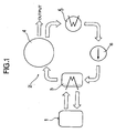
- a conventionally known waste heat recovering device for an internal combustion engine utilizing a Rankin cycle which includes an evaporator for generating vapor having a raised temperature and a raised pressure, namely, raised-temperature/pressure vapor using an exhaust gas from the internal combustion engine as a heat source, an expander for expanding the raised-temperature/pressure vapor to generate an output, a condenser for liquefying vapor having a dropped temperature and a dropped pressure, namely, dropped-temperature/pressure vapor discharged from the expander after the expansion, and a supply pump for supplying a liquid, e.g., water from the condenser to the evaporator.
- a liquid e.g., water from the condenser to the evaporator.
- the waste heat recovery efficiency can be increased by introducing the exhaust gas to the evaporator, while being maintained at a high temperature as much as possible, but the following problem is encountered in the conventional exhaust port structure: substantially the entire outer peripheral surface of the exhaust port liner is in contact with the cylinder head body and for this reason, the heat of the exhaust gas is propagated via the exhaust port liner to the cylinder head body and as a result , the temperature of the exhaust gas is dropped.
- an exhaust port structure for an internal combustion engine wherein a cylinder head has a cylinder head body and a cylindrical exhaust port liner, the cylindrical exhaust port liner being partially supported at a plurality of points on the cylinder head body, and a heat-insulating layer exists around the exhaust port liner.
- Sites existing respectively adjacent an inlet and an outlet for the exhaust gas and/or a valve stem-insertion section are selected as a plurality of partially supporting points on the exhaust port liner. By selecting such supporting points, an accuracy of attachment of the exhaust port liner to the cylinder head body can be ensured.
- a means for cooling the valve stem-insertion section is provided in the cylinder head body in order to maintain the positional accuracy of the valve stem-insertion section and inhibit the thermal expansion of the valve stem-insertion section to smoothly conduct the opening and closing movements of an exhaust valve.
- a waste heat recovering device 2 for an internal combustion engine 1 utilizing a Rankin cycle includes an evaporator 3 for generating a vapor having a raised temperature and a raised pressure, namely, a raised-temperature/pressure vapor, utilizing an exhaust gas from the internal combustion engine as a heat source, an expander 4 for expanding the raised-temperature/pres sure vapor to generate an output , a condenser 5 for liquefying a vapor having a dropped temperature and a dropped pressure, namely, dropped-temperature/pressure vapor discharged from the expander 4 after the expansion, and a supply pump 6 for supplying a liquid, e.g., water from the condenser 5 to the evaporator 3.
- a liquid e.g., water
- the evaporator 3 is connected to an exhaust port 8 in a cylinder head 7 in the internal combustion engine 1, and the cylinder head 7 has an exhaust port structure as described below in order to introduce a high-temperature exhaust gas into the evaporator 3.
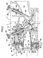
- the cylinder head 7 includes a cylinder head body 9 made of an aluminum alloy, and a cylindrical exhaust port liner 10 made of a stainless steel.
- the cylinder head body 9 has a relatively large cavity 12 extending from above a combustion chamber 11 toward the evaporator 3, and the exhaust port liner 10 is partially supported at a plurality of points on the cylinder head body 9 within the cavity 12.
- a heat-insulating layer 13 is provided around the exhaust port liner 10 by air existing in the cavity 12.
- two stays 16 made of a stainless steel are disposed in an opposed relation to each other at the site A existing at a portion of the outer peripheral surface adjacent the exhaust gas inlet, so that they sandwiches the valve stem-insertion section 15 and are substantially parallel to an axis a of a valve stem.
- Each of the stays 16 is welded at one end thereof to the site A.
- Three stays 17 made of a stainless steel are disposed at distances of 120 degree in a circumferential direction at the site B existing at the portion of the outer peripheral surface adjacent the exhaust gas outlet and are each welded at one end thereof to the site B.
- the other ends of the stays 16 and 17 have been formed by casting in the cylinder head body 9 in the course of forming the cylinder head body 9 in a casting process, as shown in Figs.2 and 5.
- Through-bores 18 and 19 are defined in the other ends of the stays 16 and 17 in order to enhance the effect of anchoring the stays 16 and 17.
- the two stays 16 existing at the portion of the outer peripheral surface adjacent the exhaust gas inlet are formed into a U-shape in section to have a rigidity.
- the expansion and shrinkage of the portion of the exhaust port liner 10 adjacent the exhaust gas inlet due to a heat is inhibited as much as possible to maintain the smooth opening and closing movements of the exhaust valve 14.
- the three stays 17 existing at the portion of the outer peripheral surface adjacent the exhaust gas outlet are formed from a thin stainless steel having a thickness of 0.5 mm, for example, so that they are resiliently deformable.
- the stays 17 have a function of permitting the expansion and shrinkage of the portion of the exhaust port liner 10 adjacent the exhaust gas outlet due to a heat.
- an inlet-defining portion 20 of the exhaust port liner 10 is loosely inserted into a bore 22 adjacent a valve seat 21, and an annular space between the valve seat 21 and a flange 23 of the exhaust port liner 10 existing in the vicinity of the inlet-defining portion 20 is filled with a heat-insulating annular seal member 24 having a cushioning property.
- a heat-insulating annular seal member 24 having a cushioning property.
- the valve stem-insertion section 15 includes a cylindrical portion 26 and a bottom wall portion 27 located adjacent the valve seat 21, and a valve stem-insertion bore 28 is defined in the bottom wall portion 27.
- the cylinder head body 9 has a holder tube 29 provided with its opposite ends opened so as to be opposed to an opening of the cylindrical portion 26, and a hollow valve stem guide 30 is retained on the holder tube 29 in the following manner: A slip-off preventing flange 31 provided on the valve stem guide 30 at a location adjacent the exhaust port liner 10 is engaged with an inner edge of one of openings 32 in the holder tube 30, and a cylindrical portion 33 located outside the slip-off preventing flange 31 is water-tightly fitted in the opening 32.
- a protrusion 34 located outside the cylindrical portion 33 is loosely inserted into the cylindrical portion 26 of the valve stem-insertion section 15.
- a valve stem 35 of the exhaust valve 14 extends through the insertion bore 28 in the bottom wall portion 27 and the valve stem guide 30.
- a cylindrical space defined by the cylindrical portion 26, the bottom wall portion 27, the protrusion 34 and the stem 35 is filled with a heat-insulating cylindrical seal member 36 having a cushioning property similar to that described above.
- a portion of the cylindrical seal member 36 protrudes from the cylindrical portion 26 to about against an end face of the cylindrical portion 33 of the valve stem guide 30.
- the valve stem guide 30 has a spring retainer-retaining bottomed cylindrical portion 38 of a cup shape provided at its intermediate portion, so that an outer peripheral surface of the bottomed cylindrical portion 38 is water-tightly fitted into the other opening 39 in the holder tube 29, with an outer peripheral edge of its bottom wall being engaged with a step 40 on the inner peripheral surface of the holder tube 29.
- a cooling water chamber 41 as a means for cooling the valve stem-insertion section 15 is defined within the holder tube 29 by the slip-off preventing flange 31 and the bottomed cylindrical portion 38.
- a heat-radiating flange 42 is provided at a portion of the valve stem guide 30, which is located within the cooling water chamber 41.
- the cavity 12 in the cylinder head body 9 opens into an end face of the cylinder head body 9 on the side of the evaporator 3, and an outlet-defining portion 44 of the exhaust port liner 10 protrudes from an opening 43 of the cavity 12.
- the exhaust port liner 10 is fitted into a bore 46 in an annular heat-insulating plate 45, and an outer periphery of the annular heat-insulating plate 45 is fitted into an annular recess 47 in the opening 43.
- a housing 48 of the evaporator 3 is provided at its end with a connecting tube 51 having a flange 50 and an opening 49 surrounding the outlet-defining portion 44, so that the evaporator 3 is mounted to the cylinder head 7 by fastening the flange 50 to the cylinder head body 9 by a plurality of bolts 52.
- An annular heat-insulating plate 54 is fitted into an annular recess 53 in the opening 49 and pushed by the annular heat-insulating plate 45 of the cylinder head 7.
- An exhaust gas-introducing pipe 55 of the evaporator 3 has a connecting tube 56 at its end.
- the connecting tube 56 is supported on a connecting tube 51 for the housing 48 through a plurality of stays 57 provided on an outer peripheral surface of the connecting tube 56.
- the connecting tube 56 has a smaller-diameter portion 58 fitted over an outer peripheral surface of an outer end of the outlet-defining portion 44 of the exhaust port liner 44, and a larger-diameter portion 59 leading to an outer end of the smaller-diameter portion 58 and fitted into a bore 60 in the annular heat-insulating plate 54.
- a clearance b is provided between an end face of the outlet-defining portion 44 and an annular projection 61 on an inner peripheral surface of the smaller-diameter portion 58 to permit the expansion and shrinkage of a portion of the exhaust port liner 10 adjacent the exhaust gas outlet due to the heat.
- An annular space between an inner peripheral surface of the larger-diameter portion 59 and the outer peripheral surface of the outlet-defining portion 44 is filled with a heat-insulating annular seal member 62 having a cushioning property similar to that described above .
- a heat-insulating annular seal member 62 having a cushioning property similar to that described above .
- 63 denotes an intake valve; 64 an intake port ; 65 and 66 valve springs; and 67 and 68 spring retainers.
- the heat-propagation path between the exhaust port liner 10 and the cylinder head body 9 can be reduced remarkably, whereby the exhaust gas can be maintained at a high temperature and introduced into the evaporator 3.
- the sites A and B existing adjacent the exhaust gas inlet and outlet and the valve stem-insertion section 15 are selected as the partially supporting points on the exhaust port liner 10 and hence, it is possible to ensure an accuracy of attachment of the exhaust port liner 10 to the cylinder head body 9.
- the cooling water chamber 4 is provided in the cylinder head body 9, whereby the valve stem-insertion section 15 of the exhaust port liner 10 can be cooled through the valve stem guide 30. Therefore, it is possible to maintain a positional accuracy of the valve stem-insertion section 15 and to inhibit the thermal expansion of the valve stem-insertion section 15 to smoothly conduct the opening and closing movements of the exhaust valve 14.
- a heat-insulating layer 69 formed by filling a heat-insulating powder material comprising nm-sized particles into the cavity 12 is used, as shown in Fig. 6.
- the term "filling" used herein means a filling of such an extent that a weak consolidating force is provided by applying a pressing force of about 0.06 MPa to the heat-insulating powder material placed into the cavity 12.
- the heat-insulating powder material used is a powder mixture comprising 66 % by weight of an SiO 2 powder having an average particle size of 7 nm (made under a trade name of Fumed silica by Nippon Aerogel, Co.) and 34 % by weight of a TiO 2 powder having an average particle size of 15 nm (made under a trade name of MT-150W by Teika, Co.).
- heat-insulating layer 69 If such heat-insulating layer 69 is used, because the forming particles are extremely fine, the following heat-insulating functions are provided: (a ) a thermal resistance in an area of contact of the adjacent particles is large; (b) a heat movement path through a large number of particles is complicated; and (c) a gap between the adjacent particles is very small and hence, a convection of air is hard to occur, and in addition, a heat-insulating function, such that TiO 2 exhibits an effect of scattering the radiant heat, is provided. Therefore, the heat-insulating layer 69 exhibits an excellent heat-insulating effect at a high temperature.
- the heat transfer coefficient of the heat-insulating layer 13 formed by air is increased steeply at a temperature equal to or higher than 750°C and is equal to or higher than 1 W/(m•K) at a temperature equal to or higher than 1000°C, but the heat transfer coefficient of the heat-insulating layer 69 formed of the heat-insulating powder material is maintained at about 0.1 W/(m ⁇ K) at a temperature equal to or higher than 1000°C.
- a protective layer may be formed on the inner peripheral surface of the exhaust port liner 10.
Landscapes
- Engineering & Computer Science (AREA)
- Mechanical Engineering (AREA)
- General Engineering & Computer Science (AREA)
- Chemical & Material Sciences (AREA)
- Combustion & Propulsion (AREA)
- Physics & Mathematics (AREA)
- Acoustics & Sound (AREA)
- Geometry (AREA)
- Cylinder Crankcases Of Internal Combustion Engines (AREA)
- Exhaust Silencers (AREA)
Abstract
Description
Claims (3)
- An exhaust port structure for an internal combustion engine, wherein a cylinder head (7) has a cylinder head body (9) and a cylindrical exhaust port liner (10), said exhaust port liner (10) being partially supported at a plurality of points on said cylinder head body (9), and a heat -insulating layer (13, 69) exists around said exhaust port liner (10).
- An exhaust port structure for an internal combustion engine according to claim 1, wherein a plurality of partially supporting points on said exhaust port liner (10) include a site (A) existing adjacent an exhaust gas inlet and a site (B) existing adjacent an exhaust gas outlet.
- An exhaust port structure for an internal combustion engine according to claim 2, wherein the partially supporting points on said exhaust port liner (10) include a valve stem-insertion section (15), and a means (41) for cooling said valve stem-insertion section (15) is provided in said cylinder head body (9).
Applications Claiming Priority (3)
| Application Number | Priority Date | Filing Date | Title |
|---|---|---|---|
| JP31348499 | 1999-11-04 | ||
| JP31348499A JP2001132444A (en) | 1999-11-04 | 1999-11-04 | Exhaust port structure of internal combustion engine |
| PCT/JP2000/007740 WO2001033066A1 (en) | 1999-11-04 | 2000-11-02 | Exhaust port structure of internal combustion engine |
Publications (2)
| Publication Number | Publication Date |
|---|---|
| EP1231373A1 true EP1231373A1 (en) | 2002-08-14 |
| EP1231373A4 EP1231373A4 (en) | 2005-04-06 |
Family
ID=18041873
Family Applications (1)
| Application Number | Title | Priority Date | Filing Date |
|---|---|---|---|
| EP00971759A Withdrawn EP1231373A4 (en) | 1999-11-04 | 2000-11-02 | Exhaust port structure of internal combustion engine |
Country Status (4)
| Country | Link |
|---|---|
| US (1) | US6629516B1 (en) |
| EP (1) | EP1231373A4 (en) |
| JP (1) | JP2001132444A (en) |
| WO (1) | WO2001033066A1 (en) |
Cited By (5)
| Publication number | Priority date | Publication date | Assignee | Title |
|---|---|---|---|---|
| FR2851785A1 (en) * | 2003-02-28 | 2004-09-03 | Renault Sa | HIGH CONSERVATION OF THERMAL ENERGY EXHAUST |
| DE102008002514A1 (en) * | 2008-06-18 | 2009-12-24 | Federal-Mogul Nürnberg GmbH | Piston, cylinder liner or other, the combustion chamber of an internal combustion engine limiting engine component and method for producing the same |
| WO2011160624A1 (en) * | 2010-06-24 | 2011-12-29 | Man Diesel & Turbo Se | Cylinder head and internal combustion engine equipped therewith |
| WO2013045018A3 (en) * | 2011-10-01 | 2014-01-23 | Volkswagen Aktiengesellschaft | Cylinder head having an integrated exhaust manifold for an internal combustion engine and method for producing a cast component, in particular a cylinder head for an internal combustion engine |
| WO2021205463A1 (en) * | 2020-04-10 | 2021-10-14 | Tvs Motor Company Limited | An internal combustion engine and a sleeve member thereof |
Families Citing this family (8)
| Publication number | Priority date | Publication date | Assignee | Title |
|---|---|---|---|---|
| JP4191353B2 (en) * | 2000-01-26 | 2008-12-03 | 本田技研工業株式会社 | Internal combustion engine |
| DE10117513A1 (en) * | 2001-04-07 | 2002-10-17 | Volkswagen Ag | Internal combustion engine with direct injection |
| JP3881872B2 (en) | 2001-11-15 | 2007-02-14 | 本田技研工業株式会社 | Internal combustion engine |
| US7305763B2 (en) * | 2005-07-26 | 2007-12-11 | Board Of Trustees Of Michigan State University | Hydroformed port liner |
| US20070137604A1 (en) * | 2005-12-21 | 2007-06-21 | Silseth John R | Motorcycle engine |
| US7966986B2 (en) * | 2007-04-13 | 2011-06-28 | Hyspan Precision Products, Inc. | Cylinder head |
| DE102007030482B4 (en) * | 2007-06-30 | 2018-12-20 | Dr. Ing. H.C. F. Porsche Aktiengesellschaft | Cooling channels in the cylinder head of an internal combustion engine |
| DE102014100568A1 (en) * | 2014-01-20 | 2015-07-23 | Tenedora Nemak, S.A. De C.V. | Casting and insert for such a casting |
Family Cites Families (10)
| Publication number | Priority date | Publication date | Assignee | Title |
|---|---|---|---|---|
| CA1056246A (en) * | 1975-04-22 | 1979-06-12 | Shuichi Yamazaki | Exhaust port liner system in engines |
| DE2616027A1 (en) * | 1975-04-22 | 1976-11-04 | Honda Motor Co Ltd | COMBUSTION ENGINE WITH EXHAUST INNER PIPE |
| JPS5257420A (en) * | 1975-11-07 | 1977-05-11 | Honda Motor Co Ltd | Exhaust port liner equipment for engine |
| JPS5273210A (en) | 1975-12-17 | 1977-06-18 | Honda Motor Co Ltd | Exhaust port liner for internal conbustion engine combustion engine |
| US4430856A (en) * | 1981-11-13 | 1984-02-14 | Deere & Company | Port liner and method of assembly |
| DE3615018C1 (en) * | 1986-05-02 | 1987-05-21 | Mtu Friedrichshafen Gmbh | Valve stem guide for an exhaust valve |
| JPS6345046A (en) | 1986-08-12 | 1988-02-26 | 日立化成工業株式会社 | Manufacture of insulating substrate containing metallic core |
| JPH0730928Y2 (en) * | 1986-09-10 | 1995-07-19 | 日野自動車工業株式会社 | Engine cylinder head |
| JPH05256191A (en) | 1992-03-13 | 1993-10-05 | Nissan Motor Co Ltd | Exhaust passage of combustion device |
| JP2530795B2 (en) * | 1992-03-27 | 1996-09-04 | 本田技研工業株式会社 | cylinder head |
-
1999
- 1999-11-04 JP JP31348499A patent/JP2001132444A/en not_active Withdrawn
-
2000
- 2000-11-02 EP EP00971759A patent/EP1231373A4/en not_active Withdrawn
- 2000-11-02 WO PCT/JP2000/007740 patent/WO2001033066A1/en not_active Ceased
- 2000-11-02 US US10/111,395 patent/US6629516B1/en not_active Expired - Fee Related
Cited By (7)
| Publication number | Priority date | Publication date | Assignee | Title |
|---|---|---|---|---|
| FR2851785A1 (en) * | 2003-02-28 | 2004-09-03 | Renault Sa | HIGH CONSERVATION OF THERMAL ENERGY EXHAUST |
| EP1455075A1 (en) * | 2003-02-28 | 2004-09-08 | Renault s.a.s. | Exhaust channel with high thermal energie conservation |
| DE102008002514A1 (en) * | 2008-06-18 | 2009-12-24 | Federal-Mogul Nürnberg GmbH | Piston, cylinder liner or other, the combustion chamber of an internal combustion engine limiting engine component and method for producing the same |
| WO2011160624A1 (en) * | 2010-06-24 | 2011-12-29 | Man Diesel & Turbo Se | Cylinder head and internal combustion engine equipped therewith |
| WO2013045018A3 (en) * | 2011-10-01 | 2014-01-23 | Volkswagen Aktiengesellschaft | Cylinder head having an integrated exhaust manifold for an internal combustion engine and method for producing a cast component, in particular a cylinder head for an internal combustion engine |
| EP2761157A2 (en) * | 2011-10-01 | 2014-08-06 | Volkswagen Aktiengesellschaft | Cylinder head having an integrated exhaust manifold for an internal combustion engine and method for producing a cast component, in particular a cylinder head for an internal combustion engine |
| WO2021205463A1 (en) * | 2020-04-10 | 2021-10-14 | Tvs Motor Company Limited | An internal combustion engine and a sleeve member thereof |
Also Published As
| Publication number | Publication date |
|---|---|
| WO2001033066A1 (en) | 2001-05-10 |
| JP2001132444A (en) | 2001-05-15 |
| EP1231373A4 (en) | 2005-04-06 |
| US6629516B1 (en) | 2003-10-07 |
Similar Documents
| Publication | Publication Date | Title |
|---|---|---|
| US6629516B1 (en) | Exhaust port structure of internal combustion engine | |
| KR101753793B1 (en) | Sleeve valve assembly with cooling path | |
| EP2082119B1 (en) | Valve seat insert for a piston engine | |
| US7128029B2 (en) | Water-cooled cylinder head for a multicylinder internal-combustion engine | |
| US5954038A (en) | Combustion face insert | |
| EP1251260A1 (en) | Internal combustion engine | |
| US10390971B2 (en) | Cylinder head, element and flange of a piston engine | |
| EP1239138B1 (en) | Waste heat recovery device of internal combustion engine | |
| NZ533393A (en) | Piston for an internal combustion engine | |
| US6874479B2 (en) | Internal combustion engine | |
| JP2000161130A (en) | Head overheat part cooling structure for monoblock engine | |
| JP3555431B2 (en) | Structure of heat shield type engine | |
| JPH0730928Y2 (en) | Engine cylinder head | |
| JP2002115601A (en) | Exhaust port structure for internal combustion engine | |
| JPH0332762Y2 (en) | ||
| JP4090109B2 (en) | Intake manifold for internal combustion engine | |
| Kawamura | Thermos Construction Made of Si3N4 in the Heat Insulated Engine | |
| GB1603130A (en) | Heat pipe for the reduction of the temperature in thermally stressed regions of machines | |
| JPH0426785A (en) | Formation of sacrificial film on cooling water passage in aluminum cylinder head | |
| JPS6166846A (en) | Cylinder head for ceramics insulating engine | |
| JPH0517145U (en) | Adiabatic piston | |
| JPH06336950A (en) | Heat shield engine | |
| JPH0230438B2 (en) | ENJINREIKYAKUSUINONETSUKOKANKI | |
| HU193484B (en) | Aluminium cylinder of cast-iron liner expediently for two-stroke internal combustion engines |
Legal Events
| Date | Code | Title | Description |
|---|---|---|---|
| PUAI | Public reference made under article 153(3) epc to a published international application that has entered the european phase |
Free format text: ORIGINAL CODE: 0009012 |
|
| 17P | Request for examination filed |
Effective date: 20020523 |
|
| AK | Designated contracting states |
Kind code of ref document: A1 Designated state(s): AT BE CH CY DE DK ES FI FR GB GR IE IT LI LU MC NL PT SE TR |
|
| AX | Request for extension of the european patent |
Free format text: AL;LT;LV;MK;RO;SI |
|
| RBV | Designated contracting states (corrected) |
Designated state(s): AT BE CH CY DE ES FR GB IT LI |
|
| A4 | Supplementary search report drawn up and despatched |
Effective date: 20050223 |
|
| RIC1 | Information provided on ipc code assigned before grant |
Ipc: 7F 02F 1/42 A Ipc: 7F 02B 77/11 B Ipc: 7F 01L 3/08 B |
|
| 17Q | First examination report despatched |
Effective date: 20060718 |
|
| STAA | Information on the status of an ep patent application or granted ep patent |
Free format text: STATUS: THE APPLICATION IS DEEMED TO BE WITHDRAWN |
|
| 18D | Application deemed to be withdrawn |
Effective date: 20061129 |