EP1231011A2 - Bonding structure of valve seat and method of making the same - Google Patents
Bonding structure of valve seat and method of making the same Download PDFInfo
- Publication number
- EP1231011A2 EP1231011A2 EP02002768A EP02002768A EP1231011A2 EP 1231011 A2 EP1231011 A2 EP 1231011A2 EP 02002768 A EP02002768 A EP 02002768A EP 02002768 A EP02002768 A EP 02002768A EP 1231011 A2 EP1231011 A2 EP 1231011A2
- Authority
- EP
- European Patent Office
- Prior art keywords
- valve seat
- seat insert
- head
- cylinder head
- reduced diameter
- Prior art date
- Legal status (The legal status is an assumption and is not a legal conclusion. Google has not performed a legal analysis and makes no representation as to the accuracy of the status listed.)
- Granted
Links
Images


Classifications
-
- F—MECHANICAL ENGINEERING; LIGHTING; HEATING; WEAPONS; BLASTING
- F01—MACHINES OR ENGINES IN GENERAL; ENGINE PLANTS IN GENERAL; STEAM ENGINES
- F01L—CYCLICALLY OPERATING VALVES FOR MACHINES OR ENGINES
- F01L3/00—Lift-valve, i.e. cut-off apparatus with closure members having at least a component of their opening and closing motion perpendicular to the closing faces; Parts or accessories thereof
- F01L3/02—Selecting particular materials for valve-members or valve-seats; Valve-members or valve-seats composed of two or more materials
-
- B—PERFORMING OPERATIONS; TRANSPORTING
- B23—MACHINE TOOLS; METAL-WORKING NOT OTHERWISE PROVIDED FOR
- B23K—SOLDERING OR UNSOLDERING; WELDING; CLADDING OR PLATING BY SOLDERING OR WELDING; CUTTING BY APPLYING HEAT LOCALLY, e.g. FLAME CUTTING; WORKING BY LASER BEAM
- B23K20/00—Non-electric welding by applying impact or other pressure, with or without the application of heat, e.g. cladding or plating
- B23K20/12—Non-electric welding by applying impact or other pressure, with or without the application of heat, e.g. cladding or plating the heat being generated by friction; Friction welding
- B23K20/129—Non-electric welding by applying impact or other pressure, with or without the application of heat, e.g. cladding or plating the heat being generated by friction; Friction welding specially adapted for particular articles or work
-
- B—PERFORMING OPERATIONS; TRANSPORTING
- B23—MACHINE TOOLS; METAL-WORKING NOT OTHERWISE PROVIDED FOR
- B23K—SOLDERING OR UNSOLDERING; WELDING; CLADDING OR PLATING BY SOLDERING OR WELDING; CUTTING BY APPLYING HEAT LOCALLY, e.g. FLAME CUTTING; WORKING BY LASER BEAM
- B23K20/00—Non-electric welding by applying impact or other pressure, with or without the application of heat, e.g. cladding or plating
- B23K20/12—Non-electric welding by applying impact or other pressure, with or without the application of heat, e.g. cladding or plating the heat being generated by friction; Friction welding
- B23K20/129—Non-electric welding by applying impact or other pressure, with or without the application of heat, e.g. cladding or plating the heat being generated by friction; Friction welding specially adapted for particular articles or work
- B23K20/1295—Welding studs
-
- F—MECHANICAL ENGINEERING; LIGHTING; HEATING; WEAPONS; BLASTING
- F01—MACHINES OR ENGINES IN GENERAL; ENGINE PLANTS IN GENERAL; STEAM ENGINES
- F01L—CYCLICALLY OPERATING VALVES FOR MACHINES OR ENGINES
- F01L3/00—Lift-valve, i.e. cut-off apparatus with closure members having at least a component of their opening and closing motion perpendicular to the closing faces; Parts or accessories thereof
- F01L3/22—Valve-seats not provided for in preceding subgroups of this group; Fixing of valve-seats
-
- Y—GENERAL TAGGING OF NEW TECHNOLOGICAL DEVELOPMENTS; GENERAL TAGGING OF CROSS-SECTIONAL TECHNOLOGIES SPANNING OVER SEVERAL SECTIONS OF THE IPC; TECHNICAL SUBJECTS COVERED BY FORMER USPC CROSS-REFERENCE ART COLLECTIONS [XRACs] AND DIGESTS
- Y10—TECHNICAL SUBJECTS COVERED BY FORMER USPC
- Y10T—TECHNICAL SUBJECTS COVERED BY FORMER US CLASSIFICATION
- Y10T29/00—Metal working
- Y10T29/49—Method of mechanical manufacture
- Y10T29/49229—Prime mover or fluid pump making
- Y10T29/49298—Poppet or I.C. engine valve or valve seat making
- Y10T29/49306—Valve seat making
Definitions
- the present invention relates to a bonding structure of a valve seat and more particularly to structure and method for bonding the valve seat insert to a head by pressure welding such that the head physically secures the valve seat insert for forming the valve seat for an internal combustion engine.
- annular valve seat insert is made of a sintered ferroalloy, and the intake and exhaust port openings of a cylinder head are made of an aluminum alloy.
- the valve seat insert is bonded to the cylinder head by heating and pressing the valve seat insert into a recess formed at each port opening.
- the annular valve seat insert is required to be relatively thick to counter internal stress generated due to shrink. Therefore, bonding the valve seat insert by welding or others, which generates less internal stress, has been tried such that the valve seat insert becomes relatively thin.
- Japanese Unexamined Patent Publication No. 11-50823 discloses that the valve seat insert is bonded by friction welding, which applies an ultrasonic vibration.
- Japanese Unexamined Patent Publication No. 8-296417 and No. 2000-263241 disclose that the valve seat insert is bonded by electric resistance welding.
- the valve seat insert itself may contain a diffusible material, which is diffusible to an aluminum alloy, or may includes a layer of the diffusible material, or solder may be interposed between the cylinder head and the valve seat insert.
- the present invention addresses the above-mentioned problems traceable to the bonding strength between a head and a valve seat insert by improving a bonding structure such that the head physically secures the valve seat insert.
- a bonding structure of a valve seat has a port opening of a metallic head and an annular metallic valve seat insert.
- the valve seat insert includes an outer reduced diameter surface on its outer circumference.
- the material of the valve seat insert is harder than that of the head.
- the head plastically deforms upon pressing the valve seat insert toward the head. The deformed head occupies any gap around the outer reduced diameter surface.
- the present invention also provides a method of making a valve seat.
- the method includes pressing a valve seat insert, which provides an outer reduced diameter surface, toward a head, rotating the valve seat insert while pressing the valve seat insert, and cooling the valve seat insert and the head.
- a bonding structure 1 of a valve seat is constituted of a cylinder head 5 and an a valve seat insert 6.
- a recess 12 is formed at the end of the port opening 11 of the cylinder head 5 by pressing the valve seat insert 6 toward the cylinder head 5.
- the valve seat insert 6, which is annular in shape, is bonded to the cylinder head 5 so as to be fitted into the recess 12.
- An inclined surface 23 as an outer reduced diameter surface, which gradually reduces its diameter toward the opposite side of the cylinder head 5, resides on an outer circumference of the valve seat insert 6.
- valve seat insert 6 facing a combustion chamber, or the opposite side of the cylinder head 5, is machined to a tapered surface with an angle of 45 degrees relative to the central axis of the port opening 11, thus forming a valve seat 15.
- the valve body 7 is disposed on the valve seat 15 so as to move up and down relative to the valve seat 15 of the valve seat insert 6.
- Fig. 2 shows a valve seat insert and a cylinder head before bonding.
- the cylinder head 5 is made of a metal such as an aluminum alloy, for example, Al-Si.
- the valve seat insert 6 is made of a metal such as a ferroalloy or a sinter of those alloys.
- the material of the valve seat insert 6 is harder than that of the cylinder head 5.
- the recess 21 of the cylinder head 5 is constituted of a first recess 211, the diameter D2 of which is larger than the diameter D1 of the port opening 11, a second recess 212, the diameter D3 of which is much larger than the diameter D2 of the first recess 211, and a step 213 between the first recess 211 and the second recess 212.
- the valve seat insert 6 is annular in shape, and has an inside diameter of D5, an outermost outside diameter of D7 and a thickness of H5.
- the valve seat insert 6 provides a truncated cone-shaped first inclined surface 23, or an outer reduced diameter surface, which is positioned farther from the cylinder head 5 than an outermost point 22 of the valve seat insert 6.
- the valve seat insert 6 also provides a truncated cone-shaped second inclined surface 24, which is positioned closer to the cylinder head 5 than the outermost point 22. Since the deformed metal shaped into a wedge occupies the gap around the first inclined surface 23, the angle ⁇ of the first inclined surface 23 is preferably 10 to 15 degrees. Also, since the second inclined surface 24 forces the deformed metal out to the first inclined surface 23, the angle ⁇ of the second inclined surface 24 is preferably 45 degrees or below.
- the outermost outside diameter D7 of the vale seat insert 6 is preferably a little smaller than the diameter D3 of the second recess 212 so that the deformed metal smoothly flows onto the first inclined surface 23.
- the bottom diameter D6 of an end surface facing the cylinder head 5 is preferably a little smaller than the diameter D2 of the first recess 211 so that the second inclined surface 24 abuts against the edge of the step 213.
- the diameter D5 of the valve seat insert 6 is preferably a little smaller than the diameter D1 of the port opening 11 so as to guide a burr of the deformed metal.
- the thickness H5 of the valve seat insert 6 is preferably a little larger than the depth H1 of the recess 21 so as to save a leave for upsetting upon pressing.
- Fig. 3 shows a procedure for bonding a valve seat insert 6 and a cylinder head 5.
- the valve seat insert 6 is pressed toward the cylinder head 5 with its rotated.
- the valve seat insert 6 is fitted into the recess 21 of the cylinder head 5.
- the edge of the step 213 abuts against the second inclined surface 24.
- the valve seat insert 6 is pressed against the cylinder head 5 by applying predetermined pressure P to the valve seat insert 6.
- Fig. 3b as the valve seat insert 6 is pressed with its rotated, the edge of the step 213 is deformed, and flows along the second inclined surface 24.
- the deformed metal forced out to the outermost point 22 crosses the outermost point 22, and flows along the first inclined surface 23 toward the opposite side of the cylinder head 5.
- the end of the valve seat insert 6 facing the cylinder head 5 abuts against the bottom of the first recess 211 of the cylinder head 5, and continues to be pressed against the cylinder head 5 with its rotated until the deformed metal occupies any gap around the first recess 211.
- the valve seat insert 6 is stopped rotating, and is upset by pressing. As the cylinder head 5 abutting against the valve seat insert 6 is deformed, the valve seat insert 6 is further pushed in. The deformed metal is forced out onto the first inclined surface 23 and to the port opening 11.
- the wedge-shaped deformed metal 14 around the first inclined surface 23 of the valve seat insert 6 is solidified.
- the solidified deformed metal 14 occupies any gap around the valve seat insert 6, and physically secures the valve seat insert 6 to the cylinder head 5.
- the bonding structure 1 of the valve seat with designed dimensions is made by the following steps: removing a burr of the deformed metal 14 by machining the inner surface of the valve seat insert 6 and the distal end of the valve seat insert relative to the cylinder head 5; and forming the valve seat 15 by machining the edge between the distal end and the inner surface.
- valve seat 15 firmly secured is selected based on its appearance test.
- a cylinder head 5A provides a recess 31, which is D13 in diameter and H11 in depth, and the diameter D13 is larger than the diameter D11 of the port opening 11.
- a valve seat insert 6A is annular in shape, and is D15 in inside diameter, D17 in outermost outside diameter and H15 in thickness.
- the valve seat insert 6A also provides a truncated cone-shaped inclined surface 33 or an outer reduced diameter surface on its outer circumference, the angle of the inclined surface 33 is ⁇ degree perpendicular to the central axis of the port opening 11,.
- the inclined surface 33 is positioned farther from the cylinder head 5A than an outermost point 32 of the valve seat insert 6A.
- the outermost outside diameter D17 of the vale seat insert 6A is preferably a little smaller than the diameter D13 of the recess 31 so that the deformed metal smoothly flows onto the inclined surface 33.
- the diameter D15 of the valve seat insert 6A is preferably a little smaller than the diameter D11 of the port opening 11 so as to guide a burr of the deformed metal.
- the thickness H15 of the valve seat insert 6A is preferably a little larger than the depth H11 of the recess 31 so as to save a leave for upsetting upon pressing.
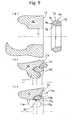
- Fig. 5 shows a procedure for bonding a valve seat insert 6A to a cylinder head 5A.
- the valve seat insert 6A is pressed toward the cylinder head 5A with its rotated.
- the valve seat insert 6A is fitted into the recess 31 of the cylinder head 5A.
- the end of the valve seat insert 6A abuts against the bottom of the recess 31.
- the valve seat insert 6A is pressed against the cylinder head 5A by applying predetermined pressure P to the valve seat insert 6A.
- Fig. 5b as the valve seat insert 6A is pressed with its rotated, the bottom of the recess 31 is deformed, and the deformed metal crosses the outermost point 22, then flows along the inclined surface 33.
- the valve seat insert 6A is stopped rotating, and continues to be pressed. Since the bottom of the cylinder head 5A abutting against the valve seat insert 6A is deformed, the valve seat insert 6A is further pushed in. The deformed metal is forced out onto the inclined surface 33, and is shaped into a wedge. As shown in Fig. 5d, the wedge-shaped deformed metal 34 is solidified by cooling, and is united with a base metal of the cylinder head 5A. The wedge-shaped deformed metal 34 occupies any gap around the valve seat insert 6A, and physically secures the valve seat insert 6A to the cylinder head 5A. As shown in Fig.
- the bonding structure 1A of the valve seat with designed dimensions is made by the following steps: removing a burr of the deformed metal 34 by machining the inner surface of the valve seat insert 6A and the distal end of the valve seat insert 6A relative to the cylinder head 5A; and forming the valve seat 35 by machining the edge between the distal end and the inner surface.
- the deformed metal 34 does not occupy the gap around the inclined surface 33 enough, the deformed metal 34 is defectively formed with some gaps after removing the burr. Therefore, the firmly secured valve seat 35 is selected based on its appearance test.
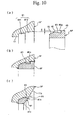
- a valve seat insert 6B provides an inclined surface 43 and an outer reduced diameter surface 42 on its outer circumference.
- the inclined surface 43 is positioned closer to the cylinder head 5B than an outermost surface 41 of the valve seat insert 6B, as well as that in the first embodiment.
- the outer reduced diameter surface 42 which is semicircular in shape, is positioned farther from the cylinder head 5B than the outermost surface 41.
- the valve seat insert 6B also provides a cylindrical surface 44, the diameter of which is smaller than the diameter of the outermost surface 41, on its outer circumference.
- the cylindrical surface 44 is positioned farther from the cylinder head 5B than the outer reduced diameter surface 42.
- a clearance ⁇ is set between the cylindrical surface 44 and the outermost surface 41.
- the deformed metal flows along the inclined surface 43, and crosses the outmost surface 41, then occupies any gap around the outer reduced diameter surface 42.
- the deformed metal occupying the gap around the outer reduced diameter surface 42 is solidified, and is united with a base metal of the cylinder head 5B. Also, since the deformed metal occupying the gap around the outer reduced diameter surface 42 is forced out through the clearance ⁇ , and is exposed outside. Therefore, the outer reduced diameter surface 42 filled with the deformed metal is checked based on its appearance.
- a valve seat insert 6C provides an inclined surface 53 and an outer reduced diameter surface 52 on its outer circumference.
- the inclined surface 53 is positioned closer to the cylinder head 5C than an outermost point 51 of the valve seat insert 6C, as well as that in the first embodiment.
- the outer reduced diameter surface 52 which is a catch, is positioned farther from the cylinder head 5C than the outermost point 51.
- the valve seat insert 6C also provides another peak point 54, the diameter of which is smaller than the diameter of the outermost point 51, on its outer circumference.
- the peak point 54 is positioned farther from the cylinder head 5C than the outer reduced diameter surface 52.
- a clearance ⁇ is set between the peak point 54 and the outermost point 51.
- the deformed metal flows along the inclined surface 53, and crosses the outmost point 51, then occupies any gap around the outer reduced diameter surface 52 as a catch.
- the deformed metal occupying the gap around the outer reduced diameter surface 52 is solidified, and is united with a base metal of the cylinder head 5C. Also, since the deformed metal occupying the gap around the outer reduced diameter surface 52 is forced out through the clearance ⁇ , the outer reduced diameter surface 52 filled with the deformed metal is checked based on its appearance.
- the shape of the cylinder head 5D is the same as that in the first embodiment except that the second recess is a truncated cone-shaped recess 60.
- a valve seat insert 6D provides a first inclined surface 61 and a second inclined surface 62 on its outer circumference.
- the first and second inclined surfaces 61, 62 which are truncated cone-shaped, are positioned on the outer circumference of the valve seat insert 6D.
- the valve seat insert 6D also provides an outer reduced diameter surface 63 as a catch, which is an annular groove.
- the outer reduced diameter surface 63 is positioned between the first and second inclined surfaces 61, 62, and provides a step for inhibiting the valve seat insert 6D from falling out.
- a clearance ⁇ is set between the first and second inclined surfaces 61, 62.
- the deformed metal flows along the inclined surface 61, and occupies any gap around the outer reduced diameter surface 63.
- the deformed metal occupying the gap around the outer reduced diameter surface 63 is solidified, and is united with a base metal of the cylinder head 5D. Also, since the deformed metal occupying the gap around the outer reduced diameter surface 63 is forced out through the clearance ⁇ , the outer reduced diameter surface 63 filled with the deformed metal is checked based on its appearance.
- a valve seat insert 6E provides a first inclined surface 73 as an outer reduced diameter surface and a second inclined surface 74 on its outer circumference.
- the first inclined surface 73 which is truncated cone-shaped, is positioned farther from the cylinder head 5E than an outermost point 72 of the valve seat insert 6E.
- the second inclined surface 74 which is truncated cone-shaped, is positioned closer to the cylinder head 5E than the outermost point 72.
- the valve seat insert 6E also provides a third inclined surface 75 on its inner circumference, and has an edge 76 on one end.
- a valve seat 77c is formed by the following steps: forming the port opening 11 by machining the inner surface 11a of the cylinder head 5E and the inner surface 77a of the valve seat insert 6E together; forming a plate-shaped end by machining the end 11b of the cylinder head 5E and the end 77b of the valve seat insert 77b together; and machining the edge between the inner surface 77a and the end 77b.
- the deformed metal occupies the gap around the first inclined surface 73 enough, and the first inclined surface 73 filled with the deformed metal is checked after machining based on its appearance.
- the cylinder head 5F provides a recess 81 at the end of the port opening 11, and the recess 81 is constituted of a first recess 811 and a second recess 812.
- a valve seat insert 6F provides a first inclined surface 83 as an outer reduced diameter surface and a second inclined surface 84, on its outer circumference.
- the first inclined surface 83 which is truncated cone-shaped, is positioned farther from the cylinder head 5F than a peak point 82 of the valve seat insert 6F.
- the second inclined surface 84 which is truncated cone-shaped, is positioned closer to the cylinder head 5F than the peak point 82.
- the valve seat insert 6F also provides a cap portion 85 and a step 85a.
- the cap portion 85 is positioned at the distal end of the valve seat insert 6F relative to the cylinder head 5F.
- the step 85a is positioned between the first inclined surface 83 and the cap portion 85.
- the diameter of the peak point 82 is substantially equal to the diameter of the second recess 812.
- the diameter of the cap portion 85 is larger than the diameter of the peak point 82,
- a clearance ⁇ is set between the cap portion 85 and the peak point 82.
- a valve seat 87c is formed by the following steps: forming a plate-shaped end by machining the end 11b of the cylinder head 5F and the end 87b of the valve seat insert 6F together; simultaneously removing a portion corresponding to the cap portion 85 of the valve seat insert 6F; and machining the edge between the inner surface of the valve seat insert 6F and the end 87b.
- the deformed metal occupies the gap around the first inclined surface 83 enough, and the first inclined surface 83 filled with the deformed metal is checked after machining based on its appearance.
- the cylinder head is deformed upon pressing the valve seat insert to the head, and the deformed metal occupies the gap around the outer reduced diameter surface of the valve seat insert, then the valve seat insert is physically secured to the head.
- the valve seat insert is firmly bonded, irrespective of a state of bonding between different metals.
- the valve seat insert may be thinner as compared with those made by heating and press-fitting, and design requirements about dimensions and materials of the valve seat insert may be improved.
- the deformed metal occupying the gap around the outer reduced diameter surface of the valve seat insert is checked based on its appearance. Thereby, quality control about a state of bonding is ensured.
- the deformed metal occupying the gap around the outer reduced diameter surface of the valve seat insert firmly secures the valve seat insert.
- the deformed metal easily occupies the gap around the outer reduced diameter surface of the valve seat insert, and the outer reduced diameter surface filled with the deformed metal is easily checked.
- the deformed metal occupies the gap around the outer reduced diameter surface of the valve seat insert enough.
- initial thrust force upon pressing is reduced.
- the metal deformed upon friction welding secures the valve seat insert to the head.
- design requirements about dimensions and materials of the valve seat insert may be improved, for example, thickness of the valve seat insert may become a relatively thin.
- a bonding structure of a valve seat has a port opening of a metallic head and an annular metallic valve seat insert.
- the valve seat insert includes an outer reduced diameter surface on its outer circumference.
- the material of the valve seat insert is harder than that of the head.
- the head plastically deforms upon pressing the valve seat insert toward the head. The deformed metal occupies any gap around the outer reduced diameter surface.
Landscapes
- Engineering & Computer Science (AREA)
- Mechanical Engineering (AREA)
- General Engineering & Computer Science (AREA)
- Cylinder Crankcases Of Internal Combustion Engines (AREA)
- Pressure Welding/Diffusion-Bonding (AREA)
- Lift Valve (AREA)
- Forging (AREA)
Abstract
Description
Claims (12)
- A bonding structure of a valve seat, comprising:wherein the material of the valve seat insert is harder than that of the head, the head plastically deforms upon pressing the valve seat insert toward the head, part of the deformed metal occupies any gap around the outer reduced diameter surface.a metallic head defining a port opening;an annular metallic valve seat insert providing an outer reduced diameter surface on its outer circumference;
- The bonding structure of the valve seat according to claim 1, wherein the deformed metal occupying the gap around the outer reduced diameter surface is exposed outside.
- The bonding structure of the valve seat according to claim 2, wherein the cross section of the deformed metal occupying the gap around the outer reduced diameter surface is wedge-shaped.
- The bonding structure of the valve seat according to claim 1, wherein the outer reduced diameter surface gradually reduces its diameter from an outermost point of the valve seat insert toward the opposite side of the head.
- The bonding structure of the valve seat according to claim 1, wherein an inclined surface resides on the outer circumference of the valve seat insert closer to the head.
- The bonding structure of the valve seat according to claim 5, wherein the end of the valve seat insert facing the head provides a sharp edge.
- The bonding structure of the valve seat according to claim 1, wherein the deformed metal is produced due to friction welding such that the valve seat insert is pressed toward the head with its rotated.
- The bonding structure of the valve seat according to claim 1, wherein the deformed metal is produced due to friction welding such that the valve seat insert is pressed toward the head with its vibrated by an ultrasonic vibrator.
- The bonding structure of the valve seat according to claim 1, wherein the head is a cylinder head of an internal combustion engine, and the valve seat insert forms a valve seat of the cylinder head.
- The bonding structure of the valve seat according to claim 1, wherein the valve seat insert contains a diffusible material and/or includes a layer of the diffusible material, such as copper, zinc, tin, magnesium and alloys of them.
- A method of making a valve seat, comprising the steps of:pressing a valve seat insert, which provides an outer reduced diameter surface, toward a head;rotating the valve seat insert while pressing the valve seat insert; andcooling the valve seat insert and the head.
- The method of bonding the valve seat insert to the head according to claim 11, further comprising the steps of:stopping the valve seat insert; andpressing the valve seat insert.
Applications Claiming Priority (2)
| Application Number | Priority Date | Filing Date | Title |
|---|---|---|---|
| JP2001031863 | 2001-02-08 | ||
| JP2001031863A JP4178758B2 (en) | 2001-02-08 | 2001-02-08 | Joint structure of valve seat |
Publications (3)
| Publication Number | Publication Date |
|---|---|
| EP1231011A2 true EP1231011A2 (en) | 2002-08-14 |
| EP1231011A3 EP1231011A3 (en) | 2004-03-10 |
| EP1231011B1 EP1231011B1 (en) | 2006-01-25 |
Family
ID=18895884
Family Applications (1)
| Application Number | Title | Priority Date | Filing Date |
|---|---|---|---|
| EP02002768A Expired - Lifetime EP1231011B1 (en) | 2001-02-08 | 2002-02-07 | Bonding structure of valve seat insert and method of making the same |
Country Status (4)
| Country | Link |
|---|---|
| US (1) | US6536397B2 (en) |
| EP (1) | EP1231011B1 (en) |
| JP (1) | JP4178758B2 (en) |
| DE (1) | DE60208827T2 (en) |
Cited By (6)
| Publication number | Priority date | Publication date | Assignee | Title |
|---|---|---|---|---|
| KR20050100722A (en) * | 2004-04-14 | 2005-10-20 | 현대자동차주식회사 | Method for mounting valve seat of engine |
| CN100526613C (en) * | 2007-09-04 | 2009-08-12 | 南京金城机械有限公司 | Fixing method for air valve seat and special mould therefor |
| EP2087963A3 (en) * | 2008-02-05 | 2010-12-29 | Howaldtswerke-Deutsche Werft GmbH | Friction welding method |
| RU2456465C1 (en) * | 2011-01-13 | 2012-07-20 | Федеральное государственное образовательное учреждение высшего профессионального образования "Астраханский государственный технический университет" (ФГОУ ВПО АГТУ) | Bimetallic bottom of internal combustion engine cylinder head |
| CN109483032A (en) * | 2017-09-11 | 2019-03-19 | 本田技研工业株式会社 | The joint method of weld part formation structure and metal parts |
| EP3769893A4 (en) * | 2018-03-23 | 2021-12-29 | Origin Company, Limited | Fitting member, annular member, bonding agent member, and method for manufacturing bonding agent member |
Families Citing this family (34)
| Publication number | Priority date | Publication date | Assignee | Title |
|---|---|---|---|---|
| JP3781099B2 (en) * | 2000-06-02 | 2006-05-31 | トヨタ自動車株式会社 | Hollow product, fluid processing system, and method for joining hollow members |
| JP2003247405A (en) * | 2002-02-21 | 2003-09-05 | Toyota Industries Corp | Method of joining valve seat |
| JP2003311437A (en) * | 2002-04-19 | 2003-11-05 | Fuji Oozx Inc | Friction welding equipment |
| DE10255447A1 (en) * | 2002-11-28 | 2004-06-24 | Daimlerchrysler Ag | Valve seat and method for producing a valve seat |
| US20040221830A1 (en) * | 2003-05-06 | 2004-11-11 | Cummins Inc. | Cylinder head with machined intake port and process for manufacturing |
| US20040238780A1 (en) * | 2003-06-02 | 2004-12-02 | Gethmann Doug P. | Control valve with integrated hardened valve seat |
| DE102004059625A1 (en) * | 2004-12-10 | 2006-06-22 | Ejot Gmbh & Co. Kg | Reibschweißverbindung between a sheet metal part and a rotating body |
| JP4435040B2 (en) * | 2005-02-25 | 2010-03-17 | オリジン電気株式会社 | Metal diffusion bonding method |
| DE102007031464A1 (en) * | 2006-07-17 | 2008-01-24 | Alstom Technology Ltd. | Steam inlet valve of a steam turbine |
| WO2008120428A1 (en) * | 2007-03-29 | 2008-10-09 | Kawasaki Jukogyo Kabushiki Kaisha | Method of joining and joining apparatus |
| US20080237304A1 (en) * | 2007-03-30 | 2008-10-02 | Caterpillar Inc. | Engine component having friction welded inserts |
| US8479701B2 (en) * | 2009-06-15 | 2013-07-09 | GM Global Technology Operations LLC | Corrosion resistant insert for a cylinder head |
| US9228458B2 (en) * | 2010-02-19 | 2016-01-05 | Ford Global Technologies, Llc | Valve seat insert |
| US20130061827A1 (en) * | 2011-09-09 | 2013-03-14 | GM Global Technology Operations LLC | Cylinder head system and method of forming same |
| US20130333656A1 (en) * | 2012-02-04 | 2013-12-19 | David Endrigo | Valve seats for cylinder heads in aircraft engines |
| CN103244303A (en) * | 2012-02-04 | 2013-08-14 | D.恩德里戈 | Cylinder heads of aircraft engines |
| US20160076480A1 (en) * | 2012-02-04 | 2016-03-17 | David Endrigo | Valve seats for cylinder heads in aircraft engines |
| US9291291B2 (en) | 2013-05-23 | 2016-03-22 | Ti Group Automotive Systems, Llc | Tube fitting with integrated seal |
| US9422886B2 (en) | 2013-07-03 | 2016-08-23 | Electro-Motive Diesel, Inc. | Cylinder head assembly having cooled valve insert |
| US10202938B2 (en) | 2013-07-09 | 2019-02-12 | Briggs & Stratton Corporation | Welded engine block for small internal combustion engines |
| US9581106B2 (en) | 2013-07-09 | 2017-02-28 | Briggs & Stratton Corporation | Welded engine block for small internal combustion engines |
| AU2014287355B2 (en) * | 2013-07-09 | 2017-09-28 | Briggs & Stratton Corporation | Welded engine block for small internal combustion engines |
| US10646970B2 (en) * | 2014-05-08 | 2020-05-12 | Borgwarner Inc. | Method for assembling control arrangement of an exhaust-gas turbocharger |
| US9103277B1 (en) | 2014-07-03 | 2015-08-11 | Daniel Sexton Gurney | Moment-cancelling 4-stroke engine |
| DE102015120962B4 (en) * | 2015-12-02 | 2020-09-24 | Benteler Automobiltechnik Gmbh | Fuel rail and method of making a fuel rail |
| DE112019004864T5 (en) * | 2018-09-27 | 2021-06-10 | Kyb-Ys Co., Ltd. | Manufacturing method of a connecting body |
| US10731523B2 (en) * | 2018-11-13 | 2020-08-04 | Caterpillar Inc. | Valve seat insert for internal combustion engine profiled to resist valve recession |
| US11060425B2 (en) | 2019-03-13 | 2021-07-13 | Caterpillar Inc. | Valve seat insert for engine head having venturi flow crowns and seating surface profiled for limiting valve recession |
| US10989321B2 (en) | 2019-04-26 | 2021-04-27 | Caterpillar Inc. | Double-crowned valve seat insert having seating surface formed of hard-facing material |
| DE102019130852A1 (en) * | 2019-11-15 | 2021-05-20 | Man Energy Solutions Se | Valve seat insert of a gas exchange valve and gas exchange valve |
| US11761402B2 (en) | 2020-03-02 | 2023-09-19 | Briggs & Stratton, Llc | Internal combustion engine with reduced oil maintenance |
| US11473456B2 (en) * | 2020-09-15 | 2022-10-18 | GM Global Technology Operations LLC | Cylinder head valve seat with high thermal conductivity and multiple material cross-section |
| CN114951985A (en) * | 2021-02-26 | 2022-08-30 | 浙江三花汽车零部件有限公司 | Welding method and welding tool |
| CN114029644B (en) * | 2021-11-12 | 2023-04-21 | 安徽省屯溪高压阀门股份有限公司 | Welding method for small-caliber high-pressure gate valve |
Family Cites Families (15)
| Publication number | Priority date | Publication date | Assignee | Title |
|---|---|---|---|---|
| DE929157C (en) * | 1951-10-18 | 1955-06-20 | Volkswagenwerk G M B H | Valve seat ring on cylinder heads for internal combustion engines |
| DE2164357B2 (en) * | 1971-12-23 | 1980-08-28 | Daimler-Benz Ag, 7000 Stuttgart | Valve seat insert with a thread for screwing into a cylinder head of an internal combustion engine |
| JPS6098706U (en) * | 1983-12-13 | 1985-07-05 | スズキ株式会社 | 4-stroke engine valve seat |
| JPS6471547A (en) * | 1987-09-10 | 1989-03-16 | Toyota Motor Corp | Method for fitting valve seat |
| JPS6484887A (en) | 1987-09-14 | 1989-03-30 | Nippon Kokan Kk | Storage for high temperature water |
| JP3295163B2 (en) * | 1993-03-04 | 2002-06-24 | ヤマハ発動機株式会社 | Hot plug holding structure for diesel engine |
| JP3161247B2 (en) | 1994-10-06 | 2001-04-25 | トヨタ自動車株式会社 | Valve seat structure of internal combustion engine |
| JPH08296417A (en) | 1995-04-26 | 1996-11-12 | Yamaha Motor Co Ltd | Cylinder head for engine |
| JP3546261B2 (en) * | 1996-03-05 | 2004-07-21 | ヤマハ発動機株式会社 | Dissimilar metal materials joining method |
| JPH09324615A (en) * | 1996-06-07 | 1997-12-16 | Nippon Piston Ring Co Ltd | Joining type valve seat |
| JP3070490B2 (en) * | 1996-10-17 | 2000-07-31 | トヨタ自動車株式会社 | How to fix the valve seat to the cylinder head |
| JPH1150823A (en) * | 1997-07-31 | 1999-02-23 | Fuji Oozx Inc | Joint structure of valve seat to cylinder head |
| JP2000130110A (en) * | 1998-10-29 | 2000-05-09 | Fuji Oozx Inc | Connection method of cam receiving plate to light metal tappet |
| JP2000263241A (en) | 1999-03-15 | 2000-09-26 | Mazda Motor Corp | Metal bonding apparatus and metal bonding method |
| AT3599U1 (en) * | 1999-04-08 | 2000-05-25 | Avl List Gmbh | VALVE SEAT RING FOR A GAS EXCHANGE VALVE OF AN INTERNAL COMBUSTION ENGINE |
-
2001
- 2001-02-08 JP JP2001031863A patent/JP4178758B2/en not_active Expired - Fee Related
-
2002
- 2002-02-06 US US10/068,197 patent/US6536397B2/en not_active Expired - Fee Related
- 2002-02-07 DE DE60208827T patent/DE60208827T2/en not_active Expired - Fee Related
- 2002-02-07 EP EP02002768A patent/EP1231011B1/en not_active Expired - Lifetime
Cited By (8)
| Publication number | Priority date | Publication date | Assignee | Title |
|---|---|---|---|---|
| KR20050100722A (en) * | 2004-04-14 | 2005-10-20 | 현대자동차주식회사 | Method for mounting valve seat of engine |
| CN100526613C (en) * | 2007-09-04 | 2009-08-12 | 南京金城机械有限公司 | Fixing method for air valve seat and special mould therefor |
| EP2087963A3 (en) * | 2008-02-05 | 2010-12-29 | Howaldtswerke-Deutsche Werft GmbH | Friction welding method |
| RU2456465C1 (en) * | 2011-01-13 | 2012-07-20 | Федеральное государственное образовательное учреждение высшего профессионального образования "Астраханский государственный технический университет" (ФГОУ ВПО АГТУ) | Bimetallic bottom of internal combustion engine cylinder head |
| CN109483032A (en) * | 2017-09-11 | 2019-03-19 | 本田技研工业株式会社 | The joint method of weld part formation structure and metal parts |
| CN109483032B (en) * | 2017-09-11 | 2021-06-11 | 本田技研工业株式会社 | Welded part forming structure and method of joining metal members |
| EP3769893A4 (en) * | 2018-03-23 | 2021-12-29 | Origin Company, Limited | Fitting member, annular member, bonding agent member, and method for manufacturing bonding agent member |
| US11484963B2 (en) | 2018-03-23 | 2022-11-01 | Origin Company, Limited | Fitting member, annular member, joined member and method of manufacturing joined member |
Also Published As
| Publication number | Publication date |
|---|---|
| JP2002235514A (en) | 2002-08-23 |
| DE60208827T2 (en) | 2006-08-31 |
| US20020121259A1 (en) | 2002-09-05 |
| EP1231011B1 (en) | 2006-01-25 |
| US6536397B2 (en) | 2003-03-25 |
| JP4178758B2 (en) | 2008-11-12 |
| DE60208827D1 (en) | 2006-04-13 |
| EP1231011A3 (en) | 2004-03-10 |
Similar Documents
| Publication | Publication Date | Title |
|---|---|---|
| US6536397B2 (en) | Bonding structure of valve seat and method of making the same | |
| US7341037B2 (en) | Engine piston and manufacture | |
| US5586530A (en) | Valve seat insert | |
| US6138351A (en) | Method of making a valve seat | |
| US5787853A (en) | Valve seat-bonding area structures and valve seat-bonded cylinder head with the structures | |
| US5649358A (en) | Method of making a valve seat | |
| US5742020A (en) | Valve seat-bonded cylinder head and method for producing same | |
| US5425306A (en) | Composite insert for use in a piston | |
| JPH0399741A (en) | Method of manufacturing valve | |
| US5768779A (en) | Method of manufacturing cylinder head for engine | |
| US5687685A (en) | Valve seat and method | |
| US5778531A (en) | Method of manufacturing cylinder head for engine | |
| US5761806A (en) | Method of bonding valve seat | |
| US6446325B1 (en) | Method of making a swagable metal arm tip for a ceramic actuator arm | |
| US5809644A (en) | Valve lifter | |
| EP0819836B1 (en) | a cylinder head and a method for producing a valve seat | |
| JPH0658116A (en) | Valve seat | |
| US20040194307A1 (en) | Manufacturing pistons | |
| JP2002349216A (en) | Method for joining valve seat | |
| JP3331527B2 (en) | Tappet for internal combustion engine and method for manufacturing the same | |
| JP3097002B2 (en) | Tips for mounting tappets for internal combustion engines | |
| WO2019065186A1 (en) | Cylinder head, internal combustion engine, and method for manufacturing cylinder head | |
| JPH09136136A (en) | Method for producing composite | |
| JP2002044914A (en) | Disk drive motor, motor rotor, and method of manufacturing motor rotor | |
| JPH063170B2 (en) | Ceramic cast toy piston |
Legal Events
| Date | Code | Title | Description |
|---|---|---|---|
| PUAI | Public reference made under article 153(3) epc to a published international application that has entered the european phase |
Free format text: ORIGINAL CODE: 0009012 |
|
| 17P | Request for examination filed |
Effective date: 20020207 |
|
| AK | Designated contracting states |
Kind code of ref document: A2 Designated state(s): AT BE CH CY DE DK ES FI FR GB GR IE IT LI LU MC NL PT SE TR |
|
| AX | Request for extension of the european patent |
Free format text: AL;LT;LV;MK;RO;SI |
|
| PUAL | Search report despatched |
Free format text: ORIGINAL CODE: 0009013 |
|
| AK | Designated contracting states |
Kind code of ref document: A3 Designated state(s): AT BE CH CY DE DK ES FI FR GB GR IE IT LI LU MC NL PT SE TR |
|
| AX | Request for extension of the european patent |
Extension state: AL LT LV MK RO SI |
|
| 17Q | First examination report despatched |
Effective date: 20040225 |
|
| AKX | Designation fees paid |
Designated state(s): DE FR GB IT |
|
| GRAP | Despatch of communication of intention to grant a patent |
Free format text: ORIGINAL CODE: EPIDOSNIGR1 |
|
| RTI1 | Title (correction) |
Free format text: BONDING STRUCTURE OF VALVE SEAT INSERT AND METHOD OF MAKING THE SAME |
|
| GRAS | Grant fee paid |
Free format text: ORIGINAL CODE: EPIDOSNIGR3 |
|
| GRAA | (expected) grant |
Free format text: ORIGINAL CODE: 0009210 |
|
| AK | Designated contracting states |
Kind code of ref document: B1 Designated state(s): DE FR GB IT |
|
| REG | Reference to a national code |
Ref country code: GB Ref legal event code: FG4D |
|
| REF | Corresponds to: |
Ref document number: 60208827 Country of ref document: DE Date of ref document: 20060413 Kind code of ref document: P |
|
| ET | Fr: translation filed | ||
| PLBE | No opposition filed within time limit |
Free format text: ORIGINAL CODE: 0009261 |
|
| STAA | Information on the status of an ep patent application or granted ep patent |
Free format text: STATUS: NO OPPOSITION FILED WITHIN TIME LIMIT |
|
| 26N | No opposition filed |
Effective date: 20061026 |
|
| PGFP | Annual fee paid to national office [announced via postgrant information from national office to epo] |
Ref country code: DE Payment date: 20090206 Year of fee payment: 8 |
|
| PGFP | Annual fee paid to national office [announced via postgrant information from national office to epo] |
Ref country code: GB Payment date: 20090204 Year of fee payment: 8 |
|
| PGFP | Annual fee paid to national office [announced via postgrant information from national office to epo] |
Ref country code: IT Payment date: 20090212 Year of fee payment: 8 |
|
| PGFP | Annual fee paid to national office [announced via postgrant information from national office to epo] |
Ref country code: FR Payment date: 20090213 Year of fee payment: 8 |
|
| GBPC | Gb: european patent ceased through non-payment of renewal fee |
Effective date: 20100207 |
|
| REG | Reference to a national code |
Ref country code: FR Ref legal event code: ST Effective date: 20101029 |
|
| PG25 | Lapsed in a contracting state [announced via postgrant information from national office to epo] |
Ref country code: FR Free format text: LAPSE BECAUSE OF NON-PAYMENT OF DUE FEES Effective date: 20100301 |
|
| PG25 | Lapsed in a contracting state [announced via postgrant information from national office to epo] |
Ref country code: DE Free format text: LAPSE BECAUSE OF NON-PAYMENT OF DUE FEES Effective date: 20100901 |
|
| PG25 | Lapsed in a contracting state [announced via postgrant information from national office to epo] |
Ref country code: GB Free format text: LAPSE BECAUSE OF NON-PAYMENT OF DUE FEES Effective date: 20100207 Ref country code: IT Free format text: LAPSE BECAUSE OF NON-PAYMENT OF DUE FEES Effective date: 20100207 |