EP1230997A1 - Punching tool for forming tube slots in a manifold of a heat exchanger - Google Patents
Punching tool for forming tube slots in a manifold of a heat exchanger Download PDFInfo
- Publication number
- EP1230997A1 EP1230997A1 EP20020001206 EP02001206A EP1230997A1 EP 1230997 A1 EP1230997 A1 EP 1230997A1 EP 20020001206 EP20020001206 EP 20020001206 EP 02001206 A EP02001206 A EP 02001206A EP 1230997 A1 EP1230997 A1 EP 1230997A1
- Authority
- EP
- European Patent Office
- Prior art keywords
- punching
- punching tool
- section
- deformation
- cross
- Prior art date
- Legal status (The legal status is an assumption and is not a legal conclusion. Google has not performed a legal analysis and makes no representation as to the accuracy of the status listed.)
- Granted
Links
- 238000004080 punching Methods 0.000 title claims abstract description 66
- 238000005520 cutting process Methods 0.000 claims description 10
- QNRATNLHPGXHMA-XZHTYLCXSA-N (r)-(6-ethoxyquinolin-4-yl)-[(2s,4s,5r)-5-ethyl-1-azabicyclo[2.2.2]octan-2-yl]methanol;hydrochloride Chemical compound Cl.C([C@H]([C@H](C1)CC)C2)CN1[C@@H]2[C@H](O)C1=CC=NC2=CC=C(OCC)C=C21 QNRATNLHPGXHMA-XZHTYLCXSA-N 0.000 claims description 8
- 238000005219 brazing Methods 0.000 description 3
- 238000003780 insertion Methods 0.000 description 3
- 230000037431 insertion Effects 0.000 description 3
- 230000002349 favourable effect Effects 0.000 description 2
- 230000007704 transition Effects 0.000 description 2
- 238000004378 air conditioning Methods 0.000 description 1
- 230000002708 enhancing effect Effects 0.000 description 1
- 238000004519 manufacturing process Methods 0.000 description 1
Images

Classifications
-
- B—PERFORMING OPERATIONS; TRANSPORTING
- B21—MECHANICAL METAL-WORKING WITHOUT ESSENTIALLY REMOVING MATERIAL; PUNCHING METAL
- B21D—WORKING OR PROCESSING OF SHEET METAL OR METAL TUBES, RODS OR PROFILES WITHOUT ESSENTIALLY REMOVING MATERIAL; PUNCHING METAL
- B21D28/00—Shaping by press-cutting; Perforating
- B21D28/24—Perforating, i.e. punching holes
- B21D28/34—Perforating tools; Die holders
-
- B—PERFORMING OPERATIONS; TRANSPORTING
- B21—MECHANICAL METAL-WORKING WITHOUT ESSENTIALLY REMOVING MATERIAL; PUNCHING METAL
- B21D—WORKING OR PROCESSING OF SHEET METAL OR METAL TUBES, RODS OR PROFILES WITHOUT ESSENTIALLY REMOVING MATERIAL; PUNCHING METAL
- B21D53/00—Making other particular articles
- B21D53/02—Making other particular articles heat exchangers or parts thereof, e.g. radiators, condensers fins, headers
- B21D53/08—Making other particular articles heat exchangers or parts thereof, e.g. radiators, condensers fins, headers of both metal tubes and sheet metal
-
- Y—GENERAL TAGGING OF NEW TECHNOLOGICAL DEVELOPMENTS; GENERAL TAGGING OF CROSS-SECTIONAL TECHNOLOGIES SPANNING OVER SEVERAL SECTIONS OF THE IPC; TECHNICAL SUBJECTS COVERED BY FORMER USPC CROSS-REFERENCE ART COLLECTIONS [XRACs] AND DIGESTS
- Y10—TECHNICAL SUBJECTS COVERED BY FORMER USPC
- Y10T—TECHNICAL SUBJECTS COVERED BY FORMER US CLASSIFICATION
- Y10T29/00—Metal working
- Y10T29/49—Method of mechanical manufacture
- Y10T29/4935—Heat exchanger or boiler making
-
- Y—GENERAL TAGGING OF NEW TECHNOLOGICAL DEVELOPMENTS; GENERAL TAGGING OF CROSS-SECTIONAL TECHNOLOGIES SPANNING OVER SEVERAL SECTIONS OF THE IPC; TECHNICAL SUBJECTS COVERED BY FORMER USPC CROSS-REFERENCE ART COLLECTIONS [XRACs] AND DIGESTS
- Y10—TECHNICAL SUBJECTS COVERED BY FORMER USPC
- Y10T—TECHNICAL SUBJECTS COVERED BY FORMER US CLASSIFICATION
- Y10T83/00—Cutting
- Y10T83/929—Tool or tool with support
- Y10T83/9411—Cutting couple type
- Y10T83/9423—Punching tool
- Y10T83/9428—Shear-type male tool
Definitions
- the present invention generally relates to the manufacture of heat exchangers, e.g. for use in motor vehicle air conditioning systems, and more specifically to a punching tool for forming tube slots in a manifold of a heat exchanger.
- Motor vehicle heat exchangers usually comprise two header tanks or manifolds, which are aligned in a parallel arrangement, and flow tubes which extend in parallel between the two manifold tubes. Furthermore, fins are placed between the tubes for enhancing the heat transfer capacity of the flow tubes.
- the flow tubes have a generally oblong section.
- the ends of the flow tubes are aligned, simultaneously inserted into corresponding oblong slots in the manifold tubes and thereafter brazed thereto.
- a high accuracy of the shape of the slots is required.
- the slots are formed in a punching operation, whereby a plurality of punching tools are simultaneously driven through the rounded wall of the manifold tube.
- a punching operation when a cutting edge of the punching tool is driven through the manifold tube material, the tube wall is deformed prior to be cut by said cutting edge. This deformation results in an inwardly rounded border of the slot, thus forming a flared lead-in for the flow tubes. Due to the rounded shape of the manifold tube, the deformation is much higher in the region of the center of the slot than at the ends of the slots.
- the object of the present invention is to provide a punching tool which does not have the above described drawback.
- a punching tool for forming elongated slots in a tubular wall according to claim 1.
- the punching tool comprises a punching end having a generally oblong cross section, said cross section comprising a central portion and two lateral portions.
- said central portion has a larger thickness than said lateral portions.
- the thicker center portion of the tool widens the slot in the region of its center. This mechanical widening of the slot compensates for the natural tube wall strength reaction so that the typical hour-glassed shape of the formed slot can be prevented. It follows that after the material reaction, the slot geometry is much closer to the theoretical oblong shape.
- said cross section of said punching end has a rounded rhombic shape, i.e. a rhombic shape with rounded corners.
- the gradually increasing thickness is best suited to compensate for the deformation characteristic of a tubular manifold.
- the exact form of the cross section depends from the tube material, the tube diameter and the dimensions of the slot to be formed. If suitably designed, a punching toll having such a rhombic shape can effectively prevent any distortion of the slot form. It follows that with a punching tool of this kind, the slot geometry easily remains within a suitable tolerance range compatible with the insertion of the flow tubes and the brazing operation between the manifold and the flow tube.
- a preferred embodiment of the punching tool comprises a deformation portion adjacent to said punching end, said deformation portion comprising deformation means for deforming said tubular wall at a border of said elongated slot.
- the deformation means is preferably located in those regions of the punching tool, in which the deformation of the tubular manifold wall is normally not sufficient in order to create a flared border.
- deformation means are preferably located at the two lateral portions of the punching tool. It should be noted that the deformation means could also surround said deformation portion on its entire periphery. In this case the flared border can be specifically shaped on the entire periphery of the formed slot.
- said deformation means comprise an enlargement which extends outwardly of said lateral portion of said deformation portion. Due to this deformation means, a lead-in is also created at the lateral ends of the oblong slots, thus simplifying the insertion of the flow tubes. It will be appreciated, that the presence of a lead-in on the entire periphery of the slot also enhances the brazing of the flow tubes on the manifold. In fact by filling the space between the flared border and the inserted flow tube with brazing material, a secure and tight mounting can be easily achieved.
- said enlargement comprises advantageously a tapered section, said section tapering towards said punching end.
- the form of the enlargements is preferably chosen so that there is a smooth transition between the flared lead-in at the lateral ends of the slot and the longitudinal lead-in.
- the enlargements have e.g. a generally elliptical cross section.
- the deformation means are preferably arranged in a retracted position with respect to a cutting edge of the punching tool.
- a favorable arrangement is such that the deformation means only enter the slot at the end of the lancing stroke, i.e. the deformation of the border is only achieved immediately before the movement of the punching tool is reversed. If the punching tool is retracted, the punching tool and the border immediately separate, so that the flared border will not be damaged during retraction.
- a leading edge of said punching end is usually designed as a cutting edge.
- the cutting edge preferably comprising two branches forming an angular recess or indent, said recess being symmetrical about a central axis of said punching tool.
- the so formed lancing angle is advantageously optimized for the diameter and the gage of the tube.
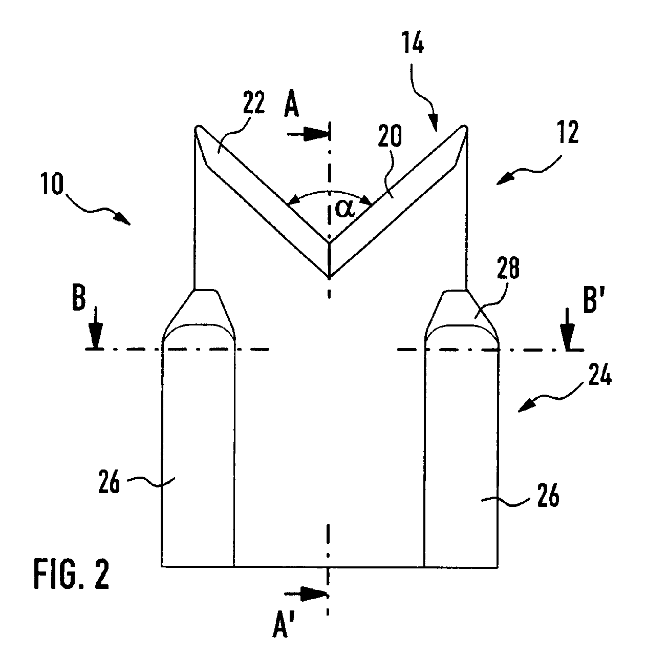
- Fig. 2 represents a side view of a preferred embodiment of a punching tool 10 according to the present invention.
- Punching tool 10 generally comprises a punching end12, the leading edge of which is formed as a cutting edge 14.
- the punching end 12 of the punching tool 10 has preferably an oblong cross section, wherein a central portion 16 of said cross section has a larger thickness T than the thickness t of the lateral portions 18 (see fig. 1).
- said cross section has a rounded rhombic cross section, i.e. a rhombic shape with rounded corners.
- the gradually increasing thickness (when seen from the outside to the center) of such a rhombic shape is best suited to compensate for the deformation characteristic of a tubular manifold. It will be appreciated, that the optimal ratio T/t of the rhombic shape depends from the tube material, the tube diameter and the dimensions of the slot to be formed.
- the cutting edge 14 comprises two adjacent branches 20 and 22, which form an angular recess or indent.
- the angle ⁇ between the two branches 20 and 22 is preferably optimized for the diameter and the gage of the tube.
- the punching tool Adjacent the punching end 12, the punching tool comprises a deformation portion 24 for forming a flared border at the lateral ends of the slot to be punched.
- the deformation portion 24 In the deformation portion 24, one bulge 26 is laterally arranged on each lateral portion of the punching tool (see also fig. 3). The function of this bulge is to deform the border of the punched hole into a flared lead-in especially at the two ends of the elongated slot.
- the shape of the bulges 26 is preferably optimized in order to provide a smooth transition between the flared lead-in at the lateral ends of the slot and the longitudinal lead-in. In the shown embodiment, the bulges 26 have a generally elliptical cross section (see fig. 4).
- the bulges Towards the punching end 12 of the punching tool, the bulges preferably comprise a section 28, tapering towards the punching end. This tapered section 28 ensures a smooth deformation of the border of the slot during the punching operation. It will be noted, that the bulges 26 are preferably arranged in a retracted position with respect to a cutting edge 14 of the punching tool 10. A favorable arrangement is such that the deformation means only enter the slot at the end of the lancing stroke, i.e. the deformation of the border is only achieved immediately before the movement of the punching tool is reversed. If the punching tool is retracted, the punching tool and the border immediately separate, so that the flared border will not be damaged during retraction.
Landscapes
- Engineering & Computer Science (AREA)
- Mechanical Engineering (AREA)
- Punching Or Piercing (AREA)
Abstract
Description
- The present invention generally relates to the manufacture of heat exchangers, e.g. for use in motor vehicle air conditioning systems, and more specifically to a punching tool for forming tube slots in a manifold of a heat exchanger.
- Motor vehicle heat exchangers usually comprise two header tanks or manifolds, which are aligned in a parallel arrangement, and flow tubes which extend in parallel between the two manifold tubes. Furthermore, fins are placed between the tubes for enhancing the heat transfer capacity of the flow tubes.
- The flow tubes have a generally oblong section. In order to assemble the heat exchanger, the ends of the flow tubes are aligned, simultaneously inserted into corresponding oblong slots in the manifold tubes and thereafter brazed thereto. In order to be able to simultaneously insert a plurality of flow tubes into corresponding slots of the manifold tubes, a high accuracy of the shape of the slots is required.
- The slots are formed in a punching operation, whereby a plurality of punching tools are simultaneously driven through the rounded wall of the manifold tube. During the punching operation, when a cutting edge of the punching tool is driven through the manifold tube material, the tube wall is deformed prior to be cut by said cutting edge. This deformation results in an inwardly rounded border of the slot, thus forming a flared lead-in for the flow tubes. Due to the rounded shape of the manifold tube, the deformation is much higher in the region of the center of the slot than at the ends of the slots.
- Some major suppliers of the automotive heat exchanger market are currently using punching tools, which have their faces contained in two parallel planes. It follows that the punching dies have a generally oblong cross section, comprising a flat center portion and two rounded lateral portions. The problem observed in the slot shape after a lancing operation with these known punching tools is the hour-glassed shape of the slot resulting from material strength reaction. This results in a distorted shape compared to the theoretical oblong slot suitable for the insertion of the flow tubes.
- The object of the present invention is to provide a punching tool which does not have the above described drawback.
- This object is achieved by a punching tool for forming elongated slots in a tubular wall according to claim 1. The punching tool comprises a punching end having a generally oblong cross section, said cross section comprising a central portion and two lateral portions. According to the invention, said central portion has a larger thickness than said lateral portions.
- During the punching operation with the present punching tool, the thicker center portion of the tool widens the slot in the region of its center. This mechanical widening of the slot compensates for the natural tube wall strength reaction so that the typical hour-glassed shape of the formed slot can be prevented. It follows that after the material reaction, the slot geometry is much closer to the theoretical oblong shape.
- In a preferred embodiment, said cross section of said punching end has a rounded rhombic shape, i.e. a rhombic shape with rounded corners. The gradually increasing thickness (when seen from the outside to the center) is best suited to compensate for the deformation characteristic of a tubular manifold. It will be appreciated, that the exact form of the cross section depends from the tube material, the tube diameter and the dimensions of the slot to be formed. If suitably designed, a punching toll having such a rhombic shape can effectively prevent any distortion of the slot form. It follows that with a punching tool of this kind, the slot geometry easily remains within a suitable tolerance range compatible with the insertion of the flow tubes and the brazing operation between the manifold and the flow tube.
- The deformation of the tube wall during punching is highest in the center portion and smallest in the outer lateral portions of the slot. It follows, that with a conventional punching tool, no natural flared lead-in for the flow tubes is formed in the lateral regions of the slot. In order to form a lead-in also in the lateral portions, a preferred embodiment of the punching tool comprises a deformation portion adjacent to said punching end, said deformation portion comprising deformation means for deforming said tubular wall at a border of said elongated slot. The deformation means is preferably located in those regions of the punching tool, in which the deformation of the tubular manifold wall is normally not sufficient in order to create a flared border. It follows, that deformation means are preferably located at the two lateral portions of the punching tool. It should be noted that the deformation means could also surround said deformation portion on its entire periphery. In this case the flared border can be specifically shaped on the entire periphery of the formed slot.
- In a possible embodiment, said deformation means comprise an enlargement which extends outwardly of said lateral portion of said deformation portion. Due to this deformation means, a lead-in is also created at the lateral ends of the oblong slots, thus simplifying the insertion of the flow tubes. It will be appreciated, that the presence of a lead-in on the entire periphery of the slot also enhances the brazing of the flow tubes on the manifold. In fact by filling the space between the flared border and the inserted flow tube with brazing material, a secure and tight mounting can be easily achieved.
- In order to ensure a smooth deformation of the border of the slot, said enlargement comprises advantageously a tapered section, said section tapering towards said punching end.
- The form of the enlargements is preferably chosen so that there is a smooth transition between the flared lead-in at the lateral ends of the slot and the longitudinal lead-in. In a preferred embodiment, the enlargements have e.g. a generally elliptical cross section.
- It has to be noted, that the deformation means are preferably arranged in a retracted position with respect to a cutting edge of the punching tool. A favorable arrangement is such that the deformation means only enter the slot at the end of the lancing stroke, i.e. the deformation of the border is only achieved immediately before the movement of the punching tool is reversed. If the punching tool is retracted, the punching tool and the border immediately separate, so that the flared border will not be damaged during retraction.
- A leading edge of said punching end is usually designed as a cutting edge. The cutting edge preferably comprising two branches forming an angular recess or indent, said recess being symmetrical about a central axis of said punching tool. The so formed lancing angle is advantageously optimized for the diameter and the gage of the tube.
- The present invention will be more apparent from the following description of a not limiting embodiment with reference to the attached drawings, wherein
- Fig.1: shows a typical cross section of an embodiment of a punching tool according to the invention;
- Fig.2: shows a side view of a punching tool;
- Fig.3: a section of the tool along the line A-A';
- Fig.4: a cross section of the tool along the line B-B'.
-
- Fig. 2 represents a side view of a preferred embodiment of a
punching tool 10 according to the present invention.Punching tool 10 generally comprises a punching end12, the leading edge of which is formed as acutting edge 14. - The punching
end 12 of thepunching tool 10 has preferably an oblong cross section, wherein acentral portion 16 of said cross section has a larger thickness T than the thickness t of the lateral portions 18 (see fig. 1). In the embodiment shown in fig. 1, said cross section has a rounded rhombic cross section, i.e. a rhombic shape with rounded corners. The gradually increasing thickness (when seen from the outside to the center) of such a rhombic shape is best suited to compensate for the deformation characteristic of a tubular manifold. It will be appreciated, that the optimal ratio T/t of the rhombic shape depends from the tube material, the tube diameter and the dimensions of the slot to be formed. - Referring again to fig. 2, the
cutting edge 14 comprises twoadjacent branches branches - Adjacent the
punching end 12, the punching tool comprises adeformation portion 24 for forming a flared border at the lateral ends of the slot to be punched. In thedeformation portion 24, onebulge 26 is laterally arranged on each lateral portion of the punching tool (see also fig. 3). The function of this bulge is to deform the border of the punched hole into a flared lead-in especially at the two ends of the elongated slot. The shape of thebulges 26 is preferably optimized in order to provide a smooth transition between the flared lead-in at the lateral ends of the slot and the longitudinal lead-in. In the shown embodiment, thebulges 26 have a generally elliptical cross section (see fig. 4). - Towards the punching
end 12 of the punching tool, the bulges preferably comprise asection 28, tapering towards the punching end. Thistapered section 28 ensures a smooth deformation of the border of the slot during the punching operation. It will be noted, that thebulges 26 are preferably arranged in a retracted position with respect to acutting edge 14 of thepunching tool 10. A favorable arrangement is such that the deformation means only enter the slot at the end of the lancing stroke, i.e. the deformation of the border is only achieved immediately before the movement of the punching tool is reversed. If the punching tool is retracted, the punching tool and the border immediately separate, so that the flared border will not be damaged during retraction.
Claims (8)
- Punching tool for forming elongated slots in a tubular wall, said punching tool comprising a punching end having a generally oblong cross section, said cross section comprising a central portion and two lateral portions, characterized in that said central portion has a larger thickness than said lateral portions.
- Punching tool according to claim 1, wherein said cross section of said punching end has a rounded rhombic shape.
- Punching tool according to any one of claims 1 or 2, comprising a deformation portion adjacent to said punching end, said deformation portion comprising deformation means for deforming said tubular wall at a border of said elongated slot.
- Punching tool according to 3, wherein said deformation means comprises an enlargement, said enlargement extending outwardly of said lateral portion of said deformation portion.
- Punching tool according to 4, wherein said enlargement comprises a tapered section, said section tapering towards said punching end.
- Punching toll according to any one of claims 4 or 5, wherein said enlargement has a generally elliptical cross section.
- Punching tool according to any one of the preceding claims, wherein a leading edge of said punching end is designed as a cutting edge, said cutting edge comprising two branches forming an angular recess, said recess being symmetrical about a central axis of said punching tool.
- Use of the punching tool according to any one of the preceding claims for forming tube slots in a manifold of a heat exchanger.
Applications Claiming Priority (2)
| Application Number | Priority Date | Filing Date | Title |
|---|---|---|---|
| LU90728 | 2001-02-12 | ||
| LU90728A LU90728B1 (en) | 2001-02-12 | 2001-02-12 | Punching tool for forming tube slots in a manifold of a heat exchanger |
Publications (2)
| Publication Number | Publication Date |
|---|---|
| EP1230997A1 true EP1230997A1 (en) | 2002-08-14 |
| EP1230997B1 EP1230997B1 (en) | 2008-04-09 |
Family
ID=19731967
Family Applications (1)
| Application Number | Title | Priority Date | Filing Date |
|---|---|---|---|
| EP20020001206 Expired - Lifetime EP1230997B1 (en) | 2001-02-12 | 2002-01-17 | Punching tool for forming tube slots in a manifold of a heat exchanger |
Country Status (4)
| Country | Link |
|---|---|
| US (1) | US20020108244A1 (en) |
| EP (1) | EP1230997B1 (en) |
| DE (1) | DE60225959T2 (en) |
| LU (1) | LU90728B1 (en) |
Families Citing this family (3)
| Publication number | Priority date | Publication date | Assignee | Title |
|---|---|---|---|---|
| HU231715B1 (en) | 2020-08-26 | 2025-10-28 | Modine Manufacturing Company | Sealing method for heat exchanger production |
| US11904421B2 (en) | 2020-08-26 | 2024-02-20 | Modine Manufacturing Company | Method of making a heat exchanger |
| US12422197B2 (en) | 2022-10-11 | 2025-09-23 | Modine Manufacturing Company | Method of making a heat exchanger |
Citations (5)
| Publication number | Priority date | Publication date | Assignee | Title |
|---|---|---|---|---|
| FR1445981A (en) * | 1965-08-31 | 1966-07-15 | Morris Motors Ltd | secondary surface heat exchanger |
| DE3316960A1 (en) * | 1982-05-17 | 1983-11-17 | VEB Blechverformungswerk Leipzig, DDR 7031 Leipzig | Bottom for the tank of a tubular heat exchanger, and tool for producing it |
| FR2665520A3 (en) * | 1990-07-31 | 1992-02-07 | Vaillant Sarl | Heat exchanger with combined fins |
| US5092397A (en) * | 1989-03-30 | 1992-03-03 | Autokuhler Gmbh & Co Kg | Fin for a heat exchanger and heat exchanging system using the fin |
| EP0903555A2 (en) * | 1997-09-23 | 1999-03-24 | Behr GmbH & Co. | Fin for heat exchanger and method for making holes in such a fin |
Family Cites Families (17)
| Publication number | Priority date | Publication date | Assignee | Title |
|---|---|---|---|---|
| US2776003A (en) * | 1955-09-14 | 1957-01-01 | Vogel Tool & Die Corp | Method and apparatus for cutting tubing |
| US3120143A (en) * | 1961-02-20 | 1964-02-04 | Lloyd A Kreider | Tube notching machine |
| US3320843A (en) * | 1965-02-19 | 1967-05-23 | Gloucester Eng Co Inc | Punching device |
| US3721144A (en) * | 1970-02-25 | 1973-03-20 | Mitsubishi Monsanto Chem | Punching tool |
| US3996832A (en) * | 1975-04-10 | 1976-12-14 | Standard Oil Company (Indiana) | Punch for producing holes in foamed thermoplastic containers |
| US4494426A (en) * | 1983-05-20 | 1985-01-22 | Hartzell John C | Punch with removable blade |
| AU91693S (en) * | 1983-10-24 | 1986-04-10 | A punch | |
| US4569256A (en) * | 1984-09-11 | 1986-02-11 | Edward Pepper | Method of making a seamless punch |
| JPH01215413A (en) * | 1988-02-24 | 1989-08-29 | Sanko Kogyo Kk | Forming method for groove-shaped notch on hollow square pipe |
| US4932129A (en) * | 1988-12-05 | 1990-06-12 | Penetrators, Inc. | Casing punch for wells |
| US4974436A (en) * | 1989-02-24 | 1990-12-04 | Sanko Industries Limited | Cutting tool to facilitate bending of hollow tubing |
| US5778806A (en) * | 1990-12-26 | 1998-07-14 | Ralph's Industrial Sewing Machine Company | Sewing and material removal assembly |
| US5183053A (en) * | 1991-04-12 | 1993-02-02 | Acuderm, Inc. | Elliptical biopsy punch |
| US5507765A (en) * | 1994-04-28 | 1996-04-16 | Mott; James B. | Punch-type surgical instrument for skin incision, set of parts for making such an instrument of selectably variable size, and blade unit for such instrument |
| US5570700A (en) * | 1994-10-03 | 1996-11-05 | Vogeler; Douglas M. | Elliptical biopsy punch |
| US5730038A (en) * | 1995-01-25 | 1998-03-24 | Acco Usa, Inc. | Configuration for paper punch pin |
| US6058605A (en) * | 1997-07-30 | 2000-05-09 | The Budd Company | Rectangular tube trimming process and apparatus |
-
2001
- 2001-02-12 LU LU90728A patent/LU90728B1/en active
-
2002
- 2002-01-17 EP EP20020001206 patent/EP1230997B1/en not_active Expired - Lifetime
- 2002-01-17 DE DE2002625959 patent/DE60225959T2/en not_active Expired - Lifetime
- 2002-01-29 US US10/060,917 patent/US20020108244A1/en not_active Abandoned
Patent Citations (5)
| Publication number | Priority date | Publication date | Assignee | Title |
|---|---|---|---|---|
| FR1445981A (en) * | 1965-08-31 | 1966-07-15 | Morris Motors Ltd | secondary surface heat exchanger |
| DE3316960A1 (en) * | 1982-05-17 | 1983-11-17 | VEB Blechverformungswerk Leipzig, DDR 7031 Leipzig | Bottom for the tank of a tubular heat exchanger, and tool for producing it |
| US5092397A (en) * | 1989-03-30 | 1992-03-03 | Autokuhler Gmbh & Co Kg | Fin for a heat exchanger and heat exchanging system using the fin |
| FR2665520A3 (en) * | 1990-07-31 | 1992-02-07 | Vaillant Sarl | Heat exchanger with combined fins |
| EP0903555A2 (en) * | 1997-09-23 | 1999-03-24 | Behr GmbH & Co. | Fin for heat exchanger and method for making holes in such a fin |
Also Published As
| Publication number | Publication date |
|---|---|
| DE60225959T2 (en) | 2009-07-02 |
| DE60225959D1 (en) | 2008-05-21 |
| LU90728B1 (en) | 2002-08-13 |
| US20020108244A1 (en) | 2002-08-15 |
| EP1230997B1 (en) | 2008-04-09 |
Similar Documents
| Publication | Publication Date | Title |
|---|---|---|
| JP7383687B2 (en) | Collection box and corresponding heat exchanger | |
| EP0584993A1 (en) | Heat exchanger | |
| EP3591324B1 (en) | Micro-channel heat exchanger | |
| JP2006522306A (en) | Heat transfer body | |
| CN104769382B (en) | Heat exchanger assemblies | |
| US20040182558A1 (en) | Header for use in heat exchanger, heat exchanger and method for manufacturing the same | |
| EP1795853B1 (en) | A heat exchanger and a method of manufacturing the same. | |
| US9174266B2 (en) | Manifold bending support | |
| US5275236A (en) | Connecting tube for a heat exchanger fluid header, and a fluid header having such a connecting tube | |
| US6739386B2 (en) | Heat exchanger with cut tubes | |
| EP1230997A1 (en) | Punching tool for forming tube slots in a manifold of a heat exchanger | |
| US6668916B2 (en) | Flat tube block heat exchanger | |
| US7124805B2 (en) | Tube feature for limiting insertion depth into header slot | |
| EP1219913A2 (en) | Improved side piece for heat exchangers | |
| EP1850076A2 (en) | Refrigerant condenser equipped with receiver | |
| JPH06159985A (en) | Heat exchanger and its preparation | |
| EP1239253A2 (en) | Heat exchanger | |
| JP4239840B2 (en) | Mouth expansion jig for heat exchanger tubes | |
| JP2002357395A (en) | Header for heat exchanger, heat exchanger, and their manufacturing methods | |
| JP2005114199A (en) | Header for heat exchanger and manufacturing method thereof | |
| JP2005121296A (en) | Brazed flat tube | |
| EP1515109A2 (en) | A heat exchanger and method of manufacturing of a heat exchanger header tank | |
| JP4324912B2 (en) | Heat exchanger header manufacturing method and heat exchanger header | |
| JP2017528679A (en) | Heat exchanger | |
| JPH067871A (en) | Manufacture of heat exchanger |
Legal Events
| Date | Code | Title | Description |
|---|---|---|---|
| PUAI | Public reference made under article 153(3) epc to a published international application that has entered the european phase |
Free format text: ORIGINAL CODE: 0009012 |
|
| AK | Designated contracting states |
Kind code of ref document: A1 Designated state(s): AT BE CH CY DE DK ES FI FR GB GR IE IT LI LU MC NL PT SE TR |
|
| AX | Request for extension of the european patent |
Free format text: AL;LT;LV;MK;RO;SI |
|
| 17P | Request for examination filed |
Effective date: 20020909 |
|
| AKX | Designation fees paid |
Designated state(s): DE FR GB IT |
|
| 17Q | First examination report despatched |
Effective date: 20061204 |
|
| GRAP | Despatch of communication of intention to grant a patent |
Free format text: ORIGINAL CODE: EPIDOSNIGR1 |
|
| GRAS | Grant fee paid |
Free format text: ORIGINAL CODE: EPIDOSNIGR3 |
|
| GRAA | (expected) grant |
Free format text: ORIGINAL CODE: 0009210 |
|
| AK | Designated contracting states |
Kind code of ref document: B1 Designated state(s): DE FR GB IT |
|
| REG | Reference to a national code |
Ref country code: GB Ref legal event code: FG4D |
|
| REF | Corresponds to: |
Ref document number: 60225959 Country of ref document: DE Date of ref document: 20080521 Kind code of ref document: P |
|
| ET | Fr: translation filed | ||
| PLBE | No opposition filed within time limit |
Free format text: ORIGINAL CODE: 0009261 |
|
| STAA | Information on the status of an ep patent application or granted ep patent |
Free format text: STATUS: NO OPPOSITION FILED WITHIN TIME LIMIT |
|
| 26N | No opposition filed |
Effective date: 20090112 |
|
| GBPC | Gb: european patent ceased through non-payment of renewal fee |
Effective date: 20090117 |
|
| PG25 | Lapsed in a contracting state [announced via postgrant information from national office to epo] |
Ref country code: GB Free format text: LAPSE BECAUSE OF NON-PAYMENT OF DUE FEES Effective date: 20090117 |
|
| REG | Reference to a national code |
Ref country code: DE Ref legal event code: R082 Ref document number: 60225959 Country of ref document: DE Representative=s name: BRP RENAUD UND PARTNER MBB, DE Ref country code: DE Ref legal event code: R081 Ref document number: 60225959 Country of ref document: DE Owner name: MAHLE INTERNATIONAL GMBH, DE Free format text: FORMER OWNER: DELPHI TECHNOLOGIES, INC., TROY, MICH., US Ref country code: DE Ref legal event code: R082 Ref document number: 60225959 Country of ref document: DE Representative=s name: BRP RENAUD UND PARTNER MBB RECHTSANWAELTE PATE, DE |
|
| REG | Reference to a national code |
Ref country code: FR Ref legal event code: PLFP Year of fee payment: 15 |
|
| REG | Reference to a national code |
Ref country code: FR Ref legal event code: PLFP Year of fee payment: 16 |
|
| REG | Reference to a national code |
Ref country code: FR Ref legal event code: PLFP Year of fee payment: 17 |
|
| REG | Reference to a national code |
Ref country code: FR Ref legal event code: TP Owner name: MAHLE INTERNATIONAL GMBH, DE Effective date: 20180103 |
|
| PGFP | Annual fee paid to national office [announced via postgrant information from national office to epo] |
Ref country code: FR Payment date: 20190130 Year of fee payment: 18 Ref country code: IT Payment date: 20190121 Year of fee payment: 18 |
|
| PGFP | Annual fee paid to national office [announced via postgrant information from national office to epo] |
Ref country code: DE Payment date: 20190401 Year of fee payment: 18 |
|
| REG | Reference to a national code |
Ref country code: DE Ref legal event code: R119 Ref document number: 60225959 Country of ref document: DE |
|
| PG25 | Lapsed in a contracting state [announced via postgrant information from national office to epo] |
Ref country code: DE Free format text: LAPSE BECAUSE OF NON-PAYMENT OF DUE FEES Effective date: 20200801 |
|
| PG25 | Lapsed in a contracting state [announced via postgrant information from national office to epo] |
Ref country code: IT Free format text: LAPSE BECAUSE OF NON-PAYMENT OF DUE FEES Effective date: 20200117 |
|
| PG25 | Lapsed in a contracting state [announced via postgrant information from national office to epo] |
Ref country code: FR Free format text: LAPSE BECAUSE OF NON-PAYMENT OF DUE FEES Effective date: 20200131 |