EP1229766A2 - Atomic fountain apparatus - Google Patents
Atomic fountain apparatus Download PDFInfo
- Publication number
- EP1229766A2 EP1229766A2 EP02001833A EP02001833A EP1229766A2 EP 1229766 A2 EP1229766 A2 EP 1229766A2 EP 02001833 A EP02001833 A EP 02001833A EP 02001833 A EP02001833 A EP 02001833A EP 1229766 A2 EP1229766 A2 EP 1229766A2
- Authority
- EP
- European Patent Office
- Prior art keywords
- atoms
- laser
- laser beam
- collimation
- generating section
- Prior art date
- Legal status (The legal status is an assumption and is not a legal conclusion. Google has not performed a legal analysis and makes no representation as to the accuracy of the status listed.)
- Withdrawn
Links
- 0 CC(C)N(C*)** Chemical compound CC(C)N(C*)** 0.000 description 1
Images




Classifications
-
- G—PHYSICS
- G21—NUCLEAR PHYSICS; NUCLEAR ENGINEERING
- G21K—HANDLING OF PARTICLES OR IONISING RADIATION NOT OTHERWISE PROVIDED FOR; IRRADIATION DEVICES; GAMMA RAY OR X-RAY MICROSCOPES
- G21K1/00—Arrangements for handling particles or ionising radiation, e.g. focusing or moderating
- G21K1/30—Arrangements for handling particles or ionising radiation, e.g. focusing or moderating for confining neutral particles or handling confined neutral particles, e.g. atom traps
-
- H—ELECTRICITY
- H05—ELECTRIC TECHNIQUES NOT OTHERWISE PROVIDED FOR
- H05H—PLASMA TECHNIQUE; PRODUCTION OF ACCELERATED ELECTRICALLY-CHARGED PARTICLES OR OF NEUTRONS; PRODUCTION OR ACCELERATION OF NEUTRAL MOLECULAR OR ATOMIC BEAMS
- H05H3/00—Production or acceleration of neutral particle beams, e.g. molecular or atomic beams
- H05H3/04—Acceleration by electromagnetic wave pressure
Definitions
- This invention relates to an atomic fountain apparatus, especially to a cesium atomic fountain apparatus.
- FIG. 9 shows the operating principle of a prior art beam-type cesium frequency standard.
- reference numeral 80 refers to a container
- 81 refers to a microwave resonator
- 82 refers to a cesium atomic-beam
- 83 refers to a microwave, respectively.
- the cesium atomic beam 82 When the cesium atomic beam 82 is input into the microwave resonator 81, the cesium atomic beam 82 interacts with the microwave 83, causing the cesium atoms having two energy levels to resonate with the frequency of the microwave. The cesium atoms are allowed to jump from one energy level to the other energy level by the resonance.
- the frequency of the microwave resonating with the cesium atoms is approximately 9.192 ⁇ 10 9 Hz (approximately 9 GHz) which provides a standard of time for an atomic clock. With this standard, an error of one second is caused in several millions of year (10 14 ⁇ 10 15 seconds).
- this state can be detected, for example, by irradiating a light.
- the atoms do not absorb the light.
- the light is absorbed and fluorescent light is emitted.
- the fluorescent light is not emitted.
- each of the energy levels of cesium atom which usually take discrete values, has a uncertainty width, which tends to be reduced with increases of interaction time (measuring time). Having an uncertainty in each energy state has an uncertain width may cause the frequency fluctuation within a certain width of Lorentz distribution, posing an accuracy problem.
- the atomic fountain type is characterized in that the spectral line width can be very narrow and the Doppler effect can be reduced by using atoms whose velocity ( ⁇ 5m/sec) is considerably slower than that (250 m/sec) in the beam-type frequency standards.
- Slow atoms can be realized by laser cooling.
- the laser cooling is a cooling method of atoms by using forces that the atoms receive, when absorbing or emitting a light.
- the cesium atoms can be cooled to temperatures near absolute zero, using the laser cooling.
- the atom absorbs the light and receives a force in the direction of the light traveling, and ground state electrons of the atom are excited. The electrons fall to the ground state, emitting fluorescent light uniformly in all direction.
- the momentum is always conservative in each direction, which means the atom receives a force in the reverse direction of the laser irradiating direction. Using the effect, the movement of the atom can be controlled to be still by laser irradiating from each positive and negative directions of x, y and z axis .
- FIG. 10 A,B and C shows drawings explaining the atomic fountain type.
- a certain velocity is given to an atom ⁇
- a laser beam of a frequency of ⁇ - ⁇ ⁇ + ⁇ N is applied to the atom in one direction
- another laser beam of a frequency of ⁇ - ⁇ ⁇ - ⁇ N is applied to it in the other direction, as shown in FIG. 10 A.
- the velocity of ⁇ 0 is given to the atom ⁇ .
- FIG.12 C shows the atomic fountain of the tossed cesium atoms up, which pass through a microwave generator.
- FIG. 11 is an external view of a conventional atomic fountain type cesium frequency standard.
- reference numeral 90 refers to a magnetic shield
- 91 refers to a uniform field generator
- 92 refers to a microwave resonator
- 93 refers to a magneto-optical trap
- 94 refers to an input section of a laser beam applied to cesium atoms in six directions in a magneto-optical trap
- 95 refers to a signal detector
- 96 refers to an ion pump, respectively.
- Tossing the cesium atoms in the vertical direction can be realized by a resultant forces of vertical direction components of forces caused by laser beams from four directions of the input sections of the laser beam 94.
- the atomic fountain is accomplished by three steps of laser capture (trap), cooling and vertical launch.
- a magneto-optical trap 93 which traps cesium atoms by irradiating with laser beams in six directions in an inhomogeneous magnetic field which has a minimum magnetic field, is used.
- the captured atoms are cooled by polarized gradient cooling to a temperature below the Doppler limit (laser cooling).
- Polarized gradient cooling is carried out by using an optical molasses comprising six laser beams having the same frequency.
- a moving molasses can be realized, that is, the atoms can be tossed upward while maintaining very low temperatures.
- the atoms pass twice through the microwave resonator 92 disposed on the upper part, once the way up and once the way down, and a Ramsey resonance signal is observed in the signal detector 95 placed under the magneto optical trap 93.
- a spectral line width as narrow as approximately 1 Hz can be obtained because the interaction time is a period the atoms float in the microwave resonator 92.
- the signal detector 95 detects only those atoms which fall down and passing through the hole on the microwave resonator 92 again among the atoms which have been launched and passed through the hole.
- the conventional atomic fountain type has an essential problem that the detected spectrum signal is so small that the S/N ratio is not enough.
- An object of the present invention is to provide an atomic fountain apparatus that can improve the S/N ratio of the spectrum by suppressing the diffusion of the launched atoms in the horizontal direction.
- the launched atoms are irradiated with a laser beam in the direction of the launched atoms to collimate the atoms. Irradiated continuously with the collimating laser beam, the atoms hardly diffuse horizontally, however the presence of the field of light may shift the observed frequency for measuring atoms. It is a problem to be solved.
- Another object of the present invention is to solve the problem for the atomic fountain apparatus.
- Atomic fountain apparatus of the present invention comprises a collimation laser generating section for generating a laser beam of a frequency that does not resonate with the atoms.
- the collimation laser beam output by the collimation laser generating section is applied to the atoms in the direction of the tossed atoms.
- an atomic fountain apparatus for laser trapping, cooling and tossing atoms with a plurality of laser beams and comprising a microwave generator.
- the atoms passes upward and fall back through a microwave resonator are observed.
- the atomic fountain apparatus comprises a collimation laser generating section for generating a laser beam of a frequency that does not resonate with the atoms. Further it comprises a switch for controlling on and off of the irradiation of the laser beam output from the collimation laser generating section.
- the collimation laser beam output by the collimation laser generating section is applied in the direction of the tossed atoms. The switch is turned off before the atoms reaches the microwave resonator.
- the present invention allows almost all the launched atoms to return to the hole of the microwave resonator by reducing the horizontal velocity component of the atomic fountain using the dipole force generated by the electrical field of the laser beam.
- the S/N ratio is improved by the collimation of the atoms.
- the velocity component in the direction vertical to laser beam is suppressed using a dipole force caused with a laser beam, so it is possible to improve the S/N ratio and consistently guarantee an accuracy of one second error in several million years
- FIG. 1 shows the operating principle of the present invention.
- reference numeral 1 refers to a laser trap-cooling section
- 1a shows a plurality of cesium atoms
- 2 refers to a microwave resonator
- 3 refers to a collimation laser beam in a direction of the launched atoms.
- the collimation laser beam prevents the launched atoms to diffuse in the direction vertical to the launched direction.
- 4 refers to a switch to turning on and off the laser generated by the collimation laser generating section
- 5 refers to a collimation laser generating section for generating the collimation laser beam 3.
- the environment where the cesium atoms 1a exist and move, such as the laser trap-cooling section 1 is kept almost vacuum.
- Atoms receive two forces from the photons of laser beam, that is, one is scattering force (i), and another is dipole force (ii).
- the scattering force (i) is a force generated when the kinetic momentum of atoms varies by the kinetic momentum as the atoms absorb and release photons. It is not a conservative force, and is used mainly for laser cooling and also for acceleration.
- the dipole force (ii) is caused by the second order Stark effect, which is produced as atoms is influenced by the electric field of a light.
- a potential U expressed by the following equation (1) is caused, where ⁇ is a polarizability of atoms with respect to a d-c electric field.
- E is an electric field.
- the phase space volume (a product of velocity distribution and displacement distribution) does not change. It is possible, however, to narrow the velocity distribution while expanding the positional distribution.
- the velocity components vertical to the laser beam is reduced by the dipole force caused with the laser beam.
- Atoms comprise atomic nuclei and electrons, and produce induced electric dipoles when exposed to an electric field by a laser beam. This dipole force acts as an attraction force, and the atoms are attracted toward the stronger power region of the laser beam.
- FIG. 2 A shows a power distribution to distance from a beam center of a laser beam for collimating the atoms of atomic fountain in one dimensional model.
- the power distribution has characteristics of Gaussian distribution, as expressed by the following equations (2) and (3) where P denotes a power density, P 0 is the maximum value of the power density, x is a distance, ⁇ x is the radius of the laser beam, and E is an electric field.
- the force of the atoms received with the laser beam can be expressed by the following equation (4). - ( ⁇ E 0 2 / ⁇ x ) ⁇ x ⁇ exp[- x 2 /( ⁇ x ) 2 ]
- the position x(t) in this case can be expressed by the following equation (6) where x(0) is the initial position and v x (0) is the initial velocity.
- x ( t ) x (0)cos ⁇ t + [ v x (0)/ ⁇ ]sin ⁇ t
- v x ( t ) v x (0)cos ⁇ t - x (0) ⁇ sin ⁇ t
- the position of the atoms changes in the direction vertical to the laser beam as shown in FIG. 2B, and the velocity of the atoms changes with respect to time as shown in FIG.2C with the dipole force of the laser beam.
- the cesium atoms 1a are trapped and cooled in the laser trap-cooling section 1 using the conventional atomic-fountain type technology.
- the laser beam for collimation of the atoms is emitted from the collimation laser generator 5 by turning the switch 4, and at nearly same time, the cooled atoms are tossed and at the same time.
- the atoms 1a are tossed upward in parallel with the traveling direction of the light without dispersed, because of the dipole force caused with the electric field of the laser beam.
- the switch 4 is turned off to stop the output of the collimation laser beam.
- Each of the cesium atoms 1a is pushed up with the velocity at that time in the vertical direction.
- the velocity at that time is set at a level at which the atoms can pass through the hole of the microwave resonator 2 placed above the laser trap.
- the cesium atoms 1a pass through the hole of the microwave resonator 2 upward from the lower side, and as they lose their impetus, the atoms then fall back down by the gravity through the hole of the microwave resonator 2. Since the cesium atoms 1a do not diffuse in the horizontal direction during the round trip in the up and down direction, the atoms tossed upward and passed through the hole can fall back down through the hole with high accuracy (approximately 85% in the calculation).
- the on and off of the switch is repeated with a cycle predetermined so that the switch 4 is changed from the ON to the OFF in lapse of a settled time, and further changed to ON in a settled time.
- FIG. 3 shows a configuration of an embodiment of the present invention
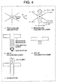
- FIG. 4 shows operation steps of the embodiment
- FIG. 5 A and FIG.5 B show a diagram of changes of the position and velocity of atoms respectively with the lapse of time.
- reference numeral 10 refers to a body part of the cesium atomic fountain type frequency standard
- 11 refers to a microwave resonator (corresponding to reference numeral 2 of FIG.1)
- 12 refers to a mirror reflecting laser beam
- 13 refers to a window through which the laser beam goes out and comes in
- 14 refers to a laser trap-cooling section for trapping, cooling and tossing up cesium atoms (corresponding to reference numeral 1 of FIG.
- 15a ⁇ 15f refer to laser beam input portions through which the cesium atoms are irradiated with the laser beams from six directions for trapping the atoms
- 16 refers to a collimation laser beam input portion for launching the atoms
- 17 refers to a switch for turning on and off the collimation laser beam (corresponding to reference numeral 4 of FIG. 1)
- 18 refers to a collimation laser beam generating section (corresponding to reference numeral 5 of FIG. 1)
- 19 refers to a collimation laser beam.
- Trapping, cooling and tossing the cesium atoms in the construction of FIG.3 are same with those in apparatus of FIG.11. Same laser sources are used for the laser trapping, cooling and tossing the atoms. Changing the laser irradiating frequency according to trapping, cooling and tossing can be implemented with an acoustooptical element.
- a titanium-sapphire laser can be used, but other types of laser can also be used. Note that the signal detecting section is omitted in the figure 3.
- the cesium atom 1a (including a plurality of atoms) is trapped and cooled in the laser trap-cooling section 14 with the laser beam from each of the input portions 15a ⁇ 15f, as shown in “ i "of FIG. 4. Thereafter, the cesium atom 1a is tossed up, irradiated on the directions with respective frequencies set as shown in "ii" of FIG. 4. At the nearly same time, the switch 17 is turned on to irradiate the laser trap-cooling section 14 from underneath with the laser emitted from the collimation laser generating section 18. The launched cesium atom is gradually decelerated in the horizontal direction (see “iii" of FIG. 4).
- FIG. 5 A shows changes in the traveling distance of the cesium atoms with the lapse of time.
- the ordinate represents the horizontal distance from the centerline of the atom wave guide, and the abscissa represents time. After the lapse of the time T, the horizontal distance shows no change, becoming constant. At this time T, the switch 17 for controlling the output of the collimation laser is turned off.
- FIG. 5 B shows changes of the velocity of the cesium atoms in accordance with the lapse of time corresponding to the time of FIG.5A. It is shown that the velocity falls to zero after the lapse of the time T at which the switch 17 has been turned off.
- the collimation laser beam should preferably be no resonant to prevent the scattering caused by the absorption and emission of the beam.
- the laser requires a great power to obtain a sufficient dipole force for the reason of no resonant.
- a CO 2 laser for the no re sonant for example, requires a high power as high as about 360 W.
- a titanium sapphire laser is used as a laser for generating a wave length near to the wave length of the cesium atom.
- This titanium sapphire laser has an output of 300 mW, a detuning frequency of 1 THz (terahertz: 10 12 Hz), and a spot size of 3 mm.
- FIG. 6 is a graph showing relations between the final velocity (v x (T)) and the initial velocity (v x (0)), the ordinate representing the final velocity when the switch is turned off, and the abscissa representing the initial velocity.
- FIG. 7 is the kinetic energy distribution of the one dimensional model, the abscissa being kinetic energy (in nK), and the ordinate being distribution (in percentage).
- the characteristic shown by a sold line in FIG. 7 is the energy distribution of thee present invention where the collimation laser beam is irradiated 0.1sec and the switch is turned off at the time. The characteristic shows that most of the atoms are distributed in areas of low kinetic energy.
- the characteristic shown in a dotted line is the distribution of energy in the case where the collimation laser beam was not irradiated , the distribution is approximately uniform in the level of about 2.6 ⁇ K.
- Equation 10 the electric field E(r) can be expressed by Equation (10), and the dynamic equation in the radial direction is expressed by Equation (11).
- L in Equation (11) denotes an angular momentum component parallel to the laser beam, and L 2 /r 3 denotes a centrifugal force.
- Equation (13) The distribution of r(0) and v r (0) (expressed as ⁇ r (0), ⁇ V r (0)) is expressed by Equations (13) and (14) where ⁇ r is 0.25 mm, ⁇ v is 1.8 cm/s (2.6 ⁇ K).
- the kinetic energy distribution of the two dimensional model calculated above is shown in FIG. 8.
- the abscissa and ordinate in FIG. 8 represent kinetic energy and distribution, respectively.
- infrared laser beam which is non resonant
- collimation laser beam for causing the dipole force
- a kinetic energy after the interaction of the atom and the photon is lower than single photon recoil, because the heating effect due to scattering can be avoided.
- the required apparatus may be simpler than that for Raman cooling.
Landscapes
- Physics & Mathematics (AREA)
- Spectroscopy & Molecular Physics (AREA)
- Engineering & Computer Science (AREA)
- General Engineering & Computer Science (AREA)
- High Energy & Nuclear Physics (AREA)
- Electromagnetism (AREA)
- Plasma & Fusion (AREA)
- Lasers (AREA)
- Stabilization Of Oscillater, Synchronisation, Frequency Synthesizers (AREA)
Abstract
Description









Claims (7)
- Atomic fountain apparatus trapping, cooling and tossing upward atoms with a plurality of laser beams comprising:wherein the collimation laser beam output by the collimation laser generating section is applied to the atoms in the direction of the tossed atoms to collimate the tossed atoms..a collimation laser generating section for generating laser beam of a frequency that does not resonate with the atoms,
- Atomic fountain apparatus in claim 1 comprising:wherein the switch is turned on to out put the laser beam by the collimation laser generating section at the time tossing the atoms, and turned off at the time that horizontal velocity components of the atoms become nearly zero.a switch for controlling off of irradiation of the laser beam output from the collimation laser generating section;
- An atomic fountain apparatus trapping, cooling and tossing upward atoms with a plurality of laser beams, and comprising a microwave resonator, wherein the atoms pass upward fall back through a microwave resonator comprising:wherein the collimation laser beam output by the collimation laser generating section is applied to the atoms in the direction of the tossed atoms, and the switch is turned off before the atoms reaches the microwave resonator.a collimation laser generating section for generating laser beam of a frequency that does not resonate with the atoms; anda switch for controlling on and off of the light output from the collimation laser generating section;
- An atomic fountain apparatus in claim 3 : wherein the atoms are cesium.
- A n atomic fountain apparatus in claim 4: wherein the cesium atoms passing through the microwave resonator without dispersing from the atomic wave guide even after the switch has been turned off.
- An atomic fountain apparatus in claim 4: wherein a carbon dioxide laser of a frequency that does not resonate with the cesium atoms is used as the laser beam output from the collimation laser generating section.
- An atomic fountain apparatus in claim 4: wherein
a titanium sapphire laser is used as the laser beam output from the collimation laser generating section.
Applications Claiming Priority (2)
| Application Number | Priority Date | Filing Date | Title |
|---|---|---|---|
| JP2001025191 | 2001-02-01 | ||
| JP2001025191A JP3418732B2 (en) | 2001-02-01 | 2001-02-01 | Cesium atom spring collimation device |
Publications (2)
| Publication Number | Publication Date |
|---|---|
| EP1229766A2 true EP1229766A2 (en) | 2002-08-07 |
| EP1229766A3 EP1229766A3 (en) | 2004-08-04 |
Family
ID=18890225
Family Applications (1)
| Application Number | Title | Priority Date | Filing Date |
|---|---|---|---|
| EP02001833A Withdrawn EP1229766A3 (en) | 2001-02-01 | 2002-01-26 | Atomic fountain apparatus |
Country Status (3)
| Country | Link |
|---|---|
| US (1) | US6635867B2 (en) |
| EP (1) | EP1229766A3 (en) |
| JP (1) | JP3418732B2 (en) |
Cited By (1)
| Publication number | Priority date | Publication date | Assignee | Title |
|---|---|---|---|---|
| CN112556676A (en) * | 2020-11-30 | 2021-03-26 | 华中科技大学 | Device for adjusting motion parameters of atomic fountain |
Families Citing this family (15)
| Publication number | Priority date | Publication date | Assignee | Title |
|---|---|---|---|---|
| JP3855035B2 (en) * | 2001-01-29 | 2006-12-06 | 独立行政法人理化学研究所 | Laser cooling method and apparatus for atoms |
| US6684645B2 (en) * | 2001-04-04 | 2004-02-03 | The Board Of Trustees Of The Leland Stamford Junior University | Cooling by resonator-induced coherent scattering of radiation |
| JP4766420B2 (en) * | 2005-05-31 | 2011-09-07 | 独立行政法人情報通信研究機構 | Magneto-optical trap device for neutral atoms |
| US7709807B2 (en) * | 2007-05-31 | 2010-05-04 | United States Of America As Represented By The Secretary Of Commerce, The National Institute Of Standards And Technology | Magneto-optical trap ion source |
| FR2928725B1 (en) * | 2008-03-12 | 2010-04-09 | Centre Nat Rech Scient | COLD ATOMIC INTERFEROMETRIC SENSOR |
| JP5665042B2 (en) * | 2010-09-01 | 2015-02-04 | 独立行政法人情報通信研究機構 | Reference signal generator and reference signal generation method using phase-preserving Ramsey method |
| US9062973B2 (en) | 2011-01-31 | 2015-06-23 | Northrop Grumman Guidance And Electronics Company, Inc. | Atom beam gyroscope |
| US9134450B2 (en) | 2013-01-07 | 2015-09-15 | Muquans | Cold atom gravity gradiometer |
| US10330459B1 (en) | 2017-03-01 | 2019-06-25 | AOSense, Inc. | Light pulse atom interferometer velocity reference |
| CN108983591B (en) * | 2018-08-30 | 2020-04-03 | 中国科学院上海光学精密机械研究所 | Microwave cavity integrating laser cooling, state selection and atom detection |
| US11467330B1 (en) | 2018-10-23 | 2022-10-11 | Government Of The United States As Represented By The Secretary Of The Air Force | One beam mirror magneto-optical trap chamber |
| US11079230B2 (en) | 2019-05-10 | 2021-08-03 | Northrop Grumman Systems Corporation | Fiber-optic gyroscope (FOG) assembly |
| CN111863306B (en) * | 2020-07-22 | 2022-06-17 | 中国科学院精密测量科学与技术创新研究院 | Large beam cold atom source with adjustable speed |
| CN118633214A (en) * | 2022-02-01 | 2024-09-10 | 国立研究开发法人理化学研究所 | Magneto-optical trap device, physical package, physical package for optical lattice clock, physical package for atomic clock, physical package for atomic interferometer, physical package for quantum information processing equipment and physical package system |
| CN114689556B (en) * | 2022-03-23 | 2025-06-24 | 北京无线电计量测试研究所 | A device and method for measuring thermal atom beam distribution |
Family Cites Families (5)
| Publication number | Priority date | Publication date | Assignee | Title |
|---|---|---|---|---|
| FR2644315B1 (en) * | 1989-03-13 | 1991-05-24 | Oscilloquartz Sa | MICROWAVE INTERACTION MODULE, IN PARTICULAR FOR AN ATOMIC OR MOLECULAR JET RESONATOR |
| US5528028A (en) * | 1990-06-01 | 1996-06-18 | Chu; Steven | Frequency standard using an atomic stream of optically cooled atoms |
| US5338930A (en) * | 1990-06-01 | 1994-08-16 | Research Corporation Technologies | Frequency standard using an atomic fountain of optically trapped atoms |
| JPH06112551A (en) * | 1992-09-25 | 1994-04-22 | Nippon Telegr & Teleph Corp <Ntt> | Slow atom beam generation method and its equipment |
| JP2001068054A (en) * | 1999-08-27 | 2001-03-16 | Kumayasu Yoshii | Atomic beam spectrographic device |
-
2001
- 2001-02-01 JP JP2001025191A patent/JP3418732B2/en not_active Expired - Lifetime
-
2002
- 2002-01-22 US US10/051,105 patent/US6635867B2/en not_active Expired - Fee Related
- 2002-01-26 EP EP02001833A patent/EP1229766A3/en not_active Withdrawn
Cited By (2)
| Publication number | Priority date | Publication date | Assignee | Title |
|---|---|---|---|---|
| CN112556676A (en) * | 2020-11-30 | 2021-03-26 | 华中科技大学 | Device for adjusting motion parameters of atomic fountain |
| CN112556676B (en) * | 2020-11-30 | 2022-09-13 | 华中科技大学 | Device for adjusting motion parameters of atomic fountain |
Also Published As
| Publication number | Publication date |
|---|---|
| JP3418732B2 (en) | 2003-06-23 |
| JP2002232041A (en) | 2002-08-16 |
| US20020125418A1 (en) | 2002-09-12 |
| US6635867B2 (en) | 2003-10-21 |
| EP1229766A3 (en) | 2004-08-04 |
Similar Documents
| Publication | Publication Date | Title |
|---|---|---|
| US6635867B2 (en) | Atomic fountain apparatus | |
| Condon et al. | All-optical Bose-Einstein condensates in microgravity | |
| Weiner et al. | Experiments and theory in cold and ultracold collisions | |
| Balykin et al. | Quantum-state-selective mirror reflection of atoms by laser light | |
| Phillips et al. | Laser cooling and electromagnetic trapping of neutral atoms | |
| Aminoff et al. | Cesium atoms bouncing in a stable gravitational cavity | |
| Haroche et al. | Cavity Quantum | |
| Lett et al. | Optical molasses | |
| Foot | Laser cooling and trapping of atoms | |
| Schünemann et al. | Magneto-optic trapping of lithium using semiconductor lasers | |
| US5338930A (en) | Frequency standard using an atomic fountain of optically trapped atoms | |
| Gensemer et al. | Trap-loss collisions of 85 Rb and 87 Rb: Dependence on trap parameters | |
| Desbiolles et al. | Elementary Sisyphus process close to a dielectric surface | |
| Phillips et al. | Cooling and trapping atoms | |
| Cook | Theory of atomic motion in a resonant electromagnetic wave | |
| Killian et al. | Grasian: towards the first demonstration of gravitational quantum states of atoms with a cryogenic hydrogen beam | |
| Clark et al. | Quantum to classical walk transitions tuned by spontaneous emissions | |
| US6684645B2 (en) | Cooling by resonator-induced coherent scattering of radiation | |
| Sanchez-Villicana et al. | Observation of flux enhancement in collisions between ultracold atoms | |
| Kim et al. | Cold atomic beam produced by a conical mirror funnel | |
| Takamizawa et al. | Multireflection of cold atoms in a near-field optical funnel | |
| Baker Jr et al. | Ultra‐High‐Intensity Lasers for Gravitational Wave Generation and Detection | |
| Letokhov | Laser Maxwell's demon | |
| Willmann | Bose–Einstein condensation of atomic hydrogen | |
| Nes | Cold atoms and Bose-Einstein condensates in optical dipole potentials |
Legal Events
| Date | Code | Title | Description |
|---|---|---|---|
| PUAI | Public reference made under article 153(3) epc to a published international application that has entered the european phase |
Free format text: ORIGINAL CODE: 0009012 |
|
| AK | Designated contracting states |
Kind code of ref document: A2 Designated state(s): AT BE CH CY DE DK ES FI FR GB GR IE IT LI LU MC NL PT SE TR |
|
| AX | Request for extension of the european patent |
Free format text: AL;LT;LV;MK;RO;SI |
|
| PUAL | Search report despatched |
Free format text: ORIGINAL CODE: 0009013 |
|
| AK | Designated contracting states |
Kind code of ref document: A3 Designated state(s): AT BE CH CY DE DK ES FI FR GB GR IE IT LI LU MC NL PT SE TR |
|
| AX | Request for extension of the european patent |
Extension state: AL LT LV MK RO SI |
|
| RIC1 | Information provided on ipc code assigned before grant |
Ipc: 7G 21K 1/00 B Ipc: 7H 05H 3/04 A |
|
| RAP1 | Party data changed (applicant data changed or rights of an application transferred) |
Owner name: NATIONAL INSTITUTE OF INFORMATION AND COMMUNICATIO |
|
| 17P | Request for examination filed |
Effective date: 20050202 |
|
| AKX | Designation fees paid |
Designated state(s): FR |
|
| REG | Reference to a national code |
Ref country code: DE Ref legal event code: 8566 |
|
| RBV | Designated contracting states (corrected) |
Designated state(s): FR |
|
| STAA | Information on the status of an ep patent application or granted ep patent |
Free format text: STATUS: THE APPLICATION IS DEEMED TO BE WITHDRAWN |
|
| 18D | Application deemed to be withdrawn |
Effective date: 20110731 |