EP1229665A1 - Procédés et dispositif de traitement en réception d'un signal numérique à bande étalée - Google Patents
Procédés et dispositif de traitement en réception d'un signal numérique à bande étalée Download PDFInfo
- Publication number
- EP1229665A1 EP1229665A1 EP01403201A EP01403201A EP1229665A1 EP 1229665 A1 EP1229665 A1 EP 1229665A1 EP 01403201 A EP01403201 A EP 01403201A EP 01403201 A EP01403201 A EP 01403201A EP 1229665 A1 EP1229665 A1 EP 1229665A1
- Authority
- EP
- European Patent Office
- Prior art keywords
- code
- frequency
- band
- transmission signal
- pseudo
- Prior art date
- Legal status (The legal status is an assumption and is not a legal conclusion. Google has not performed a legal analysis and makes no representation as to the accuracy of the status listed.)
- Granted
Links
Images


Classifications
-
- H—ELECTRICITY
- H04—ELECTRIC COMMUNICATION TECHNIQUE
- H04B—TRANSMISSION
- H04B1/00—Details of transmission systems, not covered by a single one of groups H04B3/00 - H04B13/00; Details of transmission systems not characterised by the medium used for transmission
- H04B1/69—Spread spectrum techniques
- H04B1/707—Spread spectrum techniques using direct sequence modulation
- H04B1/7073—Synchronisation aspects
- H04B1/7087—Carrier synchronisation aspects
-
- G—PHYSICS
- G01—MEASURING; TESTING
- G01S—RADIO DIRECTION-FINDING; RADIO NAVIGATION; DETERMINING DISTANCE OR VELOCITY BY USE OF RADIO WAVES; LOCATING OR PRESENCE-DETECTING BY USE OF THE REFLECTION OR RERADIATION OF RADIO WAVES; ANALOGOUS ARRANGEMENTS USING OTHER WAVES
- G01S19/00—Satellite radio beacon positioning systems; Determining position, velocity or attitude using signals transmitted by such systems
- G01S19/01—Satellite radio beacon positioning systems transmitting time-stamped messages, e.g. GPS [Global Positioning System], GLONASS [Global Orbiting Navigation Satellite System] or GALILEO
- G01S19/02—Details of the space or ground control segments
-
- G—PHYSICS
- G01—MEASURING; TESTING
- G01S—RADIO DIRECTION-FINDING; RADIO NAVIGATION; DETERMINING DISTANCE OR VELOCITY BY USE OF RADIO WAVES; LOCATING OR PRESENCE-DETECTING BY USE OF THE REFLECTION OR RERADIATION OF RADIO WAVES; ANALOGOUS ARRANGEMENTS USING OTHER WAVES
- G01S19/00—Satellite radio beacon positioning systems; Determining position, velocity or attitude using signals transmitted by such systems
- G01S19/01—Satellite radio beacon positioning systems transmitting time-stamped messages, e.g. GPS [Global Positioning System], GLONASS [Global Orbiting Navigation Satellite System] or GALILEO
- G01S19/13—Receivers
- G01S19/24—Acquisition or tracking or demodulation of signals transmitted by the system
-
- H—ELECTRICITY
- H04—ELECTRIC COMMUNICATION TECHNIQUE
- H04B—TRANSMISSION
- H04B1/00—Details of transmission systems, not covered by a single one of groups H04B3/00 - H04B13/00; Details of transmission systems not characterised by the medium used for transmission
- H04B1/68—Details of transmission systems, not covered by a single one of groups H04B3/00 - H04B13/00; Details of transmission systems not characterised by the medium used for transmission for wholly or partially suppressing the carrier or one side band
-
- H—ELECTRICITY
- H04—ELECTRIC COMMUNICATION TECHNIQUE
- H04B—TRANSMISSION
- H04B1/00—Details of transmission systems, not covered by a single one of groups H04B3/00 - H04B13/00; Details of transmission systems not characterised by the medium used for transmission
- H04B1/69—Spread spectrum techniques
- H04B1/707—Spread spectrum techniques using direct sequence modulation
- H04B1/7097—Interference-related aspects
-
- H—ELECTRICITY
- H04—ELECTRIC COMMUNICATION TECHNIQUE
- H04B—TRANSMISSION
- H04B2201/00—Indexing scheme relating to details of transmission systems not covered by a single group of H04B3/00 - H04B13/00
- H04B2201/69—Orthogonal indexing scheme relating to spread spectrum techniques in general
- H04B2201/707—Orthogonal indexing scheme relating to spread spectrum techniques in general relating to direct sequence modulation
- H04B2201/70715—Orthogonal indexing scheme relating to spread spectrum techniques in general relating to direct sequence modulation with application-specific features
Definitions
- the present invention relates to the processing upon reception of a digital spread band transmission signal obtained by means of a spreading code resulting from a breakdown of the binary elements of a code pseudo-random binary, at a multiple and synchronous rate of these binary elements.
- Wideband digital transmission signals are very used in systems using satellites because they manifest great tolerance to interfering signals whether they are signals powerful narrow band parasites caused by human activity in vicinity of places of reception or other transmission signals in spread band occupying the same frequency band with a level of analog power.
- the powers transmitters on board satellites being necessarily one of the most important problems to solve is that of noise radio interference present in the receiving environment which often have a much higher power than the useful signal.
- these noises which for the most part are unintentional, are essentially Noise with a narrow spectrum, we tried very early to reduce their nuisance by reception, using the more well-known spread spectrum technique under the Anglo-Saxon name "Spread Spectrum", which consists of equal transmission power, to widen the band of the transmitted signal to increase the probability for a transmission signal, to have a majority frequency components not masked by noise.
- the spectrum spreading technique consists in modulating the signal data available as a series of binary states by a spreading code also consisting of a series of binary states but having the spectral characteristics approaching those of a noise white in the allocated frequency band.
- Spread code is generated by a pseudo-random binary code generator, with a clearly defined bit rate greater than that of the data. It can be used either to modulate the carrier frequency used to transmit data, we speak then spreading by frequency hopping ("frequency hopping spreading" in Anglo-Saxon), either to modulate the data before it is used to modulate the carrier used for their transmission, we then speak direct spreading by sequence better known under the Anglo-Saxon name DSSS ("Direct-Sequence Spread Spectrum").
- CDMA Code Division Multiple Access
- This CDMA technique is used in satellite navigation because it allows, at reception, at the same time, to separate the signals transmitted in identical frequency bands by the different constellation satellites of a navigation system and appreciate the distances and relative speeds between the receiver and the visible satellites of the receiver which are the necessary information, with the positions and running speeds of satellites in their orbits, for the calculations of position and speed of the receiver carrier.
- Satellite identification transmitter of a navigation signal is done from the spreading code which is reserved.
- the relative distances are calculated from the times of transmission of signals transmitted in spread band by the constellation of satellites, transmission times which are assessed from the delays of the generators of replicas of spreading codes located in the receiver compared to the spreading code generators located in the satellites.
- Relative speeds are calculated from phase shifts Doppler affecting the level of the receiver, the carriers of transmission used by satellites.
- the accuracy of the location depends on various parameters including the accuracy and the ambiguity of the measurements of the relative distances between visible receiver and satellites.
- the accuracy of a measurement of relative receiver-satellite distance depends directly on the synchronization accuracy that it is possible to achieve in reception between the locally generated version of the spreading code identifying the satellite and its initial version on transmission in the satellite. This precision is all the better as the bit rate of the spreading code is high, that is to say that the duration of one of its binary elements is low, but, the higher the bit rate of the spreading code , the wider the occupied frequency band.
- the most used satellite navigation system today is GPS (acronym corresponding to the Anglo-Saxon expression "Global Positioning System”) which was designed in the 1970s.
- It includes a constellation of 24 traveling satellites placed on 6 planes almost circular orbits with a radius of about 26,000 km, inclined 55 ° on the equator and also distributed around it, with 4 satellites equally distributed on each orbital plane. It implements two categories of signals navigation coming from its constellation of satellites, one made up of weakly spread navigation signals called C / A (from the Anglo-Saxon “coarse / acquisition”) and the other made up of more spread out navigation signals called P ( of "precise” Anglo-Saxon.
- a type navigation signals are spread with a short duration, 1 ms, low bit rate pseudorandom binary spreading code, 1.023 MHz while those of type P are spread with a spreading code of binary pseudo-random type of very long duration, 7 days and of high bit rate 10.23 MHz.
- Each satellite transmits navigation signals on two carriers in the L band, an L 1 carrier at 1575.42 MHz and an L 2 carrier at 1227.60 MHz.
- Each carrier is modulated in PSK mode (from the Anglo-Saxon "Phase Shift Keying") by the modulo 2 sum of the navigation signal consisting of a series of binary data having a bit rate of 50 Hz, and the spreading code .
- the modulation of the carrier L 1 has two components in quadrature, one consisting of the navigation signals of type C / A and the other of the navigation signals of type P.
- the modulation of the carrier L 2 has a single component consisting P-type navigation signals.
- Type C / A navigation signals provide a so-called service standard, available to any user, without access restriction, while P-type navigation signals, allowing more positioning precise, can be protected by encryption which allows at any time owner of the GPS system to limit its use to users chosen by approval.
- a way of design a spreading code with a median hole in its spectrum of energy consists of a pseudo-random binary spreading code classic and subject its binary elements to regular cutting or irregular, at a multiple and synchronous rate of these to eliminate any continuous component at the level of the binary elements.
- This division which is similar to an auxiliary modulation with double lateral bands without carrier, causes a doubling of the frequency spectrum of the code initial pseudo-random binary and placement of each of the two versions spectrum at two sidebands.
- the spreading code flow initial pseudo-random binary subjected to a division of its elements binary is chosen so as to obtain for this binary spreading code initial pseudo-random a frequency spectrum width that can be accommodated in the width of one of the two parts of the band allocated to the signals navigation reserved for authorized users, on both sides of the band frequency assigned to standard service navigation signals.
- the multiple of the rate of the pseudo-random binary spreading code at which corresponds to the cutting frequency, i.e. the number of cuts possible of a binary element of initial code, is chosen so as to bring the two components of the split spectrum on either side of the band allocated to standard service navigation signals, in the band allocated to the navigation signals of the service reserved for users Committee.
- the speed of the new spreading codes obtained is multiplied in the ratio of the switching frequency to the flow rate of the initial pseudo-random binary spreading code and corresponds to the bit rate of a usual pseudo-random binary spreading code occupying the total band assigned to the navigation signals of the service reserved for users Committee.
- the final flow of spreading codes is therefore unchanged despite the new hole in the center of the frequency spectrum, so that the precision of the synchronization that it is possible to obtain in reception also remains unchanged.
- the modification made does not therefore penalize navigation accuracy. It influences the shape of the autocorrelation peak code that is split into multiple peaks but does not increase the secondary lobes and therefore the possibilities of false acquisitions of the code in reception.
- the present invention aims to take advantage of the properties particulars of spreading codes resulting from a breakdown of elements binaries of a pseudo-random binary code at a multiple rate and synchronous of these binary elements, cutting whose effect is similar to that of a modulation with double lateral bands doubling the spectrum of frequency of the initial pseudo-random binary codes, to simplify, in certain circumstances, the task of navigation receivers. Indeed, it may be advantageous, to reduce the number of calculations performed by a satellite navigation receiver, at the cost of less accuracy than navigation, if the reduction in the number of calculations only results in a acceptable loss of precision, since computing capacity is a parameter important in the cost of a satellite navigation receiver.
- the subject of the present invention is a method for treating a digital spread band transmission signal obtained by means of a spreading code called "resulting" coming from a division of the elements binaries of a pseudo-random binary code called "initial”, at a frequency multiple and synchronous of the bit rate of the initial pseudo-random binary code, said spread band transmission signal having, as a result of the code resulting spread used, a split frequency spectrum occupying two side bands located at the ends of a frequency domain whose width depends on the frequency of cutting, this method of treatment being remarkable in that it consists in not considering, in the received signal, that one or the other of its side bands, and to despread the partial signal corresponding to the lateral band considered by means of the initial pseudo-random binary spreading code at the origin of the code resulting spread actually used.
- the strength of the received signal is less and less of a problem. Decrease in accuracy is acceptable in most use cases General public.
- the proposed simplified treatment process can be implemented works with a less efficient satellite navigation receiver in therefore less costly computing power, which makes it possible to envisage a much wider scope of navigation technology satellites. It can also be used to back up the conventional processing, in the case of degraded reception conditions where one of the sidebands occupied by the signal from a satellite is particularly parasitized while this is not the case for the other, the observation of excessive interference from one of the side bands which may be make a comparison of the energies received in each of the bands side, between them and with respect to the level of thermal noise.
- the invention also relates to an implementation device of the above process.
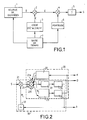
- the usual way to generate a digital spread bandwidth transmission signal, of DSSS type, consists of data to be transmitted in the form of a series D of binary elements of the same duration succeeding each other at a regular rate H d .
- This sequence D of binary elements assumed in FIG. 1, to come from a data source 1, is subjected to a first modulation carrying out the spread of spectrum, symbolized by a first multiplier 2.
- This first multiplier 2 performs the product of the binary sequence D of data with a spreading code which is another sequence C of binary elements of the same duration succeeding each other at a regular rate H c and coming from a generator 3 of spreading code.
- the cadence H c of the spreading code is much faster than that H d of the sequence of data.
- the bit rate H c of the spreading code is 20,460 times faster than that H d of the data.
- the binary signal E resulting from the first spreading modulation which is available at the output of the first multiplier 2, corresponds to the sequence C of the spreading code inverted or not at the rhythm, slow compared to its own rhythm, of the sequence D data. It is then subjected to a second modulation carrying out the formatting of transmission, symbolized by a second multiplier 4 and by a filtering device 5.
- This second transmission modulation effects the product of the spread signal E with a transmission carrier provided by a carrier generator 6, product which, once filtered by the filtering device 5, constitutes the transmitted signal S.
- the second transmission modulation can be of any type known. It is very often a single sideband modulation.
- the rates of the D data suite and the sequence C of the spreading code, as well as the carrier of the modulation of transmission are synchronized and come from a time base 7 providing the various timing signals required by the source 1, to generator 3 of spreading code and to generator 6 of carrier from a single standard clock.
- these two reverse processing operations are performed on reception, in a demodulation and despreading stage comprising, as shown in FIG. 2, a code recovery loop 20 nested in a carrier recovery loop 30.
- the signal of digital spread-band transmission S arrives at the input of this demodulation and despreading stage after having been translated into an intermediate frequency band more or less close to the base band.
- a synchronous detector 31 operating using a local carrier H L delivered by a local carrier generator 32 forming part of the carrier recovery loop 30.
- the received signal replaced in baseband is despread by a correlator 21 with a spreading code generated locally by a spreading code generator forming part of the code recovery loop 20.
- the spreading code recovery loop 20 is a loop classic with correlation window. She gets her enslavement signal from the comparison of the correlation values of the received and demodulated signal with two local versions of the spreading code offset by a constant delay, one A ahead, the other R behind a third P version of the code so-called phase spreading actually used for the despreading of the signal. It searches the time position of these versions in advance A and late R of the local spreading code leading to correlations of identical values with the signal to be despread. Its principle is based on the triangular shape of the main lobe of the code autocorrelation law binary spreading of pseudo-random type and on the absence of lobes significant side effects of this law.
- the spreading code recovery loop 20 includes three correlators in parallel, 21 A , 21, 21 R , a spreading code generator 22 providing three versions of the spreading code offset from each other by the desired delay , a comparator 23 connected at the output of the correlators 21 A and 21 R assigned to the early A and late R versions of the local spreading code and a loop filter 24 providing a servo signal to act on the rhythm of the local generator of spreading code 22 in order to make the version P of the local spreading code coincide with that of the signal to be despread.
- This spread window code recovery loop correlation which operates on the basis of an error criterion based on energy considerations is insensitive to phase errors affecting the local demodulation carrier.
- the carrier recovery loop 30 draws its servo signal from the despread signal from the operating correlator 21 p on the phase version of the local spreading code, by means of a circuit 33 for extracting a harmonic line of the carrier using for example the Costas technique.
- a loop filter 34 is inserted between the phase control of the local carrier oscillator 32 and the harmonic line extraction circuit 33.
- This power spectrum has a main lobe having a width of the order of twice the rate H c of the pseudo-random binary code. It is usual to keep part of the side lobes, which leads to assigning it a minimum frequency bandwidth slightly greater than twice the flow rate H c .
- the band allocated for the propagation of the signal is presented in two distinct parts.
- An example is the allocation to the GALILEO satellite navigation system, at the top of the L band, of two narrow frequency bands four MHz wide: E 1 (1559-1563 MHz) and E 2 (1587-1591 MHZ) on either side of the L 1 band of 24 MHz wide (1563-1587 MHz) of the GPS system.
- E 1 , E 2 when used individually, does not allow, if one wishes to respect the usual rule of a bandwidth transmitted a little more than twice the bit rate, that the use of a pseudo-random binary spreading code with a speed of the order of 2 MHz which does not allow the desired navigation precision to be achieved in civil aeronautics.
- Another example is that of code M in the future system of navigation by GPS satellites, where we look for a hole in the middle of the frequency band occupied to make room for the spreading code C / A so you can scramble it freely.
- One way to perform this replacement of a binary element by a waveform without continuous component consists in carrying out a regular division of each binary element of the pseudo-random binary code initial, this at a multiple and synchronous frequency of the code rate pseudo-random binary.
- This breakdown of the binary elements of the code initial pseudo-random causes the frequency spectrum to be split pseudo-random binary code and frequency separation of the two aftershocks obtained, over a distance corresponding to the frequency of the cutting.
- FIG. 3 gives an example of a spreading code generator diagram performing this operation.
- a generator 40 delivering a pseudo-random binary code C ps at a rate H ps low enough for its power spectrum to be within the width of one of the two authorized parts of the band which it is desired to occupy.
- This pseudo-random binary code C ps is subjected to an auxiliary modulation of type with double lateral bands without carrier, which is symbolized by a multiplier 41.
- This consists of a regular cutting of the binary elements of the pseudo-random code C ps obtained by performing the product of this pseudo-random code C ps supplied by the generator 40, by a binary carrier H m consisting of a synchronous multiple of the rate H ps of the pseudo-random binary code C ps .
- the cadence H ps of the pseudo-random binary code C ps and the modulation carrier H m are provided by the same time base 42.
- the multiplier 41 outputs a new binary code C and which is used as the code spreading in place of the initial pseudo-random binary code C ps .
- the pseudo-random binary code initial can have a bit rate of 2,046 MHZ within the bandwidth of 4 MHz allocated to each of the bands E1, E2 while the carrier of the auxiliary modulation can be a binary carrier having a frequency of 14.322 MHz corresponding to the multiple of order 7 of the bit rate of the binary code initial pseudo-random.
- FIG. 4 is a curve diagram illustrating the transformations made to the pseudo-random binary spreading code by the division of its binary elements.
- the first curve represents a segment of the pseudo-random binary code C ps formed from the binary sequence 10110, the elements of which each extend over a period 1 / H ps .
- the second curve represents the spreading code Cet resulting from a division of each binary element of the pseudo-random code C ps at a rate H m seven times greater than the flow rate H ps of this code. This division hashes each binary element of the pseudo-random code C ps into fourteen parts, which means that the resulting spreading code has a throughput fourteen times faster.
- the new spreading code obtained having a clearly debit faster allows more precise synchronization in reception with, for Consequently, at a satellite positioning receiver, a sharp increase in the accuracy of transit time measurements of signals received which ultimately translate into a marked improvement in positioning accuracy.
- This simplified despreading treatment can be used in relief from normal processing, when one of the occupied sidebands by the transmitted signal is parasitized to the point that taking it into account unhook the receiver and code recovery loops from the receiver. You just have to test the power received at the receiver in each of the sidebands occupied by the transmitted signal and eliminate a sideband and the frequency domain between the two bands lateral when the power received through this band lateral exceeds a certain threshold testifying to the presence within it of annoying parasites. So instead of having a receiver blinded and unable to function, we recover a less precise degraded operation but still very useful.
- FIG. 5 is a block diagram of the filtering stages, demodulation and despreading of a receiver having two modes of functioning, one normal and the other degraded, with an automatic allowing to switch automatically from one to the other according to the reception conditions.
- a battery of three band filters 50 is distinguished, 51, 52 put in parallel, intended to limit the band of the input signal S of three different ways.
- the input signal S is placed in a band of intermediate frequency more or less close to the baseband by upstream stages not shown of the receiver. Once filtered, it should be demodulated to be returned to baseband and despread by a stage of demodulation and despreading consisting of a recovery loop of code 20 'nested in a carrier recovery loop 30' according to the same principle as that shown in figure 2.
- the three band filters 50, 51, 52 propose three possible versions, one of which is chosen to be applied to the entrance to the demodulation and despreading stage.
- the input signal S assumed to be spread in frequency using a binary spreading code obtained by cutting out the binary elements of a pseudo-random binary code, has a spectrum with double lateral bands B 1 , B 2 and occupies a frequency domain bounded by its two lateral bands B 1 , B 2 .
- the first band filter 50 retains only the lower side band B 1 of the input signal S.
- the second band filter 51 preserves the entire frequency domain bounded by the two side bands B 1 , B 2 of the signal d input S.
- the third band filter 52 retains only the upper side band B 2 of the input signal S.
- the output signals of the three band filters 50, 51, 52 are applied to the inputs of an interposed selector 53 in front of the demodulation and despreading stage. Those of the two side band filters 50, 52 are also applied to individual power detectors 54, 55.
- the outputs of the power detectors 54, 55 are connected to a parasite detector 56 which controls the selector 53 as well as the type of despreading code used by the local code generator 22 'of the loop 20 'code recovery from the demodulation and despreading stage, and the frequency of adjustment of the local generator 32 'of the loop carrier recovery 30 'from the demodulation and despreading stage.
- the parasite detector 56 compares the signal powers received in the two lateral bands B 1 and B 2 with a threshold.
- the selector If the threshold is not reached, it commands the selector to choose the output signal of the band filter 51 and gives instructions to the local code generator 22 'to generate replicas of the binary double band spreading code. side frequencies actually used, and the local carrier generator 32 ′ to adopt, as basic setting frequency, the central frequency of the band delimited in the input signal S by the two side bands B 1 and B 2 .
- the parasite detector switches off this side strip by commanding the selector 53 to choose the output signal of the band filter 50 or 52 centered on the other side strip. Simultaneously, it instructs the local code generator 22 ′ to generate replicas of the pseudo-random binary code underlying the spreading code actually used, and the local carrier generator 32 ′ to adopt, as frequency of basic setting, the center frequency of the sideband kept.
- the block diagram of Figure 5 uses, to facilitate the understanding, an assembly of boxes performing different functions.
- the received signal is digitized at intermediate frequency, before its band limitation filtering, its detection by the demodulator synchronous and its correlation despreading which are achieved by digital processing using one or more signal processors controlled by software, performing different tasks corresponding to different functions mentioned, in parallel or in timeshare, according to a order adapted to the digital techniques used.
Landscapes
- Engineering & Computer Science (AREA)
- Radar, Positioning & Navigation (AREA)
- Remote Sensing (AREA)
- Computer Networks & Wireless Communication (AREA)
- Physics & Mathematics (AREA)
- General Physics & Mathematics (AREA)
- Signal Processing (AREA)
- Position Fixing By Use Of Radio Waves (AREA)
- Synchronisation In Digital Transmission Systems (AREA)
Abstract
Description
- une figure 1 est un schéma de principe d'un émetteur engendrant un signal de transmission de données à bande étalée selon la méthode DSSS,
- une figure 2 est un schéma de principe d'un étage de démodulation et de désétalement utilisable en réception d'un signal de transmission numérique à bande étalée selon la méthode DSSS,
- une figure 3 est un schéma de principe d'un générateur de code d'étalement à spectre de fréquence dédoublé avec un trou médian dans la bande de fréquence occupée,
- une figure 4 est un diagramme de courbes représentant une portion de code d'étalement binaire pseudo-aléatoire et une portion de code d'étalement à spectre de fréquence dédoublé obtenue par découpage des éléments binaire de la portion de code binaire pseudo-aléatoire, et
- une figure 5 est un schéma de principe des étages de filtrage, de démodulation et de désétalement d'un récepteur ayant deux modes de fonctionnement, un normal et l'autre dégradé, le mode de fonctionnement dégradé effectuant un traitement du signal reçu conforme à l'invention.
- la suite des données D provenant du corrélateur 21,
- le signal d'asservissement K provenant du comparateur 23 par l'intermédiaire du filtre de boucle 24 et agissant sur le rythme du générateur local 22 de code d'étalement. Ce signal B fournit une mesure du retard en réception du code d'étalement du signal traité par rapport à la version de code d'étalement utilisée à l'émission dont la phase est déduite de la connaissance de l'horloge étalon utilisée à l'émission, qui est une information fournie par les données transmises, et donne une indication du temps mis par le signal pour franchir la distance satellite-récepteur, et
- le signal d'asservissement A provenant du circuit d'extraction de raie 33 par l'intermédiaire du filtre de boucle 34, qui fournit une mesure de l'effet doppler affectant en réception la porteuse de transmission.
Tc la période d'un élément binaire, et
ω la pulsation : ω = 2πf.
Ce spectre de puissance a un lobe principal ayant une largeur de l'ordre du double du débit Hc du code binaire pseudo-aléatoire. Il est habituel de conserver une partie des lobes latéraux, ce qui conduit à lui attribuer une largeur minimale de bande de fréquence légèrement supérieure au double du débit Hc. Lorsqu'il est modulé par une suite de données de débit Hd inférieur et synchrone, le spectre de puissance d'un code binaire pseudo-aléatoire ne subit pas de modification, de sorte que le signal de données à bande étalée résultant continue d'occuper la même bande de fréquence que le code d'étalement binaire pseudo-aléatoire ayant servi à l'étaler. La modulation de transmission, lorsqu'elle est de type à bande latérale unique ne fait que translater ce spectre dans une bande de fréquence affectée à la propagation des signaux.
Claims (4)
- Procédé de traitement d'un signal de transmission numérique à bande étalée obtenue au moyen d'un code d'étalement dit "résultant" provenant d'un découpage des éléments binaires d'un code binaire pseudo-aléatoire dit "initial", à une fréquence multiple et synchrone du débit du code binaire pseudo-aléatoire initial, ledit signal de transmission en bande étalée présentant, par suite du code d'étalement résultant utilisé, un spectre de fréquence dédoublé occupant deux bandes latérales (B1, B2) situées aux extrémités d'un domaine de fréquence dont la largeur dépend de la fréquence du découpage, ce procédé de traitement étant caractérisé en ce qu'il consiste à ne considérer, dans le signal de transmission numérique reçu, que l'une (B1) ou l'autre (B2) de ses bandes latérales, et à désétaler le signal partiel correspondant à la bande latérale considérée (B1 ou B2) au moyen du code binaire pseudo-aléatoire initial à l'origine du code d'étalement résultant effectivement utilisé.
- Procédé de traitement d'un signal de transmission numérique à bande étalée obtenue au moyen d'un code d'étalement dit "résultant" provenant d'un découpage des éléments binaires d'un code binaire pseudo-aléatoire dit "initial", à une fréquence multiple et synchrone du débit du code binaire pseudo-aléatoire initial, ledit signal de transmission en bande étalée présentant, par suite du code d'étalement résultant utilisé, un spectre de fréquence dédoublé occupant deux bandes latérales (B1, B2) situées aux extrémités d'un domaine de fréquence dont la largeur dépend de la fréquence du découpage, ce procédé de traitement étant caractérisé en ce qu'il consiste à :mesurer les puissances reçues dans chacune des deux bandes latérales (B1, B2) occupées par le signal de transmission numérique,comparer les deux mesures de puissances obtenues avec au moins un seuil de puissance admissible, eten fonction du résultat de ces comparaisons :soit, si les mesures des puissances reçues dans les bandes latérales (B1, B2) restent inférieures au seuil de puissance admissible, considérer la bande spectrale complète du signal de transmission numérique constituée des deux bandes latérales (B1, B2) et du domaine de fréquence qui les sépare et désétaler le signal reçu occupant la bande spectrale complète au moyen du code d'étalement résultant,soit, si une mesure de la puissance reçue dans une bande latérale (B1 ou B2) dépasse le seuil de puissance admissible, écarter la bande latérale concernée (B1 ou B2), ne considérer, dans le signal de transmission numérique reçu, que l'autre bande latérale (B2 ou B1), et désétaler le signal partiel correspondant à la bande latérale considérée (B2 ou B1) au moyen du code binaire pseudo-aléatoire initial à l'origine du code d'étalement résultant effectivement utilisé.
- Dispositif de traitement en réception, d'un signal de transmission numérique à bande étalée obtenue au moyen d'un code d'étalement dit "résultant" provenant d'un découpage des éléments binaires d'un code binaire pseudo-aléatoire dit "initial", à une fréquence multiple et synchrone du débit du code binaire pseudo-aléatoire initial, ledit signal de transmission en bande étalée présentant, par suite du code d'étalement résultant utilisé, un spectre de fréquence dédoublé occupant deux bandes latérales (B1, B2) situées aux extrémités d'un domaine de fréquence dont la largeur dépend de la fréquence du découpage, ce dispositif étant caractérisé en ce qu'il comporte :des moyens de filtrage (50, 51, 52) permettant d'isoler la bande spectrale complète du signal de transmission numérique constituée des deux bandes latérales (B1, B2) et du domaine de fréquence qui les sépare, et chacune des bandes latérales (B1, B2),des moyens de démodulation et de désétalement (20', 30') équipés d'un générateur de porteuse locale (32') pouvant prendre pour fréquence de réglage de base, la fréquence centrale de la bande spectrale complète occupée par le signal de transmission numérique où l'une des fréquences centrales de ses bandes latérales (B1, B2), et d'un générateur local de code (22') pouvant engendrer des répliques du code d'étalement résultant ou du code binaire pseudo-aléatoire initial,un sélecteur (53) intercalé entre les moyens de filtrage (50, 51, 52) et les moyens de démodulation et de désétalement (20', 30'), permettant d'appliquer aux moyens de démodulation et de désétalement (20', 30') le signal reçu dans la bande spectrale complète occupée par le signal de transmission numérique ou l'un des signaux reçus dans les bandes latérales (B1, B2) du signal de transmission numérique,des moyens (54, 55) de mesure des puissances reçues dans les deux bandes latérales (B1, B2) du signal de transmission numérique opérant à la suite des moyens de filtrage (50, 51, 52),des moyens (56) de détection de parasites recevant les mesures provenant des moyens de mesure de puissance (54, 55), les comparant à un seuil et utilisant les résultats de ces comparaisons pour commander le sélecteur (53) et fournir une consigne de fréquence de réglage de base pour le générateur de porteuse locale (32') et une consigne de code pour le générateur local de code (22').
- Dispositif selon la revendication 3, caractérisé en ce que les moyens (56) de détection de parasite renferment une logique qui :lorsque les mesures fournies par les moyens (54, 55) de mesures des puissances reçues restent inférieures au seuil, donne pour consigne au sélecteur (53), de choisir le signal issu des moyens de filtrage (51) correspondant à la bande spectrale complète du signal de transmission numérique, pour consigne au générateur (32') de porteuse locale, d'adopter pour fréquence de réglage de base la fréquence centrale de la bande spectrale complète du signal de transmission numérique et pour consigne au générateur local (22') de code, d'engendrer des répliques du code d'étalement résultant, etlorsque l'une des mesures fournies par les moyens (54, 55) de mesures des puissances reçues franchit le seuil, donne pour consigne au sélecteur (53), de choisir le signal issu des moyens de filtrage (50 ou 52) correspondant à la bande latérale (B1 ou B2) qui n'est pas concernée par le franchissement du seuil, pour consigne au générateur (32') de porteuse locale, d'adopter pour fréquence de réglage de base la fréquence centrale de cette bande latérale non concernée (B1 ou B2), et pour consigne au générateur local (22') de code, d'engendrer des répliques du code binaire pseudo-aléatoire initial.
Applications Claiming Priority (2)
| Application Number | Priority Date | Filing Date | Title |
|---|---|---|---|
| FR0016877A FR2818834B1 (fr) | 2000-12-22 | 2000-12-22 | Procedes et dispositif de traitement en reception d'un signal de transmission numerique a bande etalee |
| FR0016877 | 2000-12-22 |
Publications (2)
| Publication Number | Publication Date |
|---|---|
| EP1229665A1 true EP1229665A1 (fr) | 2002-08-07 |
| EP1229665B1 EP1229665B1 (fr) | 2007-10-31 |
Family
ID=8858085
Family Applications (1)
| Application Number | Title | Priority Date | Filing Date |
|---|---|---|---|
| EP20010403201 Expired - Lifetime EP1229665B1 (fr) | 2000-12-22 | 2001-12-11 | Procédé et dispositif de traitement en réception d'un signal numérique à bande étalée |
Country Status (4)
| Country | Link |
|---|---|
| EP (1) | EP1229665B1 (fr) |
| CA (1) | CA2364867C (fr) |
| DE (1) | DE60131132D1 (fr) |
| FR (1) | FR2818834B1 (fr) |
Citations (1)
| Publication number | Priority date | Publication date | Assignee | Title |
|---|---|---|---|---|
| US6148022A (en) * | 1998-01-28 | 2000-11-14 | The Aerospace Corporation | NRZ and biphase-L formatted quadriphase modulated GPS transmission method |
-
2000
- 2000-12-22 FR FR0016877A patent/FR2818834B1/fr not_active Expired - Fee Related
-
2001
- 2001-12-11 EP EP20010403201 patent/EP1229665B1/fr not_active Expired - Lifetime
- 2001-12-11 DE DE60131132T patent/DE60131132D1/de not_active Expired - Lifetime
- 2001-12-20 CA CA 2364867 patent/CA2364867C/fr not_active Expired - Fee Related
Patent Citations (1)
| Publication number | Priority date | Publication date | Assignee | Title |
|---|---|---|---|---|
| US6148022A (en) * | 1998-01-28 | 2000-11-14 | The Aerospace Corporation | NRZ and biphase-L formatted quadriphase modulated GPS transmission method |
Also Published As
| Publication number | Publication date |
|---|---|
| EP1229665B1 (fr) | 2007-10-31 |
| CA2364867A1 (fr) | 2002-06-22 |
| CA2364867C (fr) | 2010-08-10 |
| FR2818834A1 (fr) | 2002-06-28 |
| FR2818834B1 (fr) | 2006-07-14 |
| DE60131132D1 (de) | 2007-12-13 |
Similar Documents
| Publication | Publication Date | Title |
|---|---|---|
| EP3709058B1 (fr) | Procédé de contrôle d'intégrité d'un signal de radionavigation par satellite et recepteur apte à implementer ce procédé. | |
| CA2412136A1 (fr) | Procede et dispositif de calcul de la fonction discriminante de signaux modules avec une ou plusieurs sous-porteuse | |
| EP2520949A1 (fr) | Dispositif de réception d'un système de positionnement par satellite comprenant une fonction de détection de faux accrochages | |
| EP2095150B1 (fr) | Procédé et dispositif de réception d'un signal de radionavigation à modulation boc | |
| EP2588884B1 (fr) | Procédé de réduction de l'éblouissement d'un récepteur recevant des signaux depuis des émetteurs | |
| CA2312030A1 (fr) | Procede et dispositif de traitement en reception d'un signal l2 de satellite gps | |
| WO2005006012A1 (fr) | Procede et dispositif de demodulation de signaux de radionavigation par satellite. | |
| CA2459369A1 (fr) | Procede et dispositif d'antiparasitage, en reception, d'un signal radioelectrique a large bande | |
| EP0917299B1 (fr) | Transmission numérique à étalement de spectre par séquence directe avec génération d'un signal d'interférences | |
| WO2002033437A1 (fr) | Systeme de suivi d"un mobile | |
| EP1436641B1 (fr) | Procede et dispositif de poursuite d'un signal de transpondeur en presence d'une modulation de frequence parasite du pilote de transposition | |
| EP0924531A1 (fr) | Signal processing method of a positioning system using satellites | |
| EP1229665B1 (fr) | Procédé et dispositif de traitement en réception d'un signal numérique à bande étalée | |
| FR2770060A1 (fr) | Recepteur differentiel a etalement de spectre par sequence directe avec moyens mixtes de formation d'un signal d'interferences | |
| FR2962228A1 (fr) | Procede de reduction de l'eblouissement d'un recepteur au sein d'un systeme, notamment de geolocalisation. | |
| EP3779515B1 (fr) | Procédé de détection d'une fausse synchronisation d'un récepteur avec un satellite, récepteur et produit programme d'ordinateur associés | |
| EP1508816B1 (fr) | Procédé de validation de la détection d'un pic de corrélation par un récepteur de système de positionnement par satellite | |
| CA3260894A1 (fr) | Method for detecting an interfering signal in a gnss receiver and associated detection device | |
| EP0737868A1 (fr) | Boucle à verrouillage de délai pour utilisation dans un récepteur de signaux GPS | |
| CA2957634A1 (fr) | Procede de detection d'une fausse synchronisation d'un recepteur avec un satellite, recepteur et produit programme d'ordinateur associes | |
| EP1252722B1 (fr) | Procede de radiocommunications amrc avec codes d'acces et recepteur correspondant | |
| EP2724179B1 (fr) | Optimisation d'un systeme de localisation comprenant des stations de base emettrices terrestres | |
| EP0921409A1 (fr) | Récepteur GPS bi-fréquence, opératoire sur toutes les mesures en présence d'encryptage | |
| EP0531203B1 (fr) | Procédé et dispositif pour la transmission d'information et la localisation de mobiles | |
| FR2811834A1 (fr) | Systeme differentiel de navigation par satellites avec liaison cryptee de donnees |
Legal Events
| Date | Code | Title | Description |
|---|---|---|---|
| PUAI | Public reference made under article 153(3) epc to a published international application that has entered the european phase |
Free format text: ORIGINAL CODE: 0009012 |
|
| AK | Designated contracting states |
Kind code of ref document: A1 Designated state(s): AT BE CH CY DE DK ES FI FR GB GR IE IT LI LU MC NL PT SE TR |
|
| AX | Request for extension of the european patent |
Free format text: AL;LT;LV;MK;RO;SI |
|
| 17P | Request for examination filed |
Effective date: 20020925 |
|
| AKX | Designation fees paid |
Designated state(s): BE DE FR GB IT |
|
| 17Q | First examination report despatched |
Effective date: 20060831 |
|
| GRAP | Despatch of communication of intention to grant a patent |
Free format text: ORIGINAL CODE: EPIDOSNIGR1 |
|
| GRAS | Grant fee paid |
Free format text: ORIGINAL CODE: EPIDOSNIGR3 |
|
| GRAA | (expected) grant |
Free format text: ORIGINAL CODE: 0009210 |
|
| AK | Designated contracting states |
Kind code of ref document: B1 Designated state(s): BE DE FR GB IT |
|
| REG | Reference to a national code |
Ref country code: GB Ref legal event code: FG4D Free format text: NOT ENGLISH |
|
| REF | Corresponds to: |
Ref document number: 60131132 Country of ref document: DE Date of ref document: 20071213 Kind code of ref document: P |
|
| PGFP | Annual fee paid to national office [announced via postgrant information from national office to epo] |
Ref country code: GB Payment date: 20071205 Year of fee payment: 7 |
|
| GBV | Gb: ep patent (uk) treated as always having been void in accordance with gb section 77(7)/1977 [no translation filed] | ||
| PGFP | Annual fee paid to national office [announced via postgrant information from national office to epo] |
Ref country code: DE Payment date: 20071206 Year of fee payment: 7 |
|
| PLBE | No opposition filed within time limit |
Free format text: ORIGINAL CODE: 0009261 |
|
| STAA | Information on the status of an ep patent application or granted ep patent |
Free format text: STATUS: NO OPPOSITION FILED WITHIN TIME LIMIT |
|
| 26N | No opposition filed |
Effective date: 20080801 |
|
| PG25 | Lapsed in a contracting state [announced via postgrant information from national office to epo] |
Ref country code: DE Free format text: LAPSE BECAUSE OF FAILURE TO SUBMIT A TRANSLATION OF THE DESCRIPTION OR TO PAY THE FEE WITHIN THE PRESCRIBED TIME-LIMIT Effective date: 20080201 |
|
| PG25 | Lapsed in a contracting state [announced via postgrant information from national office to epo] |
Ref country code: GB Free format text: LAPSE BECAUSE OF FAILURE TO SUBMIT A TRANSLATION OF THE DESCRIPTION OR TO PAY THE FEE WITHIN THE PRESCRIBED TIME-LIMIT Effective date: 20071031 |
|
| PG25 | Lapsed in a contracting state [announced via postgrant information from national office to epo] |
Ref country code: IT Free format text: LAPSE BECAUSE OF NON-PAYMENT OF DUE FEES Effective date: 20071231 |
|
| REG | Reference to a national code |
Ref country code: FR Ref legal event code: PLFP Year of fee payment: 15 |
|
| REG | Reference to a national code |
Ref country code: FR Ref legal event code: PLFP Year of fee payment: 16 |
|
| REG | Reference to a national code |
Ref country code: FR Ref legal event code: PLFP Year of fee payment: 17 |
|
| PGFP | Annual fee paid to national office [announced via postgrant information from national office to epo] |
Ref country code: BE Payment date: 20171124 Year of fee payment: 17 |
|
| REG | Reference to a national code |
Ref country code: BE Ref legal event code: MM Effective date: 20181231 |
|
| PG25 | Lapsed in a contracting state [announced via postgrant information from national office to epo] |
Ref country code: BE Free format text: LAPSE BECAUSE OF NON-PAYMENT OF DUE FEES Effective date: 20181231 |
|
| PGFP | Annual fee paid to national office [announced via postgrant information from national office to epo] |
Ref country code: FR Payment date: 20201125 Year of fee payment: 20 |
|
| P01 | Opt-out of the competence of the unified patent court (upc) registered |
Effective date: 20230427 |