The invention relates to a method for extracting device status information of a
device, and to necessary means for performing said method.
Electronic consumer devices are often repaired by service workshops which are
servicing a broad variety of devices developed by different manufacturers. In
order to facilitate the repairing process, the manufaturers usually integrate a
diagnostic software into their electronic devices, in particular in high complexity
devices. This diagnostic software can be used for fault finding, preferably
together with an external diagnostic apparatus which controls the diagnostic
software.
Document US 5,916,287 for example discloses a modular automotive test and
information system. In particular, an integrated control module is described to
which at least one instrumentation module is connected via an IEEE1394 bus.
Every instrumentation module is adapted to run diagnostic applications for a
particular vehicle component.
Further, document EP 0 939 321 A1 describes a high speed serial test and
measurement equipment interface and system using the same wherein a computer
is used to control electronic test equipment. The computer acts as a controller
to manage configuration and operation of the various test and measurement
equipment.
However, as each different device type usually requires a different diagnostic
apparatus, respectively, and as different device types usually are accessable
via different communication/control protocols only, it is necessary to use a
broad variety of different diagnostic apparatus or different control protocols,
which in addition often requires the use of different interfaces connecting the
device with the corrresponding diagnostic apparatus, respectively. The situation
even complicates more if the devices are diagnosed via a network. This results
in a costly and complex diagnostic equipment.
It is an object of the present invention to provide a method and necessary
means to perform it which make it possible to facilitate the diagnostic process,
in particular with respect to devices being connected to each other via an
IEEE 1394 network.
To solve this object, the present invention provides a method for extracting
device status information of a device which is connected to an IEEE 1394 interface,
which is characterized by a) reading out device specific information from
said device, and/or b) instructing said device to execute device self tests and
reading out corresponding self test results from said device, wherein steps a)
and b) are performed on the basis of a low level communication protocol of said
IEEE 1394 interface.
The present invention further provides a device status information tester for extracting
device status information of a device which supports IEEE1394 and is
connectable to said device status information tester, which is charaterized by an
IEEE1394 interface, wherein said device status information tester provides
functionality for communicating with said device via said IEEE1394 interface by
using a low level communication protocol of said IEEE1394 interface.
Further, the present invention provides a device which is controllable by a device
status information tester which supports IEEE1394, which is charaterized
by an IEEE1394 interface, a storage means accessable for said device status
information tester, a means for exectuing self tests and for providing said storage
means with a result of said self tests, wherein a communication between
said commanding device and said receiving means via said IEEE1394 interface
is based upon a low level communication protocol of said IEEE1394 interface.
Last, the present invention provides a service diagnostic system, comprising a
device status information tester according to anyone of the claims 6 to 8, a device
according to anyone of the claims 9 to 16, and an IEEE1394 bus as a
connection between said device and said device status information tester,
wherein said device and said device status information tester communicate via
said low level communication protocol over said respective IEEE1394 interfaces
and said IEEE1394 bus.
Preferred embodiments of this method, device, device service information tester
and service diagnostic system which are defined in independent claims 1, 6, 9
and 17, respectively, are respectively defined in the respective following dependent
claims.
The service diagnostic system provided by the invention comprises a service diagnostic
interface (in the following referred to as SDI) which is based upon the
IEEE1212-2000/IEEE1394-1995 standard (in the following only referred to as
IEEE1394 standard). As this standard is used in many devices, a broad variety
of different device hardware may be used as a basis for the SDI. If a device
should not directly support the IEEE1394 standard, it is possible in most cases
to add an IEEE1394 interface to the device, thus making it compatible to the
IEEE1394 standard, and therfore suitable as a basis for the SDI.
An important aspect of the present invention is that the principles of a SDI communication
mechanism for communicating between the device and the device
status information tester of the service diagnostic system are based upon existing
communication mechanisms that are common to all different IEEE1394
communication/control protocol mechanisms used by different IEEE1394 supporting
devices. This is achieved by using a low level communication protocol
underlying all "real" communication/control protocols supported by the different
IEEE1394 devices. Preferably, the low level communication protocol is based
upon the Quadlet read/write protocol, which forms a basis of the IEEE1394
standard. The Quadlet read/write protocol allows four byte rate reading and
writing.
An advantage thereof is that the SDI communication mechanism can be implemented
at low cost, as it is only necessary to introduce a minimum of new functionality
for directly using the low level communication protocol. Further, the
SDI communication mechanism is independent of any "higher" communication/control
protocol applied over IEEE1394 (for example AV/C (audio, video / control)),
thus making it applicable to any device which comprises an IEEE1394 interface.
IEEE1394 interfaces may be a part of SDI software and/or SDI hardware, which
is preferaby located in both the device status information tester and the device.
The SDI further comprises a connection between the device and the device
status information tester, for example an IEEE1394 serial bus. Further, the SDI
software/hardware of the device status information tester and the device may
comprise additional software to control the respective IEEE1394 interfaces.
The device status information tester preferably is a computing device, for example
a PC (Personal Computer), but is not restricted thereto. Every hardware or
software which provides the functionality needed to extract device status information
can be regarded as device status information tester (in the following only
referred to as tester).
If several devices to be controlled by the tester are connected via an IEEE1394
network, then at least some of the devices may comprise two or more IEEE1394
interfaces, respectively. In this case, the device status information tester may
also comprise two or more IEEE1394 interfaces, depending on the structure of
the network connecting the different devices and the device status information
tester with each other, respectively. Thus, in such a case, the corresponding SDI
comprises more than two IEEE1394 interfaces.
The SDI software of the tester and the device may be divided into SDI common
software and SDI specific software, respectively. That is, the SDI specific software
acts like an adaption layer to "connect" the SDI specific software, which
is device dependent, to the SDI common software which is device independent.
The advantage thereof is that in case of a new device supporting SDI only the
SDI specific software has to be adapted, the SDI common software remains untouched.
The SDI software/hardware, preferably the SDI common software of the tester
provides at least a part of the following functionality:
The device specific information for example comprises a name of the manufacturer
of the device, a device model number and a textual description of the device.
The device specific information is preferably not changeable by the tester.
This is achieved for example by keeping it in a ROM (read only memory) storage.
By reading out all accessable device specific information of all connected
devices, the tester is capable of generating a list of all connected devices.
In the following description, the sum of self test result information and device
specific information will be referred to as device status information.
The SDI software/hardware, preferably the SDI common software/hardware of
the device provides at least a part of the following functionality:
To instruct the device, for example to instruct the device to start the buit-in
self test software, the tester writes command information into the storage
means, preferably into command register within the storage means, which is
then interpreted by the device. To provide the tester with device status information
(for example test results), the device writes the device status information
into the storage means, preferably into status register within the storage
means. The tester reads the device status information out of the storage
means, and processes it. The tester may for example check at regular time intervals
if the content of the storage means has changed, and exclusively read
out status information that has changed.
The communication/controlling process decribed above is preferably executed
by using the low level communication protocol exclusively.
To instruct the tester and to display extracted device status information, the
tester preferably comprises a user interface. Via the user interface, the user
may for example first start a general diagnostic software stored within the
tester which identifies accessable devices in the network by extracting device
specific information, respectively. All identified devices may be sorted and displayed
to the user. To test the identified devices, the user may start for each
device to be tested an individual testing software which manages the start of
the respective buit-in self test software and the extraction of the test results.
The steps described above may also be executed automatically by the tester itself.
The device may comprise both an IEEE1394 interface and a remote connection
capability. In this case, the device can be diagnosed by a remote tester via a
remote connection, for example the internet or the telephone.
Further features and advantages of a preferred embodiment according to the
present invention will be explained below in conjunction with the accompanying
drawings, in which
- Fig.1
- shows a schematic drawing of a data format used to store device status
information and other information being relevant to the SDI according
to the present invention,
- Fig.2
- shows a list of root directory entries being relevant for the SDI according
to the present invention;
- Fig.3
- shows a list of instance directory entries being relevant for the SDI according
to the present invention;
- Fig.4
- shows a list of a specifying organization unit directory entries being
relevant for the SDI according to the present invention;
- Fig.5
- shows a schematic drawing of a data format of a Version entry in the
specifying organization unit directory according to the present invention;
- Fig.6
- shows a schematic drawing of a data format of a Response_Reg_Offset
entry in the specifying organization unit directory according to the
present invention;
- Fig.7
- shows a schematic drawing of a data format of a Test_Start_Offset entry
in the specifying organization unit directory according to the present
invention;
- Fig.8
- shows a schematic drawing of a data format of a status register
Response_Register according to the present invention;
- Fig.9
- shows a schematic drawing of a data format of a command register
Test_Start_Register according to the present invention;
In the following description, making reference to figures 1 to 9, a preferred embodiment
of a storage means of a device supporting SDI is exemplary described.
In figures 2, 3 and 4, "M" means "mandatory", and "O" means "optional",
wherein the columns "SDI" refers to the service diagnostic interface according
to the present invention, and the columns "1212r" to the known IEEE1212-2000
standard already referred to.
As the SDI is based upon the IEEE1212-2000 standard, SDI relevant information
information has to be stored within the device according to the IEEE1212-2000
specification. That is, SDI relevant information is stored in a storage
means using a first data-structure 1 which comprises a preferably two-bit type
field 2, a preferably six-bit Key_ID field 3 and a preferably 24-bit Data field 4.
The type field 2 describes whether information of the Data field 4 represents
"immediate" information or offset information (to a location in a memory, to a
leaf or a directory). The Key_ID field 3 specifies the type of the information (e.g.
"Vendor_ID") which is contained in the Data field 4 .
The storage means preferably comprises a directory hirarchy. Parts of that directory
hirarchy are already existing in the IEEE1212 standard. The invention
uses this directory hirarchy, which comprises a
root directory 5 providing the
following root directory entries of the first data-
structure 1 as SDI relevant information,
as shown in figure 2:
The root directory 5 may further comprise optional entries for model icons 16,
for example, and/or additional mandatory entries 17 containing information
about node capabilities, for example.
The combination of information of the Model_ID entry 9 and of the Vendor_ID
entry 6 is normally sufficient to identify a corresponding diagnostic/test software
to be used by a tester to diagnose the device. However, the HW_Version
entry 15 may optionally specify this diagnostic/test software.
If only one language is used within the strings to which the Text_Descriptor entries
7, 10 are pointing to, then the text contained in the strings preferably
uses a Minimal one-byte ASCII character set. The text can be specified by an
offset, a leaf or a leaf directory. The tester must read the Minimal one-byte ASCII
string. If more than one language is used, then the Text_Descriptor entries
7, 10 should point to a leaf directory which contains the text, with the Minimal
one-byte ASCII string as the first entry. The tester does only have to read the
Minimal one-byte ASCII string.
The directory hirarchy of the storage means comprises the instance directory
14 as a subdirectory of the root direcory 5, as shown in figure 3. The instance
directory 14 generally comprises pointer entries to unit directories of the device.
There must be generally at least one unit directory in each devive corresponding
to the control protocol used by the device. This is indicated in the instance
directory 14 by the entries 19 and 20. According to the present invention,
the instance directory 14 comprises an additional SO_Unit_Directory entry
18 which points to a specifying organization unit directory 12 containing at
least parts of device specific functionality and parts of common functionality
needed to specify the SDI, i. e. needed to communicate using the low level communication
protocol. The exact values of the entries of the specifying organization
unit directory 12 can be determined by a specifying organization on their
own, so there is the freedom that each specifying organization/company
chooses its own specific entry values, which do not affect the core of the
present invention.
In the following, entries of the
unit directory 12 will be explained, as shown in
figure 4. The specifying
organization unit directory 12 as a subdirectory of the
instance directory 14 comprises:
The status register Response_Register is used to provide device status information
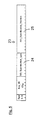
to be read out by the tester. The third data-structure 27 of this The
Response_Register is shown in figure 8. It comprises a 31-bit response field 33
and a Busy_Flag field 34, which can show the values "0" or "1".
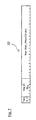
The command register Test_Start_Register is represented by a data structure
31 comprising a Test_Command field 35 which can be filled by the tester with
command information. The Test_Start_Register 31 further comprises an
INI_Flag field 36 which can show the values "0" or "1", as shown in figure 9.
The device executes the following steps when a command in form of command
information including an INI_Flag set to a the value "1" is written by the tester
into the command register Test_Start_Register of said device:
- The execution of said command is started, thereby
- the Busy_Flag in said Busy_Flag field 34 of the status register
Response_Register is set to the value "1",
- and the INI_Flag is set to the value "0".
- A corresponding self test result as device status information is written
into the 31-bit response field 33 of the status register Response_Register after
having completed the command,
- the Busy_Flag is set to the value "0", wherein
- the self test result is read out of the 31-bit response field 33 of the status
register Response_Register 27 by the tester after the INI_Flag has been set from
the value "1" to the value "0" by the device,
- and the read out self test result is interpreted according to an actual
value of said Busy_Flag. That is, when the tester sees the "1" to "0" transition of
the Busy_Flag the content of the remaining 31 bits of the read out self test result
is complete and can be interpreted therefore.
Preferably, the tester immediately starts to read out the self test result of the response
field 33 of the status register Response_Register 27 after the INI_Flag
has been set from the value "1" to the value "0" by the device, and keeps then
"poll-reading" the self test result of the response field 33 and the Busy_Flag
field 34 of the status register Response_Register 27, i. e. the tester reads at
several times, each time prooving if the "1" to "0" transition of the Busy_Flag-has
already happened. If the transition has happened, then the tester knows
that the read out self test result of the response field 33 is complete. This
mechanism is required as the execution of the command by the device usually
takes a few seconds, and the tester can only find out if the command is already
completed by permanently prooving the Busy_Flag, which means by permanently
reading out the whole status register Response_Register 27.
All reading/writing procedures by the tester are preferably performed by using
the asynchronous Quadlet read/write protocol.
All offsets preferably point to a CSR (control and status register) memory.