EP1229300A1 - Sliding caliper and grip - Google Patents
Sliding caliper and grip Download PDFInfo
- Publication number
- EP1229300A1 EP1229300A1 EP02250052A EP02250052A EP1229300A1 EP 1229300 A1 EP1229300 A1 EP 1229300A1 EP 02250052 A EP02250052 A EP 02250052A EP 02250052 A EP02250052 A EP 02250052A EP 1229300 A1 EP1229300 A1 EP 1229300A1
- Authority
- EP
- European Patent Office
- Prior art keywords
- grip
- main scale
- caliper
- holding
- component
- Prior art date
- Legal status (The legal status is an assumption and is not a legal conclusion. Google has not performed a legal analysis and makes no representation as to the accuracy of the status listed.)
- Granted
Links
- 238000005259 measurement Methods 0.000 description 20
- 210000003813 thumb Anatomy 0.000 description 10
- 210000003811 finger Anatomy 0.000 description 8
- 239000000463 material Substances 0.000 description 5
- 239000004033 plastic Substances 0.000 description 5
- 229920003023 plastic Polymers 0.000 description 5
- 238000012545 processing Methods 0.000 description 5
- 210000000078 claw Anatomy 0.000 description 4
- 238000004519 manufacturing process Methods 0.000 description 4
- 239000003921 oil Substances 0.000 description 4
- 229920003002 synthetic resin Polymers 0.000 description 3
- 239000000057 synthetic resin Substances 0.000 description 3
- XAGFODPZIPBFFR-UHFFFAOYSA-N aluminium Chemical compound [Al] XAGFODPZIPBFFR-UHFFFAOYSA-N 0.000 description 2
- 229910052782 aluminium Inorganic materials 0.000 description 2
- 238000009413 insulation Methods 0.000 description 2
- 239000007787 solid Substances 0.000 description 2
- 239000002023 wood Substances 0.000 description 2
- 229910000831 Steel Inorganic materials 0.000 description 1
- 238000005299 abrasion Methods 0.000 description 1
- 238000011109 contamination Methods 0.000 description 1
- 239000010730 cutting oil Substances 0.000 description 1
- 238000013461 design Methods 0.000 description 1
- 230000006866 deterioration Effects 0.000 description 1
- 230000005489 elastic deformation Effects 0.000 description 1
- 239000000835 fiber Substances 0.000 description 1
- 230000005484 gravity Effects 0.000 description 1
- 238000012423 maintenance Methods 0.000 description 1
- 238000012986 modification Methods 0.000 description 1
- 230000004048 modification Effects 0.000 description 1
- 230000000717 retained effect Effects 0.000 description 1
- 239000010959 steel Substances 0.000 description 1
- 239000000126 substance Substances 0.000 description 1
Images




Classifications
-
- G—PHYSICS
- G01—MEASURING; TESTING
- G01B—MEASURING LENGTH, THICKNESS OR SIMILAR LINEAR DIMENSIONS; MEASURING ANGLES; MEASURING AREAS; MEASURING IRREGULARITIES OF SURFACES OR CONTOURS
- G01B3/00—Measuring instruments characterised by the use of mechanical techniques
- G01B3/20—Slide gauges
-
- G—PHYSICS
- G01—MEASURING; TESTING
- G01B—MEASURING LENGTH, THICKNESS OR SIMILAR LINEAR DIMENSIONS; MEASURING ANGLES; MEASURING AREAS; MEASURING IRREGULARITIES OF SURFACES OR CONTOURS
- G01B3/00—Measuring instruments characterised by the use of mechanical techniques
- G01B3/002—Details
Definitions
- the present invention relates to a caliper and a caliper grip. More specifically, it relates to a caliper having a grip movable relative to a main scale and a caliper grip.
- Vernier scale caliper having a main scale provided with main scale graduations formed along the longitudinal direction of the main scale and a slider with vernier graduations formed thereon, a dial display caliper that converts a movement of a slider into rotation of a dial pointer, and a digital display caliper that converts a movement of the slider into an electric signal by a photoelectric, an electrostatic or a magnetic encoder and digitally displays the movement in accordance with the signal on a digital display are conventionally known.
- a main scale is grasped with the other hand, where a slider is moved along the main scale while applying thumb of the other hand to the slider to bring an inner or outer jaw provided to the main scale and the slider into contact with the target portions of the workpiece.
- the dimension of the workpiece etc. can be obtained from the main scale graduation and vernier graduation (in vernier scale caliper), dial pointer (in dial display caliper) or indication on the digital display (in digital display caliper).
- the synthetic-resin cover is held with one hand and the slider is moved along the longitudinal direction of the main scale while applying the finger cushion of the thumb of the hand to a press roller attached to the slider, thereby bringing the measuring jaw into contact with a target portion of a workpiece.
- a caliper has: a main scale having a first measuring jaw; a slider movable along a longitudinal direction of the main scale and having a second measuring jaw to be in contact with a workpiece together with the first measuring jaw; and a tube-shaped grip provided on a side of the main scale opposite to the measuring jaws relative to the slider, the grip covering the main scale and being movable in the longitudinal direction of the main scale.
- the grip is held with one hand and the slider is moved while pushing the slider with the thumb of the one hand.
- the measuring jaw of the slider and the measuring jaw of the main scale are in contact with the workpiece by moving the slider, the dimension between the measuring jaws, i.e. the dimension of the workpiece, is read.
- the dimension of the workpiece is read by a main graduation of the main scale and a vernier graduation of the slider, the graduation coincident with the pointer of a dial of a dial display caliper and a numeral on a digital display of a dial display caliper.
- the slider can be manipulated while holding the grip, difficulty in holding the rectangular-cross-sectional main scale and the problem of little holding space on the main scale when the slider is moved relative to the main scale to a point around the effective measurement range can be resolved. Since the heat is not directly transferred to the main scale by holding the grip with hand, deterioration of dimension accuracy by heat can be reduced. Since it is not necessary to hold the main scale directly with one hand, difficulty in reading the graduation of the vernier scale caliper caused by holding the main scale with oil-stained hand and damage on the electrode caused by chips adhered on hand can be prevented. Since the grip is not necessary to be connected to the slider, no work and processing for connecting the grip to the slider is required, thus reducing cost therefor.
- a plate spring slidable relative to the main scale when the grip is moved in the longitudinal direction of the main scale may preferably be provided on an inner wall of the grip.
- the grip can be adjusted to be stopped in measuring dimension and moved with relatively low force during movement.
- a rib slidable relative to the main scale when the grip is moved in the longitudinal direction of the main scale may preferably be provided on an inner wall of the grip.
- the grip since the pressing force of the grip toward the main scale can be changed in accordance with the size and shape of the rib, the grip can be adjusted to be stilled in measuring dimension and moved with relatively low force during movement.
- a slide member independent of the grip may preferably be provided between the grip and the main scale.
- the grip may preferably include a grip body covering at least a part of the main scale and a movable member turnably supported by the grip body through a turn shaft and having an end adapted to be in contact with the main scale, and a biasing means for biasing the movable member in a direction for the end of the movable member to be in contact with the main scale.
- the movable member in moving the grip, the movable member is turned in a direction for an end of the movable member to be away from the main scale against the biasing means and the grip is moved in the longitudinal direction of the main scale. Since the grip is moved while the movable member is out of contact with the main scale, no abrasion is caused by slide movement and the grip can be moved with low force.
- the movable member is turned by the biasing means at a desired position, an end of the movable member is in contact with the main scale and the grip is stilled at the position.
- the slider can be moved by holding the grip at the position.
- the main scale can be inserted between the grip body and the movable member by turning the movable member against the biasing means in a direction for an end to move away from the main scale, so that the grip can be easily attached to various existing calipers only by turning the movable member at a desired position by the biasing means and the grip can be detached from the caliper only by turning the movable member against the biasing means.
- a pair of holding portions for holding the main scale and slidable relative to the main scale may preferably be formed inside the grip, a first grip component including a first holding portion of the pair of holding portions may preferably be displaceable relative to a second grip component including a second holding portion of the pair of holding portions in a direction for the first holding portion to move away from the second holding portion, and a fitting for mutually engaging the first grip component and the second grip component when the main scale is held by the pair of holding portions may preferably be provided.
- the main scale can be inserted into the gap.
- both of the grip components are mutually engaged by the fitting.
- the pair of holding portions hold the main scale, so that the grip can be stilled at any position relative to the main scale ofthe caliper and can be moved with a relatively low force during movement.
- the grip can be attached and detached to existing calipers without special processing and the grip can be stilled at any position relative to the main scale of the caliper and can be moved with a relatively low force during movement.
- a caliper grip according to another aspect of the present invention for use with a caliper including a main scale having a first measuring jaw and a slider movable along a longitudinal direction of the main scale having a second measuring jaw to be in contact with a workpiece together with the first measuring jaw is formed in a tube-shape for covering the main scale, and is provided with means to enable the caliper grip to be movable on the main scale and stoppable at a desired position on the main scale.
- a pair of holding portions for holding the main scale and slidable relative to the main scale may preferably be formed inside the grip
- a first grip component including a first holding portion of the pair of holding portions may preferably be displaceable relative to a second grip component including a second holding portion of the holding portions in a direction for the first holding portion to move away from the second holding portion
- a fitting for mutually engaging the first grip component and the second grip component when the main scale is held by the pair of holding portions may preferably be provided.
- the grip can be attached and detached to existing calipers without special processing and the grip can be stilled at any position relative to the main scale of the caliper and can be moved with a relatively low force during movement.
- the invention provides a caliper and a caliper grip capable of eliminating the above conventional disadvantages, superior in operability and readability, with the measurement accuracy thereof being hardly influenced by heat from hand and superior in processing work and production cost.
- Fig. 1 is a front elevational view of a vernier scale caliper.
- the vernier scale caliper shown in Fig. 1 has a main scale 1, a slider 11 movable along the longitudinal direction of the main scale 1 and a grip 30 movable in the longitudinal direction of the main scale 1 and stoppable at a desired position.
- An inside-measuring jaw 2 and an outside-measuring jaw 3 are formed on the upper and lower periphery of one end of the main scale 1 integrally with the main scale 1.
- a depth-measuring depth bar 16 movable together with the slider 11 protrudes from the other end of the main scale 1.
- graduations 4 of millimeter unit are provided on the main scale 1 along the longitudinal direction thereof and vernier graduations 5 are provided on the slider 11.
- the slider 11 has an inside-measuring jaw 12 for measuring an inside dimension of a workpiece together with the inside-measuring jaw 2 and an outside-measuring jaw 13 for measuring an outside dimension of the workpiece together with the outside-measuring jaw 3, a clamp screw 14 for fixing the slider 11 relative to the main scale 1, and a finger rest 15 used in moving the slider in the longitudinal direction of the main scale 1.
- the grip 30 is made of plastic having enough rigidity not to be deformed when being grasped by hand, which is formed in a tube covering the main scale with both ends thereof being opened. A material of superior chemical resistance and heat resistance is used for the grip 30 considering environment of actual use.
- Four arcuate dents 31A where four fingers except for thumb are applied are formed on the upper end of the grip 30 for facilitating holding by hand.
- arcuate dent 31B is formed on the lower side of the grip 30 under the slider 11 so that the thumb does not interfere when the thumb is stretched to the finger-rest 15 of the slider 11.
- Fig. 2 is a cross section taken along line II-II of Fig. 1.
- the grip 30 is constructed by bonding two components 32 and 33 separated substantially at the center of the main scale 1 in the thickness direction.
- a through hole 34 for the main scale 1 to be inserted is formed inside the grip 30.
- the through hole 34 is formed by connecting a first through hole 34A slightly wider than the thickness of the main scale 1 and a second through hole 34B wider than the first through hole 34A approximately at the longitudinal center of the grip 30, the first through hole 34A being located adjacent to the slider 11 relative to the second through hole 34B.
- a projection 17 such as a screw is provided on the other end of the main scale 1, which is projected from the main scale 1 in the depth direction of the main scale 1. Accordingly, when the grip 30 is moved toward the other end of the main scale 1, the projection 17 engages to a step 18 formed at the connecting portion of the first through hole 34A and the second through hole 34B, thereby restricting the movement of the grip 30 toward the other end of the main scale 1.
- a plate spring 37 is provided in the first through hole 34A between the component 33 and the backside of the main scale 1.
- a central portion 37A of the plate spring 37 is bent in an arch shape and both ends 37B of the plate spring 37 are in contact with the main scale 1.
- the central portion 37A of the plate spring 37 is fixed to the component 33 with a pin 36.
- the biasing force of the plate spring 37 is set so that the grip 30 can move in the longitudinal direction of the main scale in a relatively low force and stop in measuring dimension.
- a grip 30 is held with one hand at the arcuate dents 31A provided on the grip 30 and the slider 11 is moved along the longitudinal direction of the main scale 1 while applying the finger cushion of the thumb of the hand on the finger rest 15, thereby bringing the inside-measuring jaw 12 or the outside-measuring jaw 13 into contact with the workpiece.
- the dimension of the workpiece can be measured by reading the vernier graduation 5 where the main scale graduation 4 and the vernier graduation 5 substantially coincide with each other.
- the grip 30 is moved toward the other end of the main scale 1 for measurement. Since the measurement can be conducted while holding the grip 30, there is no problem of difficulty in holding the grip.
- Fig. 3 shows a cross section of grip 30 according to a second embodiment of the present invention.
- the second embodiment differs from the first embodiment in the arrangement for holding the main scale 1.
- the plate spring 37 is provided in the first embodiment and the central portion 37A of the plate spring 36 is fixed to the component 33 by the pin 36.
- two semi-cylindrical ribs 38 spaced apart in the longitudinal direction of the main scale 1 by a predetermined interval are provided on the component 33 side.
- the longitudinal direction of the semi-cylindrical rib 38 is the same as the width direction of the main scale 1.
- the rib 38 is in contact with the main scale 1 over the entire width of the main scale 1.
- the main scale 1 is pressed toward the component 32 by the deformation of the rib 38.
- the pressing force of the rib 38 is set so that the grip 30 can move in the longitudinal direction of the main scale 1 in a relatively low force and can stop in measuring dimension.
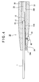
- Fig. 4 shows a cross section of a grip 30 according to third embodiment of the present invention.
- the third embodiment differs from the first and the second embodiments in the arrangement for holding the main scale 1.
- a slide member 39 in contact with the main scale 1 at two points on the component 33 side in the first through hole 34 is provided as a separate body in the third embodiment.
- the slide member is a flat plate extending in the longitudinal direction of the main scale 1 and having recessed cross section.
- the outside bottom center of the slide member 39 is pushed by a fixing screw 40 to bring two projections 39A of the slide member 39 into contact with the main scale 1.
- a female screw is cut on the grip 30 for the fixing screw 40 to press the slide member 39.
- a spot facing hole 41 is provided on the component 33 for the fixing screw 40 not to greatly protrude from the grip 30.
- the pressing force of the slide member 39 is set so that the grip 30 can move in the longitudinal direction of the main scale 1 in a relatively low force and can stop in measuring dimension.
- Fig. 5 shows a cross section of a grip 30 according to fourth embodiment of the present invention.
- a feature of the fourth embodiment is a provision of a turnable movable member 42.
- the component 33 of the grip 30 is separated in the longitudinal direction thereof approximately at the width center to form the movable member 42.
- a groove 45 of U-shaped cross section is provided at approximately longitudinal center thereof along the entire width direction.
- a turn shaft 44 is accommodated in the groove 45 of U-shaped cross section.
- Two coil springs 43 as biasing means are helically wound around the cylindrical surface of the turn shaft 44.
- the movable member 42 When the grip 30 is moved on the main scale 1 during measurement, the movable member 42 is turned by the finger of the hand holding the grip 30 against the coil spring 43 (see double-dotted line in Fig. 5) to eliminate biasing force of the movable member relative to the main scale 1.
- the grip 30 is moved in the condition, and, when the grip 30 is moved to an appropriate position, the finger is released from the movable member 42. Then, the movable member 42 is turned by the coil spring 43 to be in contact with the main scale, where measurement is conducted.
- Figs. 6 and 7 are illustrations of grip 30 according to fifth embodiment.
- a feature of the fifth embodiment is that the grip 30 can be post-attached to an existing caliper.
- a pair of holding portions 55 and 56 for holding the main scale 1 in depth direction and being slidable relative to the main scale 1 is provided to the tube-shaped grip body covering the main scale 1, i.e. the inside (inner opposing sides with the first through hole 34A therebetween) of the components 32 and 33 constituting the grip body.
- First grip component 49A of approximate diamond-shape including a first holding portion 56 of the holding portions 55 and 56 is separated from the component 33 from a parting line 54 and is turnable relative to the component 33 through a turn shaft 50.
- the first grip component 49A is displaceable in a direction for the first holding portions 56 and a second holding portion 55 are separated (up and down direction in Fig. 7) relative to a second grip component 49B (the component 32 and the component 33 except for the first grip component 49A). Accordingly, when the holding portion 56 is displaced to the lower direction in Fig. 7 relative to the holding portion 55, one side ofthe first through hole 34A is opened, through which the other end of the main scale 1 can be inserted to the second through hole 34B.
- a fitting 57 for engaging the first grip component 49A and the second grip component 49B while holding the main scale 1 by the pair of holding portions 55 and 56 is provided between the first grip component 49A and the second grip component 49B (the component 32 and the component 33 except for the first grip component 49A).
- the fitting 57 is composed of a recess 53 on the second grip component 49B formed on the upper wall of the first through hole 34A and a projection 52 provided on the upper end of the first grip component 49A to be engaged with the recess 53.
- the positional relationship between the recess 53 and the projection 52 is set so that the pair of holding portions 55 and 56 hold the main scale 1 with a predetermined force (force capable of sliding and stopping the grip 30) when the projection 52 is engaged in the recess 53.
- the positional relationship between the recess 53 and the projection 52 is set so that the projection 52 engages with the inside of the recess 53 while causing slight elastic deformation of the first grip component 49A when the pair of holding portions 55 and 56 hold the main scale 1 with a predetermined force.
- a claw 51 to be engaged with the upper end of the main scale 1 when the projection 52 engages with the inside of the recess 53 is integrally formed on the upper end of the first grip component 49A.
- the first grip component 49A is elastically deformed in a direction (depth direction of the main scale 1) away from the main scale 1 so that the claw 51 of the first grip component 49A is detached from the upper end of the main scale 1.
- the first grip component 49A is turned (clockwise in Fig. 7).
- a side of the first through hole 34A is opened, from which the other end of the main scale 1 is inserted to the second through hole 34B.
- the first grip component 49A is turned in a direction to return to original condition (anticlockwise in Fig. 7) so that the projection 52 of the first grip component 49A is engaged with the inside of the recess 53 and the claw 51 is engaged with the upper end of the main scale 1.
- the clockwise (in Fig. 7) turn of the first grip component 49A is restricted by the claw 51 and the pair of holding portions 55 and 56 hold the main scale 1, so that the grip 30 can be stopped at a desired position relative to the main scale 1 in measuring dimension and can be moved with relatively low force during movement.
- the grip 30 may be rectangular solid and multiple projections may be provided on the surface thereof.
- the shape of the grip 30 is not limited.
- the material of the grip 30 may not be plastic.
- other material such as rubber may be used. Rubber having appropriate rigidity deforms when being gripped by hand to clamp the main scale 1 and returns to the original shape when the hand is released to eliminate the clamp force to the main scale 1.
- Other alternative materials for the grip may be wood and aluminum. Wood is as light as plastic and much air is included in the fibers thereof, so that heat insulation thereof is superior.
- the aluminum has low specific gravity of one third of steel and the color thereof is similar to the main scale 1 and the slider 11, so that appearance unity can be generated to express luxury touch.
- the main scale 1 may not be sandwiched in connecting the components 32 and 33, but the component projecting in the thickness direction of the other end of the main scale 1 may be detached and the main scale 1 may be inserted to a hole of an integrally-molded tube-shaped grip 30, and the detached component may be attached again. Accordingly, the number of the components can be reduced as compared to an arrangement connecting the two components 32 and 33.
- the grip 30 may be fixed by inserting a male screw into a female crew formed in the grip 30 from the outside of the grip 30 and directly screwing the main scale 1 by the male screw.
- the male screw may be loosened in moving the grip. Accordingly, the grip 30 can be moved without sliding against the main scale 1 and the slide member 39 is not necessary to be provided, thereby reducing production cost.
- the rib 38 and the plate spring 37 are provided to the component 33 in the above embodiments, the rib and plate spring may be provided on the component 32.
- the shape of the rib 38 may not be semi-cylindrical in the second embodiment.
- the shape may be rectangular solid, which may be any shape as long as the rib can be slid with relatively low force.
- a projection integrally molded with the movable member 42 is formed on the movable member 42 in the fourth embodiment, the shape of the projection may not be semi-cylindrical. Any shape of the projection may be used as long as the grip 30 can be stopped relative to the main scale 1 in measuring the dimension.
- vernier scale caliper is specifically described in the above embodiments, the present invention can be applied to digital display caliper and dial display caliper.
- the present invention can be used not only to the caliper but the grip of itself.
Landscapes
- Physics & Mathematics (AREA)
- General Physics & Mathematics (AREA)
- Length-Measuring Instruments Using Mechanical Means (AREA)
Abstract
Description
- The present invention relates to a caliper and a caliper grip. More specifically, it relates to a caliper having a grip movable relative to a main scale and a caliper grip.
- Vernier scale caliper having a main scale provided with main scale graduations formed along the longitudinal direction of the main scale and a slider with vernier graduations formed thereon, a dial display caliper that converts a movement of a slider into rotation of a dial pointer, and a digital display caliper that converts a movement of the slider into an electric signal by a photoelectric, an electrostatic or a magnetic encoder and digitally displays the movement in accordance with the signal on a digital display are conventionally known.
- In measuring with such conventional calipers, workpiece is grabbed by one hand and a main scale is grasped with the other hand, where a slider is moved along the main scale while applying thumb of the other hand to the slider to bring an inner or outer jaw provided to the main scale and the slider into contact with the target portions of the workpiece. The dimension of the workpiece etc. can be obtained from the main scale graduation and vernier graduation (in vernier scale caliper), dial pointer (in dial display caliper) or indication on the digital display (in digital display caliper).
- However, since the slider has to be moved while grasping the main scale with one hand during measurement, following disadvantages occurred in the conventional calipers.
- (a) Since the main scale has rectangular cross section in order to allow the movement of the slider, it is difficult to hold the main scale with the one hand. Especially, when the workpiece is to be measured while moving the slider is moved to a point around effective measurement range relative to the main scale, little space is left on the main scale to be held. For instance, when a caliper having effective measurement range of 10cm is used to measure a dimension around 10cm, since the slider is moved to a position near a distal end of the main scale, little space is left on the main scale to be grasped.
- (b) Further, since the measurement is conducted while directly holding the main scale with one hand, the heat of the hand is transferred to the main scale, which can influence on measurement result. Especially, since electrode is buried along the longitudinal direction of the main scale in a digital display caliper, the heat of the hand can influence on the measurement accuracy.
- (c) The worker may sometimes hold the main scale with hand adhered with oil in a factory. In such environment, the graduation of vernier scale caliper may get dirty by oil etc., so that legibility is deteriorated. Further, when a worker conducts measurement while holding the main scale with hand adhered with chip etc., the chip may damage the electrode of digital display caliper.
-
- Accordingly, the applicant of the present application has proposed a caliper for overcoming the above disadvantages (see US Patent No. 5,483,751), in which a tube-shaped synthetic-resin cover covering the main scale is attached to the slider.
- According to the above arrangement, the synthetic-resin cover is held with one hand and the slider is moved along the longitudinal direction of the main scale while applying the finger cushion of the thumb of the hand to a press roller attached to the slider, thereby bringing the measuring jaw into contact with a target portion of a workpiece.
- Accordingly, since measurement can be conducted while holding the tube-shaped cover having a design enabling easy holding without holding the main scale, the above disadvantage of difficulty in holding the rectangular-cross-sectional main scale can be avoided. There is no problem of little space for holding the main scale in measuring a dimension around the effective measurement range. Further, since synthetic resin of low thermal conductivity is used for the tube-shaped cover, the heat is hardly transferred to the main scale. Since the cover is held without directly holding the main scale, the contamination by oil and chip adhered on hand can be avoided.
- However, since the slider has to be specially machined in attaching the cover to the slider in the conventional caliper (US Patent No. 5,483,751), troublesome work and considerable production cost are necessary therefor.
- A caliper according to an aspect of the present invention has: a main scale having a first measuring jaw; a slider movable along a longitudinal direction of the main scale and having a second measuring jaw to be in contact with a workpiece together with the first measuring jaw; and a tube-shaped grip provided on a side of the main scale opposite to the measuring jaws relative to the slider, the grip covering the main scale and being movable in the longitudinal direction of the main scale.
- According to the above arrangement, after displacing the grip to a position capable of measuring a dimension slightly greater than a target portion, the grip is held with one hand and the slider is moved while pushing the slider with the thumb of the one hand. While the measuring jaw of the slider and the measuring jaw of the main scale are in contact with the workpiece by moving the slider, the dimension between the measuring jaws, i.e. the dimension of the workpiece, is read. The dimension of the workpiece is read by a main graduation of the main scale and a vernier graduation of the slider, the graduation coincident with the pointer of a dial of a dial display caliper and a numeral on a digital display of a dial display caliper.
- Accordingly, since the slider can be manipulated while holding the grip, difficulty in holding the rectangular-cross-sectional main scale and the problem of little holding space on the main scale when the slider is moved relative to the main scale to a point around the effective measurement range can be resolved. Since the heat is not directly transferred to the main scale by holding the grip with hand, deterioration of dimension accuracy by heat can be reduced. Since it is not necessary to hold the main scale directly with one hand, difficulty in reading the graduation of the vernier scale caliper caused by holding the main scale with oil-stained hand and damage on the electrode caused by chips adhered on hand can be prevented. Since the grip is not necessary to be connected to the slider, no work and processing for connecting the grip to the slider is required, thus reducing cost therefor.
- In the above caliper, a plate spring slidable relative to the main scale when the grip is moved in the longitudinal direction of the main scale may preferably be provided on an inner wall of the grip.
- According to the above arrangement, since the spring force can be changed by adjusting shape and material of the spring portion of the plate spring, the grip can be adjusted to be stopped in measuring dimension and moved with relatively low force during movement.
- A rib slidable relative to the main scale when the grip is moved in the longitudinal direction of the main scale may preferably be provided on an inner wall of the grip.
- According to the above arrangement, since the pressing force of the grip toward the main scale can be changed in accordance with the size and shape of the rib, the grip can be adjusted to be stilled in measuring dimension and moved with relatively low force during movement.
- A slide member independent of the grip may preferably be provided between the grip and the main scale.
- According to the above arrangement, since original slide condition can be recovered by exchanging the slide member as one of the components of the grip when the slide member is worn down, the cost can be reduced as compared to an arrangement for exchanging the entire grip.
- The grip may preferably include a grip body covering at least a part of the main scale and a movable member turnably supported by the grip body through a turn shaft and having an end adapted to be in contact with the main scale, and a biasing means for biasing the movable member in a direction for the end of the movable member to be in contact with the main scale.
- According to the above arrangement, in moving the grip, the movable member is turned in a direction for an end of the movable member to be away from the main scale against the biasing means and the grip is moved in the longitudinal direction of the main scale. Since the grip is moved while the movable member is out of contact with the main scale, no abrasion is caused by slide movement and the grip can be moved with low force. When the movable member is turned by the biasing means at a desired position, an end of the movable member is in contact with the main scale and the grip is stilled at the position. The slider can be moved by holding the grip at the position. Even when the grip has been assembled, the main scale can be inserted between the grip body and the movable member by turning the movable member against the biasing means in a direction for an end to move away from the main scale, so that the grip can be easily attached to various existing calipers only by turning the movable member at a desired position by the biasing means and the grip can be detached from the caliper only by turning the movable member against the biasing means.
- A pair of holding portions for holding the main scale and slidable relative to the main scale may preferably be formed inside the grip, a first grip component including a first holding portion of the pair of holding portions may preferably be displaceable relative to a second grip component including a second holding portion of the pair of holding portions in a direction for the first holding portion to move away from the second holding portion, and a fitting for mutually engaging the first grip component and the second grip component when the main scale is held by the pair of holding portions may preferably be provided.
- According to the above arrangement, since the gap between the pair of holding portions is enlarged by displacing the first grip component in a direction for widening the gap between the holding portions, the main scale can be inserted into the gap. After the first grip component is displaced to the second grip component in a direction for the gap between the holding portions to return to original condition, both of the grip components are mutually engaged by the fitting. Then, the pair of holding portions hold the main scale, so that the grip can be stilled at any position relative to the main scale ofthe caliper and can be moved with a relatively low force during movement.
- Accordingly, the grip can be attached and detached to existing calipers without special processing and the grip can be stilled at any position relative to the main scale of the caliper and can be moved with a relatively low force during movement.
- A caliper grip according to another aspect of the present invention for use with a caliper including a main scale having a first measuring jaw and a slider movable along a longitudinal direction of the main scale having a second measuring jaw to be in contact with a workpiece together with the first measuring jaw is formed in a tube-shape for covering the main scale, and is provided with means to enable the caliper grip to be movable on the main scale and stoppable at a desired position on the main scale.
- According to the above arrangement, the same function and advantages as the caliper of the present invention can be obtained.
- In the above, a pair of holding portions for holding the main scale and slidable relative to the main scale may preferably be formed inside the grip, a first grip component including a first holding portion of the pair of holding portions may preferably be displaceable relative to a second grip component including a second holding portion of the holding portions in a direction for the first holding portion to move away from the second holding portion, and a fitting for mutually engaging the first grip component and the second grip component when the main scale is held by the pair of holding portions may preferably be provided.
- According to the above arrangement, the grip can be attached and detached to existing calipers without special processing and the grip can be stilled at any position relative to the main scale of the caliper and can be moved with a relatively low force during movement.
- Thus, the invention provides a caliper and a caliper grip capable of eliminating the above conventional disadvantages, superior in operability and readability, with the measurement accuracy thereof being hardly influenced by heat from hand and superior in processing work and production cost.
- Some examples of calipers according to the invention will now be described with reference to the accompanying drawings, in which:-
- Fig. 1 is a front elevational view showing a vernier scale caliper according to first embodiment of the present invention;
- Fig. 2 is a cross section taken along Line II-II in Fig. 1;
- Fig. 3 is a cross section showing a primary portion of a caliper according to second embodiment of the present invention;
- Fig. 4 is a cross section showing a primary portion of a caliper according to third embodiment of the present invention;
- Fig. 5 is a cross section showing a primary portion of a caliper according to fourth embodiment of the present invention;
- Figs. 6(A) to 6(C) are cross sections showing a primary portion of a caliper according to fifth embodiment of the present invention, in which Fig. 6(A) is a rear elevational view of the primary portion, Fig. 6(B) is a side elevational view thereof and Fig. 6(C) is a cross section taken along C-C line in Fig. 6(A); and
- Fig. 7 is an illustration showing a caliper grip according to the fifth embodiment of the present invention.
-
- Preferred embodiments of the present invention will be described below with reference to attached drawings. Incidentally, the same reference numerals will be attached to the same components in the following description, thereby omitting or simplifying description thereof.
- Fig. 1 is a front elevational view of a vernier scale caliper. The vernier scale caliper shown in Fig. 1 has a
main scale 1, aslider 11 movable along the longitudinal direction of themain scale 1 and agrip 30 movable in the longitudinal direction of themain scale 1 and stoppable at a desired position. - An inside-
measuring jaw 2 and an outside-measuring jaw 3 are formed on the upper and lower periphery of one end of themain scale 1 integrally with themain scale 1. A depth-measuringdepth bar 16 movable together with theslider 11 protrudes from the other end of themain scale 1. Incidentally,graduations 4 of millimeter unit are provided on themain scale 1 along the longitudinal direction thereof andvernier graduations 5 are provided on theslider 11. - The
slider 11 has an inside-measuringjaw 12 for measuring an inside dimension of a workpiece together with the inside-measuringjaw 2 and an outside-measuringjaw 13 for measuring an outside dimension of the workpiece together with the outside-measuringjaw 3, aclamp screw 14 for fixing theslider 11 relative to themain scale 1, and afinger rest 15 used in moving the slider in the longitudinal direction of themain scale 1. - The
grip 30 is made of plastic having enough rigidity not to be deformed when being grasped by hand, which is formed in a tube covering the main scale with both ends thereof being opened. A material of superior chemical resistance and heat resistance is used for thegrip 30 considering environment of actual use. Fourarcuate dents 31A where four fingers except for thumb are applied are formed on the upper end of thegrip 30 for facilitating holding by hand. Further,arcuate dent 31B is formed on the lower side of thegrip 30 under theslider 11 so that the thumb does not interfere when the thumb is stretched to the finger-rest 15 of theslider 11. - Fig. 2 is a cross section taken along line II-II of Fig. 1. As shown in the Figure, the
grip 30 is constructed by bonding twocomponents main scale 1 in the thickness direction. A throughhole 34 for themain scale 1 to be inserted is formed inside thegrip 30. The throughhole 34 is formed by connecting a first throughhole 34A slightly wider than the thickness of themain scale 1 and a second throughhole 34B wider than the first throughhole 34A approximately at the longitudinal center of thegrip 30, the first throughhole 34A being located adjacent to theslider 11 relative to the second throughhole 34B. - A
projection 17 such as a screw is provided on the other end of themain scale 1, which is projected from themain scale 1 in the depth direction of themain scale 1. Accordingly, when thegrip 30 is moved toward the other end of themain scale 1, theprojection 17 engages to astep 18 formed at the connecting portion of the first throughhole 34A and the second throughhole 34B, thereby restricting the movement of thegrip 30 toward the other end of themain scale 1. - A
plate spring 37 is provided in the first throughhole 34A between thecomponent 33 and the backside of themain scale 1. Acentral portion 37A of theplate spring 37 is bent in an arch shape and both ends 37B of theplate spring 37 are in contact with themain scale 1. Thecentral portion 37A of theplate spring 37 is fixed to thecomponent 33 with apin 36. The biasing force of theplate spring 37 is set so that thegrip 30 can move in the longitudinal direction of the main scale in a relatively low force and stop in measuring dimension. - When a workpiece is measured, a
grip 30 is held with one hand at thearcuate dents 31A provided on thegrip 30 and theslider 11 is moved along the longitudinal direction of themain scale 1 while applying the finger cushion of the thumb of the hand on thefinger rest 15, thereby bringing the inside-measuringjaw 12 or the outside-measuringjaw 13 into contact with the workpiece. The dimension of the workpiece can be measured by reading thevernier graduation 5 where themain scale graduation 4 and thevernier graduation 5 substantially coincide with each other. On the other hand, when a workpiece of around the effective measurement range is measured, thegrip 30 is moved toward the other end of themain scale 1 for measurement. Since the measurement can be conducted while holding thegrip 30, there is no problem of difficulty in holding the grip. - According to the above-described first embodiment, following advantages can be obtained.
- (1) Since the measurement can be conducted while holding the
grip 30, not themain scale 1, the caliper can be easily held as compared to an arrangement directly holding themain scale 1. The grip can be easily held since the fourarcuate dents 31A for applying four fingers except for the thumb is formed on the upper side of themain scale 1 and thearcuate dent 31B for preventing interference with the thumb when the thumb is stretched to theslider 11 side is formed on the lower end of themain scale 1 on the side of theslider 11. - (2) Even when the measurement is conducted around the effective measurement
range, holding space can be retained by moving the
grip 30 toward the other end of themain scale 1. - (3) Since the
grip 30 is held without directly holding themain scale 1 with hand, the influence of the heat transferred from the hand to themain scale 1 can be reduced. Especially, since thegrip 30 is made of plastics in the first embodiment, good heat insulation can be obtained. - (4) Cutting oil can be adhered on the graduation of vernier scale caliper when a
worker holds the
main scale 1 with oil-adhered hand and the graduation becomes difficult to be read. However, since themain scale 1 is not directly held with the hand in the present embodiment, the above problem can be solved. In the same manner, the damage on electrodes of digital display caliper on account of chips can be avoided. - (5) Since no processing is required on the
slider 11, production of the caliper can be facilitated as compared to the conventional cover-type caliper. Further, post-attachment can be easily conducted without much trouble and cost. - (6) The
grip 30 can be moved with a relatively low force and can be stopped during measurement in the longitudinal direction of themain scale 1 by adjusting clamp force to themain scale 1 in accordance with deformation of theplate spring 37 provided to thegrip 30. -
- Fig. 3 shows a cross section of
grip 30 according to a second embodiment of the present invention. The second embodiment differs from the first embodiment in the arrangement for holding themain scale 1. - The
plate spring 37 is provided in the first embodiment and thecentral portion 37A of theplate spring 36 is fixed to thecomponent 33 by thepin 36. In the second embodiment, twosemi-cylindrical ribs 38 spaced apart in the longitudinal direction of themain scale 1 by a predetermined interval are provided on thecomponent 33 side. - The longitudinal direction of the
semi-cylindrical rib 38 is the same as the width direction of themain scale 1. Therib 38 is in contact with themain scale 1 over the entire width of themain scale 1. Themain scale 1 is pressed toward thecomponent 32 by the deformation of therib 38. Incidentally, the pressing force of therib 38 is set so that thegrip 30 can move in the longitudinal direction of themain scale 1 in a relatively low force and can stop in measuring dimension. - According to the second embodiment, following advantage as well as the above advantages (1) to (6) can be obtained.
- (7) Since the clamp force can be obtained by the deformation of the
rib 38, thegrip 30 can be set so that thegrip 30 can move in the longitudinal direction of themain scale 1 with a relatively low force and can stop in measuring dimension by adjusting the size of the rib as a parameter. -
- Fig. 4 shows a cross section of a
grip 30 according to third embodiment of the present invention. The third embodiment differs from the first and the second embodiments in the arrangement for holding themain scale 1. - In contrast to the arrangement of the first embodiment using the
plate spring 37 and the second embodiment using therib 38, aslide member 39 in contact with themain scale 1 at two points on thecomponent 33 side in the first throughhole 34 is provided as a separate body in the third embodiment. - The slide member is a flat plate extending in the longitudinal direction of the
main scale 1 and having recessed cross section. The outside bottom center of theslide member 39 is pushed by a fixingscrew 40 to bring twoprojections 39A of theslide member 39 into contact with themain scale 1. A female screw is cut on thegrip 30 for the fixingscrew 40 to press theslide member 39. Aspot facing hole 41 is provided on thecomponent 33 for the fixingscrew 40 not to greatly protrude from thegrip 30. The pressing force of theslide member 39 is set so that thegrip 30 can move in the longitudinal direction of themain scale 1 in a relatively low force and can stop in measuring dimension. - According to the third embodiment, following advantages as well as the above advantages (1) to (6) can be obtained.
- (8) Since the clamp force of the
slide member 39 toward themain scale 1 can be adjusted by the fixingscrew 40, thegrip 30 can be set so that thegrip 30 moves in the longitudinal direction of themain scale 1 with a relatively low force. - (9) Since the
slide member 39 can return to original slide condition by exchanging theslide member 39 as one of the components of thegrip 30 even when theslide member 39 is worn down, the maintenance of the caliper can be inexpensively conducted as compared with an arrangement exchanging theentire grip 30. - (10) Though the thickness of the
grip 30 around the position for the fixingscrew 40 to be screwed is reduced toward theslider 11, since the longitudinal direction of the fixingscrew 40 is perpendicular to the bottom surface of thespot facing hole 41, the protrusion length of the fixingscrew 40 from the surface of thegrip 30 can be reduced, and the fixingscrew 40 can be accommodated below the surface of thegrip 30. When the fixingscrew 40 is accommodated under the surface of thegrip 30, the damage of the plastic male screw caused by hooking the fixingscrew 40 to some objects can be prevented. -
- Fig. 5 shows a cross section of a
grip 30 according to fourth embodiment of the present invention. A feature of the fourth embodiment is a provision of a turnablemovable member 42. - Specifically, the
component 33 of thegrip 30 is separated in the longitudinal direction thereof approximately at the width center to form themovable member 42. Agroove 45 of U-shaped cross section is provided at approximately longitudinal center thereof along the entire width direction. Aturn shaft 44 is accommodated in thegroove 45 of U-shaped cross section. Twocoil springs 43 as biasing means are helically wound around the cylindrical surface of theturn shaft 44. - In assembling the grip, after one end (center side end in Fig. 5) of the
coil spring 43 is inserted to the throughhole 47 provided on themovable member 42, theturn shaft 44 is fitted to thegroove 45 of the U-shaped cross section. Then, simultaneously with inserting the other end of thecoil spring 43 to aninsert hole 48 provided on thecomponent 33, theturn shaft 44 is fitted to agroove 46 of U-shaped cross section provided on thecomponent 33. At this time, the one end of themovable member 42 is pressed to themain scale 1 by virtue of the biasing force of thecoil spring 43. - According to the above arrangement, when a side of the movable member remote from the
slider 11 relative to theturn shaft 44 is turned toward the second throughhole 34B, the slide surface of themovable member 42 against themain scale 1 on theslider 11 side relative to theturn shaft 44 is moved away from the back surface of themain scale 1. - When the
grip 30 is moved on themain scale 1 during measurement, themovable member 42 is turned by the finger of the hand holding thegrip 30 against the coil spring 43 (see double-dotted line in Fig. 5) to eliminate biasing force of the movable member relative to themain scale 1. Thegrip 30 is moved in the condition, and, when thegrip 30 is moved to an appropriate position, the finger is released from themovable member 42. Then, themovable member 42 is turned by thecoil spring 43 to be in contact with the main scale, where measurement is conducted. - According to the fourth embodiment, following advantages as well as the above advantages (1) to (6) can be obtained.
- (11) Since it is not necessary to slide the
movable member 42 relative to themain scale 1 in moving thegrip 30, thegrip 30 can be moved with a light force and no anti-friction problem occurs. -
- Figs. 6 and 7 are illustrations of
grip 30 according to fifth embodiment. A feature of the fifth embodiment is that thegrip 30 can be post-attached to an existing caliper. - Specifically, a pair of holding
portions main scale 1 in depth direction and being slidable relative to themain scale 1 is provided to the tube-shaped grip body covering themain scale 1, i.e. the inside (inner opposing sides with the first throughhole 34A therebetween) of thecomponents -
First grip component 49A of approximate diamond-shape including a first holdingportion 56 of the holdingportions component 33 from aparting line 54 and is turnable relative to thecomponent 33 through aturn shaft 50. In other words, thefirst grip component 49A is displaceable in a direction for thefirst holding portions 56 and asecond holding portion 55 are separated (up and down direction in Fig. 7) relative to asecond grip component 49B (thecomponent 32 and thecomponent 33 except for thefirst grip component 49A). Accordingly, when the holdingportion 56 is displaced to the lower direction in Fig. 7 relative to the holdingportion 55, one side ofthe first throughhole 34A is opened, through which the other end of themain scale 1 can be inserted to the second throughhole 34B. - A fitting 57 for engaging the
first grip component 49A and thesecond grip component 49B while holding themain scale 1 by the pair of holdingportions first grip component 49A and thesecond grip component 49B (thecomponent 32 and thecomponent 33 except for thefirst grip component 49A). The fitting 57 is composed of arecess 53 on thesecond grip component 49B formed on the upper wall of the first throughhole 34A and aprojection 52 provided on the upper end of thefirst grip component 49A to be engaged with therecess 53. The positional relationship between therecess 53 and theprojection 52 is set so that the pair of holdingportions main scale 1 with a predetermined force (force capable of sliding and stopping the grip 30) when theprojection 52 is engaged in therecess 53. In other words, the positional relationship between therecess 53 and theprojection 52 is set so that theprojection 52 engages with the inside of therecess 53 while causing slight elastic deformation of thefirst grip component 49A when the pair of holdingportions main scale 1 with a predetermined force. Incidentally, aclaw 51 to be engaged with the upper end of themain scale 1 when theprojection 52 engages with the inside of therecess 53 is integrally formed on the upper end of thefirst grip component 49A. - In the above arrangement, the
first grip component 49A is elastically deformed in a direction (depth direction of the main scale 1) away from themain scale 1 so that theclaw 51 of thefirst grip component 49A is detached from the upper end of themain scale 1. In this condition, thefirst grip component 49A is turned (clockwise in Fig. 7). Then, a side of the first throughhole 34A is opened, from which the other end of themain scale 1 is inserted to the second throughhole 34B. Thefirst grip component 49A is turned in a direction to return to original condition (anticlockwise in Fig. 7) so that theprojection 52 of thefirst grip component 49A is engaged with the inside of therecess 53 and theclaw 51 is engaged with the upper end of themain scale 1. Then, the clockwise (in Fig. 7) turn of thefirst grip component 49A is restricted by theclaw 51 and the pair of holdingportions main scale 1, so that thegrip 30 can be stopped at a desired position relative to themain scale 1 in measuring dimension and can be moved with relatively low force during movement. - According to the fifth embodiment, following advantages as well as the above advantages (1) to (6) can be obtained.
- (12) The
grip 30 can be attached and detached to various existing calipers after being assembled. - (13) Since the clamp force of the pair of holding
portions first grip component 49A and thesecond grip component 49B when thegrip 30 is attached to themain scale 1, thegrip 30 can be set so that thegrip 30 is stilled while measuring dimension and moved with relatively low force during movement. - (14) Since the
grip 30 is composed of only three components of thecomponent 32, thegrip components 49A and thecomponent 33 except for thegrip component 49A, little trouble is necessary for assembling the grip. -
- Incidentally, the scope of the present invention is not restricted to the calipers described with reference to above embodiments, but includes following modifications.
- For instance, the
grip 30 may be rectangular solid and multiple projections may be provided on the surface thereof. In other words, the shape of thegrip 30 is not limited. - The material of the
grip 30 may not be plastic. For instance, other material such as rubber may be used. Rubber having appropriate rigidity deforms when being gripped by hand to clamp themain scale 1 and returns to the original shape when the hand is released to eliminate the clamp force to themain scale 1. Other alternative materials for the grip may be wood and aluminum. Wood is as light as plastic and much air is included in the fibers thereof, so that heat insulation thereof is superior. The aluminum has low specific gravity of one third of steel and the color thereof is similar to themain scale 1 and theslider 11, so that appearance unity can be generated to express luxury touch. - Further, in the first to third embodiments, the
main scale 1 may not be sandwiched in connecting thecomponents main scale 1 may be detached and themain scale 1 may be inserted to a hole of an integrally-molded tube-shapedgrip 30, and the detached component may be attached again. Accordingly, the number of the components can be reduced as compared to an arrangement connecting the twocomponents - The
grip 30 may be fixed by inserting a male screw into a female crew formed in thegrip 30 from the outside of thegrip 30 and directly screwing themain scale 1 by the male screw. The male screw may be loosened in moving the grip. Accordingly, thegrip 30 can be moved without sliding against themain scale 1 and theslide member 39 is not necessary to be provided, thereby reducing production cost. - Though the
rib 38 and theplate spring 37 are provided to thecomponent 33 in the above embodiments, the rib and plate spring may be provided on thecomponent 32. - The shape of the
rib 38 may not be semi-cylindrical in the second embodiment. For example, the shape may be rectangular solid, which may be any shape as long as the rib can be slid with relatively low force. Though a projection integrally molded with themovable member 42 is formed on themovable member 42 in the fourth embodiment, the shape of the projection may not be semi-cylindrical. Any shape of the projection may be used as long as thegrip 30 can be stopped relative to themain scale 1 in measuring the dimension. - Though vernier scale caliper is specifically described in the above embodiments, the present invention can be applied to digital display caliper and dial display caliper.
- The present invention can be used not only to the caliper but the grip of itself.
Claims (8)
- A caliper, comprising:a main scale (1) having a first measuring jaw (2,3);a slider (11) movable along a longitudinal direction of the main scale (1) and having a second measuring jaw (12,13) to be in contact with a workpiece together with the first measuring jaw (2,3); anda tube-shaped grip (30) provided on a side of the main scale (1) opposite to the measuring jaws relative to the slider, the grip covering the main scale and being movable in the longitudinal direction of the main scale.
- The caliper according to claim 1, wherein a plate spring (37) slidable relative to the main scale (1) when the grip (30) is moved in the longitudinal direction of the main scale is provided on an inner wall of the grip.
- The caliper according to claim 1, wherein a rib (38) slidable relative to the main scale (1) when the grip (30) is moved in the longitudinal direction of the main scale is provided on an inner wall of the grip.
- The caliper according to claim 1, wherein a slide member (39) independent of the grip is provided between the grip and the main scale.
- The caliper according to claim 1, wherein the grip (30) includes a grip body covering at least a part of the main scale and a movable member (42) turnably supported by the grip body through a turn shaft (44) and having an end adapted to be in contact with the main scale (1), and a biasing means (43) for biasing the movable member in a direction for the end of the movable member to be in contact with the main scale.
- The caliper according to claim 1, wherein a pair of holding portions (55,56) for holding the main scale (1)and slidable relative to the main scale are formed inside the grip (30), and wherein a first grip component (49A) including a first holding portion (56) of the pair of holding portions is displaceable relative to a second grip component (49B) including a second holding portion (55) of the pair of holding portions in a direction for the first holding portion to move away from the second holding portion, and
wherein a fitting (57) for mutually engaging the first grip component and the second grip component when the main scale is held by the pair of holding portions is provided. - A caliper grip for use with a caliper including a main scale (1) having a first measuring jaw (2,3) and a slider (11) movable along a longitudinal direction of the main scale having a second measuring jaw to be in contact with a workpiece together with the first measuring jaw,
the caliper grip (30) being formed in a tube-shape for covering the main scale, and being provided with means to enable the caliper grip to be movable on the main scale and stoppable at a desired position on the main scale. - The caliper grip according to claim 7, wherein a pair of holding portions (55,56) for holding the main scale and slidable relative to the main scale are formed inside the grip (30), and wherein a first grip component (49A) including a first holding portion (56) of the pair of holding portions is displaceable relative to a second grip component (49B) including a second holding portion (55) of the holding portions in a direction for the first holding portion to move away from the second holding portion, and
wherein a fitting (57) for mutually engaging the first grip component and the second grip component when the main scale is held by the pair of holding portions is provided.
Applications Claiming Priority (2)
| Application Number | Priority Date | Filing Date | Title |
|---|---|---|---|
| JP2001023857 | 2001-01-31 | ||
| JP2001023857A JP3546184B2 (en) | 2001-01-31 | 2001-01-31 | Vernier caliper and caliper grip |
Publications (2)
| Publication Number | Publication Date |
|---|---|
| EP1229300A1 true EP1229300A1 (en) | 2002-08-07 |
| EP1229300B1 EP1229300B1 (en) | 2012-02-29 |
Family
ID=18889088
Family Applications (1)
| Application Number | Title | Priority Date | Filing Date |
|---|---|---|---|
| EP02250052A Expired - Lifetime EP1229300B1 (en) | 2001-01-31 | 2002-01-04 | Sliding caliper and grip |
Country Status (4)
| Country | Link |
|---|---|
| US (1) | US6594915B2 (en) |
| EP (1) | EP1229300B1 (en) |
| JP (1) | JP3546184B2 (en) |
| CN (1) | CN1190651C (en) |
Families Citing this family (16)
| Publication number | Priority date | Publication date | Assignee | Title |
|---|---|---|---|---|
| US6834439B2 (en) * | 2002-05-21 | 2004-12-28 | Mitutoyo Corporation | Measuring tool, encoder and producing method of encoder |
| US20050044740A1 (en) * | 2003-08-25 | 2005-03-03 | Hansen Andrew H. | Fractional measuring caliper |
| US7096553B1 (en) * | 2004-04-12 | 2006-08-29 | Autosales, Incorporated | Piston ring sizing device |
| US7681325B2 (en) * | 2006-11-02 | 2010-03-23 | General Electric Company | Apparatus for measuring a turbine blade |
| US7748135B1 (en) | 2008-04-02 | 2010-07-06 | Pius O Ileogben | Diameter template |
| US7735236B1 (en) | 2008-04-09 | 2010-06-15 | Ileogben Pius O | Pulley gauge |
| US7735237B1 (en) | 2008-05-30 | 2010-06-15 | C.M. Engineering, Llc | Versatile caliper mounting and measurement accessory |
| JP5462061B2 (en) * | 2010-04-19 | 2014-04-02 | 株式会社ミツトヨ | Measuring instrument |
| US8146263B2 (en) * | 2010-08-06 | 2012-04-03 | Hyman Jack Kipnes | Ergonomic vernier caliper base |
| CN102331213B (en) * | 2011-09-26 | 2013-05-01 | 东莞市邦卡量具科技有限公司 | Double-zero-position caliper |
| US8898923B2 (en) * | 2012-12-05 | 2014-12-02 | Mitutoyo Corporation | System and method for setting measurement force thresholds in a force sensing caliper |
| US9372060B1 (en) * | 2014-12-12 | 2016-06-21 | Ronald Howard | Socket and wrench gauge |
| CN104613840B (en) * | 2015-02-13 | 2018-03-30 | 中铁隆昌铁路器材有限公司 | A kind of ω types spring measurement slide calliper rule and measuring method |
| CN105651136A (en) * | 2016-03-31 | 2016-06-08 | 合肥市远大轴承锻造有限公司 | Vernier caliper for measuring chamfer |
| RU175579U1 (en) * | 2017-06-14 | 2017-12-11 | Акционерное Общество Кировский Завод "Красный Инструментальщик" | Vernier caliper |
| JP7772531B2 (en) | 2021-09-08 | 2025-11-18 | 株式会社ミツトヨ | Measuring instrument attachment cover |
Citations (6)
| Publication number | Priority date | Publication date | Assignee | Title |
|---|---|---|---|---|
| CH584881A5 (en) * | 1974-11-22 | 1977-02-15 | Sinoval Ets | Sliding caliper measuring inner and outer surfaces - has two sets of jaws and thumb controlled spring locking mechanism |
| GB2067761A (en) * | 1980-01-22 | 1981-07-30 | Servier Nederland Bv | A Measuring Caliper |
| US4604808A (en) * | 1984-04-26 | 1986-08-12 | Tesa S.A. | Instrument for measuring linear magnitudes |
| JPH0727501A (en) * | 1993-07-08 | 1995-01-27 | Mitsutoyo Corp | Vernier calipers with communication unit |
| US5483751A (en) | 1992-08-31 | 1996-01-16 | Mitutoyo Corporation | Caliper gauge |
| JPH0949721A (en) * | 1995-08-04 | 1997-02-18 | Mitsutoyo Corp | Butting-type measuring device |
Family Cites Families (3)
| Publication number | Priority date | Publication date | Assignee | Title |
|---|---|---|---|---|
| US1196703A (en) * | 1912-09-17 | 1916-08-29 | Henry Kraut | Tool. |
| GB9304082D0 (en) * | 1993-03-01 | 1993-04-14 | Instron Ltd | A position setting device and securing arrangement for an extensometer |
| GB2357146B (en) * | 1999-10-16 | 2002-12-31 | Segal Alan J | Dental measuring device |
-
2001
- 2001-01-31 JP JP2001023857A patent/JP3546184B2/en not_active Expired - Lifetime
-
2002
- 2002-01-04 EP EP02250052A patent/EP1229300B1/en not_active Expired - Lifetime
- 2002-01-08 US US10/041,439 patent/US6594915B2/en not_active Expired - Lifetime
- 2002-01-29 CN CNB021025789A patent/CN1190651C/en not_active Expired - Fee Related
Patent Citations (6)
| Publication number | Priority date | Publication date | Assignee | Title |
|---|---|---|---|---|
| CH584881A5 (en) * | 1974-11-22 | 1977-02-15 | Sinoval Ets | Sliding caliper measuring inner and outer surfaces - has two sets of jaws and thumb controlled spring locking mechanism |
| GB2067761A (en) * | 1980-01-22 | 1981-07-30 | Servier Nederland Bv | A Measuring Caliper |
| US4604808A (en) * | 1984-04-26 | 1986-08-12 | Tesa S.A. | Instrument for measuring linear magnitudes |
| US5483751A (en) | 1992-08-31 | 1996-01-16 | Mitutoyo Corporation | Caliper gauge |
| JPH0727501A (en) * | 1993-07-08 | 1995-01-27 | Mitsutoyo Corp | Vernier calipers with communication unit |
| JPH0949721A (en) * | 1995-08-04 | 1997-02-18 | Mitsutoyo Corp | Butting-type measuring device |
Non-Patent Citations (2)
| Title |
|---|
| PATENT ABSTRACTS OF JAPAN vol. 1995, no. 04 31 May 1995 (1995-05-31) * |
| PATENT ABSTRACTS OF JAPAN vol. 1997, no. 06 30 June 1997 (1997-06-30) * |
Also Published As
| Publication number | Publication date |
|---|---|
| EP1229300B1 (en) | 2012-02-29 |
| CN1369686A (en) | 2002-09-18 |
| JP2002228402A (en) | 2002-08-14 |
| US6594915B2 (en) | 2003-07-22 |
| CN1190651C (en) | 2005-02-23 |
| US20020100183A1 (en) | 2002-08-01 |
| JP3546184B2 (en) | 2004-07-21 |
Similar Documents
| Publication | Publication Date | Title |
|---|---|---|
| EP1229300B1 (en) | Sliding caliper and grip | |
| EP1892497B1 (en) | Caliper gauge | |
| US9267779B2 (en) | Flexible mount for coupling force actuator to caliper jaw | |
| US12240135B2 (en) | Razor handle with a pivoting portion | |
| US5056238A (en) | Pair of vernier calipers having a protractor | |
| US9212883B2 (en) | Caliper force indicator with tactile or auditory feedback | |
| US6892469B2 (en) | Marking mechanism for a tape measure and tape measure incorporating same | |
| EP3812694B1 (en) | Digital micrometer | |
| EP2131140A2 (en) | Micrometer | |
| US7093373B2 (en) | Displacement measuring instrument | |
| US20200370679A1 (en) | Fluid Conduit Gripping Means | |
| JPS5924967Y2 (en) | displacement detection device | |
| JPH034883Y2 (en) | ||
| JPH11295004A (en) | Inner measuring tool | |
| JPH06185905A (en) | Vernier calipers | |
| EP1166968A1 (en) | Stapler and stapler positioning member | |
| US10300587B2 (en) | Clip installation tool | |
| JP3123375U (en) | Movable vernier | |
| CH634434A5 (en) | GLASS FOR MEASURING INSTRUMENT. | |
| JP3638712B2 (en) | Low measuring force type linear displacement measuring machine | |
| CN208780087U (en) | A kind of slide calliper rule for bar diameter measurement | |
| JPH11281305A (en) | Base material detector | |
| EP1839813A2 (en) | Adjustable spanner with electronic strain gauge function | |
| JPH0749372Y2 (en) | Linear scale | |
| JP3225400B2 (en) | Base material detector |
Legal Events
| Date | Code | Title | Description |
|---|---|---|---|
| PUAI | Public reference made under article 153(3) epc to a published international application that has entered the european phase |
Free format text: ORIGINAL CODE: 0009012 |
|
| AK | Designated contracting states |
Kind code of ref document: A1 Designated state(s): AT BE CH CY DE DK ES FI FR GB GR IE IT LI LU MC NL PT SE TR |
|
| AX | Request for extension of the european patent |
Free format text: AL;LT;LV;MK;RO;SI |
|
| 17P | Request for examination filed |
Effective date: 20030115 |
|
| AKX | Designation fees paid |
Designated state(s): DE FR GB |
|
| 17Q | First examination report despatched |
Effective date: 20090424 |
|
| REG | Reference to a national code |
Ref country code: DE Ref legal event code: R079 Ref document number: 60242290 Country of ref document: DE Free format text: PREVIOUS MAIN CLASS: G01B0003200000 Ipc: G01B0003000000 |
|
| GRAP | Despatch of communication of intention to grant a patent |
Free format text: ORIGINAL CODE: EPIDOSNIGR1 |
|
| RIC1 | Information provided on ipc code assigned before grant |
Ipc: G01B 3/20 20060101ALI20110830BHEP Ipc: G01B 3/00 20060101AFI20110830BHEP |
|
| GRAS | Grant fee paid |
Free format text: ORIGINAL CODE: EPIDOSNIGR3 |
|
| GRAA | (expected) grant |
Free format text: ORIGINAL CODE: 0009210 |
|
| AK | Designated contracting states |
Kind code of ref document: B1 Designated state(s): DE FR GB |
|
| REG | Reference to a national code |
Ref country code: GB Ref legal event code: FG4D |
|
| REG | Reference to a national code |
Ref country code: DE Ref legal event code: R096 Ref document number: 60242290 Country of ref document: DE Effective date: 20120426 |
|
| PLBE | No opposition filed within time limit |
Free format text: ORIGINAL CODE: 0009261 |
|
| STAA | Information on the status of an ep patent application or granted ep patent |
Free format text: STATUS: NO OPPOSITION FILED WITHIN TIME LIMIT |
|
| 26N | No opposition filed |
Effective date: 20121130 |
|
| REG | Reference to a national code |
Ref country code: DE Ref legal event code: R097 Ref document number: 60242290 Country of ref document: DE Effective date: 20121130 |
|
| REG | Reference to a national code |
Ref country code: FR Ref legal event code: PLFP Year of fee payment: 15 |
|
| REG | Reference to a national code |
Ref country code: FR Ref legal event code: PLFP Year of fee payment: 16 |
|
| REG | Reference to a national code |
Ref country code: FR Ref legal event code: PLFP Year of fee payment: 17 |
|
| REG | Reference to a national code |
Ref country code: DE Ref legal event code: R082 Ref document number: 60242290 Country of ref document: DE Representative=s name: KEIL & SCHAAFHAUSEN PATENTANWAELTE PARTGMBB, DE Ref country code: DE Ref legal event code: R082 Ref document number: 60242290 Country of ref document: DE Representative=s name: KEIL & SCHAAFHAUSEN PATENT- UND RECHTSANWAELTE, DE |
|
| PGFP | Annual fee paid to national office [announced via postgrant information from national office to epo] |
Ref country code: GB Payment date: 20200123 Year of fee payment: 19 Ref country code: DE Payment date: 20200121 Year of fee payment: 19 |
|
| PGFP | Annual fee paid to national office [announced via postgrant information from national office to epo] |
Ref country code: FR Payment date: 20200121 Year of fee payment: 19 |
|
| REG | Reference to a national code |
Ref country code: DE Ref legal event code: R119 Ref document number: 60242290 Country of ref document: DE |
|
| GBPC | Gb: european patent ceased through non-payment of renewal fee |
Effective date: 20210104 |
|
| PG25 | Lapsed in a contracting state [announced via postgrant information from national office to epo] |
Ref country code: FR Free format text: LAPSE BECAUSE OF NON-PAYMENT OF DUE FEES Effective date: 20210131 |
|
| PG25 | Lapsed in a contracting state [announced via postgrant information from national office to epo] |
Ref country code: GB Free format text: LAPSE BECAUSE OF NON-PAYMENT OF DUE FEES Effective date: 20210104 Ref country code: DE Free format text: LAPSE BECAUSE OF NON-PAYMENT OF DUE FEES Effective date: 20210803 |