EP1228950A2 - Cab enclosure construction - Google Patents
Cab enclosure construction Download PDFInfo
- Publication number
- EP1228950A2 EP1228950A2 EP02250678A EP02250678A EP1228950A2 EP 1228950 A2 EP1228950 A2 EP 1228950A2 EP 02250678 A EP02250678 A EP 02250678A EP 02250678 A EP02250678 A EP 02250678A EP 1228950 A2 EP1228950 A2 EP 1228950A2
- Authority
- EP
- European Patent Office
- Prior art keywords
- door
- guard
- frame
- window
- cab
- Prior art date
- Legal status (The legal status is an assumption and is not a legal conclusion. Google has not performed a legal analysis and makes no representation as to the accuracy of the status listed.)
- Granted
Links
Images




Classifications
-
- B—PERFORMING OPERATIONS; TRANSPORTING
- B62—LAND VEHICLES FOR TRAVELLING OTHERWISE THAN ON RAILS
- B62D—MOTOR VEHICLES; TRAILERS
- B62D33/00—Superstructures for load-carrying vehicles
- B62D33/06—Drivers' cabs
- B62D33/0617—Drivers' cabs for tractors or off-the-road vehicles
- B62D33/0621—Drivers' cabs for tractors or off-the-road vehicles able to be dismantled, folding
Definitions
- the invention relates to cabs for off road land vehicles to protect the driver from adverse environmental conditions.
- Land vehicles such as lift trucks, construction machinery, farm machinery and the like are frequently supplied with a cab enclosure to protect the driver or operator from severe weather, dust, noise or other environmental conditions.
- a vehicle may be originally manufactured without a fully enclosed cab.
- a vehicle may be manufactured and delivered to a dealer or end user with a factory built overhead guard.
- Such guards typically comprise an open framework or network fabricated from sheet stock, tubing and/or other structural steel shapes. It is known for a manufacturer to produce an overhead guard with sheet metal flanges that can be glazed with safety glass or shatter resistant plastic to form a windshield, side lights, and/or rear window in the event that a customer desires an enclosed cab.
- glazing flanges integrated with the factory installed overhead guard, are intended to allow glazing to be fitted at the factory or to facilitate dealer installation of the glazing panels.
- This approach of integrating glazing flanges with a guard offers flexibility in meeting customer's demands.
- dealer installation of glazing may be troublesome because the available personnel may be inexperienced and ill-equipped to perform the necessary tasks.
- the invention provides glazing assemblies particularly suited for dealer or after market installation on factory built overhead guards, particularly those originally manufactured with glazing flanges but originally sold without glazing.
- the glazing assemblies of the invention include conventional safety glass or shatter resistant plastic glazing and a rigid metal frame surrounding the perimeter of the glazing.
- the glazing assemblies are arranged to span the openings in the overhead guard structure. As disclosed, the assemblies are retained on the cab with structural elements that extend through the planes of the original factory glazing flanges to enable the assembles to be mechanically clamped on the guard.
- the ingress and egress areas of the guard are enclosed by prehung door assemblies.
- the disclosed door assemblies include a door jamb proportioned to fit onto strategic parts of the overhead guard.
- a door is hinge-mounted on the specially configured jamb.
- the door assemblies are clamped onto the original overhead guard structure.
- the disclosed glazing and door assemblies can be installed with personnel having no glazing experience with minimal instructional time and with little chance of error.
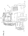
- FIGS. 1 and 2 there is shown an off highway land vehicle in the form of a large lift truck 10.
- a chassis 11 of the lift truck 10 has front wheels 12 and rear wheels 13.
- An engine and transmission (not shown) are mounted on the chassis to propel the truck 10 through the front wheels 12 in a conventional manner.
- Mounted on the chassis 11 is a factory installed overhead guard 14 most clearly shown in FIG. 3.
- the present invention is useful for situations where an original guard is shipped from the factory without glazing or doors and it is desired at a dealer or ultimate user level that the guard be fitted with windows and doors to provide a fully enclosed cab.
- the overhead guard 14 illustrated in FIG. 3 somewhat schematically illustrates a Hyster Lift Truck Model Series H 165XL/210XL.
- the illustrated overhead guard 14 is of a type intended to be optionally fitted with safety glass or other suitable glazing.
- front, side and rear faces 16, 17 and 18 of the guard 14 have window openings 21, 22 and 23 bounded by flat sheet metal structure or flanges.
- the overhead guard 14 is typically fabricated of structural steel elements.
- the front, side and rear faces 16, 17 and 18 of the guard are generally vertical.
- the guard has four generally vertical post structures 24, 25 that support a generally horizontal roof 19.
- the boundaries of the front and side window openings 21, 22 are each planar and are formed by sheet steel of a moderate gauge of about 3/16 inch, for example.
- the boundary of the rear window 23 is similar in character except that it has a wrap around design that comprises a planar back portion bounded at its top and bottom by flat sheet stock and planar side portions generally at right angles to the back portion and each bounded at its top, forward side, and bottom edges by planar sheet stock.
- the rear parts of the guard bounding the rear window 23 can have a moderate gauge of about 3/16 inch, for example.
- a front windshield assembly 31 for closing the front window area or opening 21 of the guard 14, constructed in accordance with the invention, comprises a rigid perimeter frame 32 and safety glazing 42, 43.
- the frame 32 is generally planar and has a generally rectangular configuration corresponding to the shape of the front window area 21.
- the frame 32 is fabricated primarily of sheet steel but can be made of other suitable materials such as aluminum or plastic.
- the outside dimensions of the frame 32 are slightly larger in both the vertical and horizontal directions than corresponding dimensions of the window opening 21 and the frame has openings 34, 36 which collectively are smaller than the corresponding dimensions of the window opening or area 21.
- top, side and bottom elements 37, 38 and 39 of the perimeter frame 32 when installed on the guard 14 each cover a marginal part of adjacent underlying surfaces of the guard front face 16 at the window opening 21 and a peripheral part of the window opening itself.
- the frame 32 includes a muntin or bar 41 dividing the areas forming the upper and lower openings or lights 34, 36.
- the upper main light or opening 34 is preferably glazed with laminated safety glass 42 and the lower light or opening 36 is preferably glazed with clear polycarbonate sheet stock 43 or other suitable shatter-resistant plastic. Both glazing sheets 42, 43 are preferably mounted on the sheet stock of the frame 32 with extruded rubber strips 44, known in the art.
- the windshield assembly 31 is retained on the guard 14 with mechanical fastening elements that extend through the original window opening 21 thereby avoiding structural alteration of the guard 14 and possible compromise of its integrity.
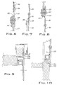
- these fastening elements include a lower Z-strip 46 (FIG. 5) and machine screws 47 (e.g. FIG. 5A).
- the Z-strip 46 which is welded or otherwise fixed to the frame 32 hooks over the lower edge of the window opening 21 to grasp the guard 14 at this location.
- the screws 47 located at spaced locations around the perimeter of the window opening 21 engage threaded holes in associated clamp plates 48, 49 and 50 positioned within the guard 14. As shown for example in FIG.
- the clamp plates 49, 48 are each proportioned to receive its associated screw 47 at a location within the boundary of the window opening 21 and to bear against the inside face of the guard flange surrounding the window opening.
- Spacers 53 such as typically shown in FIG. 5A can be provided between the clamp plates 48 - 50 to generally align the associated clamp plate in parallel relation to the part of the guard structure it clamps against.
- the spacers 53 are preferably welded to the frame 32.
- the threaded holes of the clamp plates 48 - 50 can be provided by weld nuts as shown.
- the glazing sheets 42, 43 are preferably factory mounted on the frame 32 preferably at the factory where the window assembly is made and thus before the windshield assembly 31 is installed on the guard 14. Installation of the assembly 31 is facilitated by the Z-strip 46 which, when hooked over the lower edge of the window opening 21 is capable of supporting the weight of the assembly while the retaining screws 47 are assembled through clearance holes 54 in the frame 32, registered with associated clamp plates 48 - 50 and finally tightened into such clamp plates.
- FIG. 5A shows typical details of the arrangement of a retaining bolt or screw 47 and a clamp plate 49 at points spaced around the perimeter of the window opening 21.
- a front side port window assembly 56 includes a generally triangular perimeter frame 57 fabricated from steel sheet stock and safety glazing 58 in the form of clear polycarbonate or other suitable shatter-resistant glazing sheet material.
- the outside dimensions of the frame 57 are larger than corresponding dimensions of an associated side port opening 22 and the inside dimensions are smaller than the corresponding dimensions of such opening.
- the frame 57 abuts the outside surface of the guard 14 surrounding the port opening 22 and the glazing fits within this opening.
- the frame 57 is held in place by a lower clamp plate 59 and an upper clamp plate 61 positioned against the inside surface of the guard below and above the glazing 58.
- the frame 57 is held against the guard by tightening machine screws 62 assembled through holes 63 in the frame into respective ones of the clamp plates 59, 61. Again, like the windshield assembly 31, the frame 57 is proportioned so that the screw receiving holes 63 are within the boundary of the side port opening 22 so that the need for cutting or drilling holes in the guard or other like alteration is avoided.
- the glazing 58 is held in place against the inner face of the frame 57 by machine screws 66 assembled through aligned holes in these members within the boundary of the side port opening 22 and tightened into nuts 69 on the inside face of the glazing 58.
- a rear windshield assembly 71 comprises a rigid frame 72 and glazing units 85, 88 and 89.
- the frame 72 in the illustrated example, is fabricated from steel sheet stock having cutouts or openings 77, 78 and 79 (FIG. 3) for rear and rear side vision.
- the frame 72 has a generally planar rear section 81 including the two large cutouts 77, 78 and two side sections 82 formed by bending the sheet into a U-shape or wrap around configuration.
- the side sections 82 include the side port cutouts 79.
- a rightward one 77 of the large cutouts is fitted with laminated safety glass 85 or other suitable glazing mounted in a conventional elastomeric extrusion.
- the other large cutout 78 is fitted with a double-hung window frame 88 carrying suitable safety glazing.
- This double-hung frame 88 is mounted in the cut-out 78 with suitable elastomeric extrusion material known in the art.
- a vertical reinforcing bar or mullion 83 is welded to a central part of the rear section 81.
- a Z-strip 84 is welded on the inside lower margin of the rear section 81 to form an inverted channel.
- Glazing units 89 of polycarbonate or other suitable shatter-resistant glazing material are attached to the side sections 82 of the frame 72 over the side port openings 79 by machine screws 86 or other suitable known fastening medium.
- the Z-strip 84 is positioned so that it can be hooked over the lower edge of the rear window area 23 to thereby support the weight of the assembly 71 as it is being installed on the guard.
- the assembly 71 is retained on the guard 14 in a manner like that of the front windshield assembly 31.
- the perimeter elements of the frame 72 surrounding the cutouts 77 - 79 overlie portions of the guard surrounding the rear opening 23 and adjacent areas within the boundary of the opening.
- Machine screws 87 are assembled through holes spaced along the perimeter of the frame 72 and pass through areas of the rear opening 23 and are tightened into retaining plates 91, 92 and 93 positioned on the inside of the guard.
- the plates 91 - 93 bear against the inside surfaces of the guard so that when the screws 86 are fully tightened, the frame 72 is securely held in place on the outside of the guard. Again, as with previously described window assemblies 31, 56 no structural modification of the guard is required for mounting the rear windshield assembly 71.
- the guard 14 is fitted with generally symmetrical right and left hand door assemblies 96.
- the door assemblies 96 each comprise a door 97 "pre-hung" on a door frame 98.
- the door frame 98 is a rectangular steel framework including jambs 101, a header 102 and a threshold 103 all welded or otherwise joined rigidly together.
- the frame members 101 - 103 include outer flanges 104 generally coplanar with each other and adapted to abut the outer face area of the guard 14 surrounding the passage opening 26.
- the door 97 is pivotally mounted to a rearward one of the jambs 101 with a continuous hinge 106.
- a conventional door latch assembly generally indicated at 107 releasably holds a door closed in the frame 98.
- Each door assembly 96 is secured in place in the opening 26 by a plurality of retaining bolts 111 and bracket elements 112 located at vertically spaced locations on the jambs 101.
- the retaining bolts or screws 111 are threaded into internally threaded bosses 113 welded onto the jambs 101.
- the brackets 112 are arranged, when the bolts 111 are tightened to bear against inside surfaces of the guard to draw the flanges 104 of the jambs 101 against the outer surfaces of the guard.
- the door assemblies 96 are secured in place on the guard 14 by clamping elements 111, 112 that develop a grip on both faces of the sides of the guard 14 without requiring structural modification of the guard.
- the roof 19 of the guard can be partially covered with a transparent glazing sheet fitted over the roof opening 115 to enclose this area of the guard.
Landscapes
- Engineering & Computer Science (AREA)
- Chemical & Material Sciences (AREA)
- Combustion & Propulsion (AREA)
- Transportation (AREA)
- Mechanical Engineering (AREA)
- Window Of Vehicle (AREA)
- Body Structure For Vehicles (AREA)
Abstract
Description
Claims (9)
- An off road land vehicle having a cab fabricated with metal sheet material, the cab including at least one window area such as a windshield, the window area being bounded by the sheet material and having a substantially closed boundary, and a glazing unit for enclosing the window area, the glazing unit including a rigid peripheral framework and a sheet of safety glazing carried by the framework, the framework being secured to the cab by fasteners extending through the window area and within its boundary.
- An off road land vehicle as set forth in claim 1, wherein said cab includes an opening for ingress and egress of an operator, a generally rectangular door jamb assembled onto said cab in said opening, a door, adapted to be prehung on said door jamb, said door being hinged on said door jamb.
- An off road land vehicle as set forth in claim 2, wherein said door jamb is secured to said cab by clamping elements disposed on opposite sides of the cab structure forming said ingress and egress opening.
- A method of fitting an overhead guard for an off road vehicle with a door comprising the steps of forming a door frame with a configuration generally complementary to an opening through the side of the guard and including at least two generally vertical sides and a horizontal header, mounting a door on the frame with hinge elaments arranged to support the door for pivotal movement about a generally vertical axis, the door frame and door being arranged to substantially close the opening in the guard when the door is closed on the opening.
- A method as set forth in claim 4, wherein the door frame vertical jamb elements are clamped on parts of the guard.
- A method as set forth in claim 5, wherein the jamb has a threshold.
- A method as set forth in claim 6, wherein said threshold is assembled to vertical parts of said jamb by welding.
- A method of glazing a cab for an off road vehicle having at least a front windshield area surrounded by rigid structure comprising providing a rigid perimeter frame with safety glazing, positioning the perimeter frame with the safety glazing mounted thereon across the window area, securing the perimeter frame to the cab structure with fasteners extending through the window area, the fasteners being arranged so that when tightened, they draw the perimeter frame towards the rigid structure and thereby secure it to the rigid structure.
- A kit for enclosing the overhead guard of an off road vehicle comprising at least one window assembly and one door assembly, the window assembly including a rigid perimeter frame and a safety glazing panel, the safety glazing panel being secured to the perimeter frame and covering an area bounded by the perimeter frame, the window assembly being adapted to overlie the face area of an overhead guard and including retaining structure adapted to extend through a plane defined by the outward facing window frame receiving surfaces of the guard between a pair of generally upright corners of the guard and adapted to engage inwardly facing surfaces of the guard to retain the window frame on the outwardly facing window frame receiving surfaces of the guard, the door assembly including a frame with a generally rectangular configuration including a pair of generally vertical jambs and a door hinged on the frame, the frame including flange elements adapted to engage outwardly facing door frame receiving surfaces of the overhead guard and retaining structure adapted to extend through a plane defined by said door frame receiving surfaces and engage inwardly facing surfaces of the guard to retain the door frame on said outwardly facing door frame receiving surfaces.
Applications Claiming Priority (2)
| Application Number | Priority Date | Filing Date | Title |
|---|---|---|---|
| US09/775,397 US6561572B1 (en) | 2001-01-31 | 2001-01-31 | Cab enclosure construction |
| US775397 | 2001-01-31 |
Publications (3)
| Publication Number | Publication Date |
|---|---|
| EP1228950A2 true EP1228950A2 (en) | 2002-08-07 |
| EP1228950A3 EP1228950A3 (en) | 2003-11-12 |
| EP1228950B1 EP1228950B1 (en) | 2008-10-29 |
Family
ID=25104282
Family Applications (1)
| Application Number | Title | Priority Date | Filing Date |
|---|---|---|---|
| EP02250678A Expired - Lifetime EP1228950B1 (en) | 2001-01-31 | 2002-01-31 | Cab enclosure construction |
Country Status (4)
| Country | Link |
|---|---|
| US (1) | US6561572B1 (en) |
| EP (1) | EP1228950B1 (en) |
| CA (1) | CA2369785C (en) |
| DE (1) | DE60229574D1 (en) |
Cited By (3)
| Publication number | Priority date | Publication date | Assignee | Title |
|---|---|---|---|---|
| CN102392572A (en) * | 2011-07-15 | 2012-03-28 | 上海三一科技有限公司 | Movable door sliding and locking mechanism for crane cab and crane having the same |
| EP3020873A3 (en) * | 2014-11-12 | 2016-06-08 | Echle Hartstahl GmbH | Cabin protection structure for an operator's cab of a working machine |
| US20190264493A1 (en) * | 2018-02-27 | 2019-08-29 | Taylor Made Group, Llc | High strength window or door system |
Families Citing this family (17)
| Publication number | Priority date | Publication date | Assignee | Title |
|---|---|---|---|---|
| JP4201126B2 (en) * | 2003-04-10 | 2008-12-24 | 株式会社小松製作所 | Construction machinery cab |
| GB2430180A (en) * | 2005-09-20 | 2007-03-21 | Agco Sa | Tractor cab roof structure |
| US7614117B2 (en) | 2006-04-25 | 2009-11-10 | Caterpillar S.A.R.L. | Quick-release hinge |
| USD551257S1 (en) | 2006-07-11 | 2007-09-18 | Caterpillar S.A.R.L. | Door for a machine |
| USD598032S1 (en) * | 2006-10-02 | 2009-08-11 | Kubota Corporation | Cabin for a transport vehicle |
| US7731273B2 (en) * | 2008-01-31 | 2010-06-08 | Cnh America Llc | Work vehicle viewing system |
| US8091955B2 (en) * | 2009-04-16 | 2012-01-10 | Clark Equipment Company | Sliding window for work vehicle cab |
| US7938479B2 (en) * | 2009-04-17 | 2011-05-10 | Clark Equipment Company | Releasable door hinge |
| US8336951B2 (en) * | 2009-12-28 | 2012-12-25 | Kawasaki Jukogyo Kabushiki Kaisha | Mud guard structure having windows |
| NL2004954C2 (en) * | 2010-05-31 | 2011-12-01 | Hudson Bay Holding B V | MOBILE DEVICE. |
| US8899654B2 (en) * | 2011-10-02 | 2014-12-02 | General Electric Company | Ingress/egress system and method |
| USD691924S1 (en) * | 2012-05-31 | 2013-10-22 | Michael Glenn Smith | Vehicle cab enclosure |
| KR101879157B1 (en) * | 2018-03-29 | 2018-08-16 | 김학성 | Doors and window frames for forklift cabins mounted without drilling |
| US10947698B2 (en) * | 2019-06-12 | 2021-03-16 | Caterpillar Inc. | Low-profile machine cabin |
| CN110696935A (en) * | 2019-11-18 | 2020-01-17 | 徐工集团工程机械股份有限公司 | Cab and engineering vehicle |
| US11376929B2 (en) * | 2019-12-10 | 2022-07-05 | Hyster-Yale Group, Inc. | Lift truck operator compartment door |
| CA3261263A1 (en) * | 2023-12-29 | 2025-10-31 | LDS Holdings LLC d/b/a Proenclosures | Forklift Cab Enclosure System |
Family Cites Families (22)
| Publication number | Priority date | Publication date | Assignee | Title |
|---|---|---|---|---|
| US2997333A (en) * | 1959-01-05 | 1961-08-22 | Crane Rental Company Inc | All-weather cab enclosure employing removable panels |
| US4079985A (en) | 1975-03-03 | 1978-03-21 | Martin Robert P | Cab for industrial truck |
| US3967859A (en) * | 1975-05-05 | 1976-07-06 | Deere & Company | Vandal latch for preventing removal of a pop-out type vehicle window |
| US4133574A (en) | 1976-10-26 | 1979-01-09 | Martin Robert P | Guard-cab for cold room |
| US4099590A (en) | 1977-02-17 | 1978-07-11 | Martin Sr Robert P | Sound attenuating engine cover |
| USD249254S (en) | 1977-02-17 | 1978-09-05 | Martin Sr Robert P | Lift truck cab |
| US4205874A (en) | 1978-01-13 | 1980-06-03 | Martin Robert P | High-low profile guard |
| US4221274A (en) | 1979-02-12 | 1980-09-09 | Martin Robert P | Lift truck cab with movable back wall portion |
| USD267486S (en) | 1980-08-22 | 1983-01-04 | Martin Jr Robert P | Truck cab |
| US4392669A (en) | 1980-10-24 | 1983-07-12 | Martin Robert P | Cab for lift truck with swing out windshield |
| USD274276S (en) | 1981-09-18 | 1984-06-12 | Martin Jr Robert P | Lift truck cab |
| USD279660S (en) | 1982-09-07 | 1985-07-16 | Martin Jr Robert P | Tractor cab |
| US4619479A (en) | 1985-03-14 | 1986-10-28 | Martin Robert P | Lift truck cab |
| US4688846A (en) | 1985-04-15 | 1987-08-25 | Martin Robert P | Fabric cab |
| US4675933A (en) | 1985-09-19 | 1987-06-30 | Martin Robert P | Offset wiper drive |
| US4702516A (en) | 1986-01-22 | 1987-10-27 | Martin Robert P | Cab construction |
| JPH082760B2 (en) * | 1988-09-16 | 1996-01-17 | 株式会社クボタ | Wheel loader cabin structure |
| USD348553S (en) | 1993-01-21 | 1994-07-05 | Martin Sheet Metal, Inc. | Vehicle cab |
| US5286081A (en) | 1993-01-21 | 1994-02-15 | Martin Sheet Metal, Inc. | Panel cab |
| US6189954B1 (en) * | 1998-12-02 | 2001-02-20 | Martin Sheet Metal, Inc. | Cab enclosure panels |
| US6149228A (en) * | 1998-12-09 | 2000-11-21 | Deere & Company | Modular operator enclosure |
| US6293610B1 (en) * | 2000-02-01 | 2001-09-25 | Jayne A. Howard | Method and apparatus for a door system for golf cart-type street vehicle |
-
2001
- 2001-01-31 US US09/775,397 patent/US6561572B1/en not_active Expired - Lifetime
-
2002
- 2002-01-31 EP EP02250678A patent/EP1228950B1/en not_active Expired - Lifetime
- 2002-01-31 DE DE60229574T patent/DE60229574D1/en not_active Expired - Lifetime
- 2002-01-31 CA CA2369785A patent/CA2369785C/en not_active Expired - Lifetime
Cited By (6)
| Publication number | Priority date | Publication date | Assignee | Title |
|---|---|---|---|---|
| CN102392572A (en) * | 2011-07-15 | 2012-03-28 | 上海三一科技有限公司 | Movable door sliding and locking mechanism for crane cab and crane having the same |
| CN102392572B (en) * | 2011-07-15 | 2014-05-28 | 上海三一科技有限公司 | Movable door sliding and locking mechanism for crane cab and crane having the same |
| EP3020873A3 (en) * | 2014-11-12 | 2016-06-08 | Echle Hartstahl GmbH | Cabin protection structure for an operator's cab of a working machine |
| EP3020873B1 (en) | 2014-11-12 | 2018-01-10 | Echle Hartstahl GmbH | Cabin protection structure for an operator's cab of a working machine |
| US20190264493A1 (en) * | 2018-02-27 | 2019-08-29 | Taylor Made Group, Llc | High strength window or door system |
| US10697230B2 (en) * | 2018-02-27 | 2020-06-30 | Taylor Made Group, Llc | High strength window or door system |
Also Published As
| Publication number | Publication date |
|---|---|
| EP1228950B1 (en) | 2008-10-29 |
| CA2369785C (en) | 2010-04-20 |
| US6561572B1 (en) | 2003-05-13 |
| HK1050169A1 (en) | 2003-06-13 |
| CA2369785A1 (en) | 2002-07-31 |
| EP1228950A3 (en) | 2003-11-12 |
| DE60229574D1 (en) | 2008-12-11 |
Similar Documents
| Publication | Publication Date | Title |
|---|---|---|
| US6561572B1 (en) | Cab enclosure construction | |
| EP1051306B1 (en) | Cab enclosure panels | |
| EP0680431B1 (en) | Panel cab | |
| US5273340A (en) | Cab assembly | |
| US6276748B1 (en) | Lightweight cab/sleeper for trucks | |
| US4702516A (en) | Cab construction | |
| US6134841A (en) | Door system for utility vehicles | |
| EP1188590B1 (en) | Support means for a window | |
| HK1050169B (en) | Cab enclosure construction | |
| CA3085251C (en) | Aftermarket door assembly for extended semi-truck cab | |
| US4658544A (en) | Door assembly | |
| HK1032018B (en) | Cab enclosure panels | |
| JP3739289B2 (en) | Tractor driving cabin | |
| JPH072274Y2 (en) | Vehicle door structure | |
| JP4157220B2 (en) | Packing box structure for van type vehicles | |
| GB2270947A (en) | Glazing assembly for use in the flush double glazing of vehicles. | |
| JPH0211212Y2 (en) | ||
| JPH07132734A (en) | Cabin door panel mounting device | |
| JPH04314619A (en) | Door of tractor cabin | |
| GB2259537A (en) | Window installation | |
| JPH04197827A (en) | Door for car | |
| JPH07277229A (en) | Automotive loading space | |
| JPH04198579A (en) | Window panel raising and lowering device for automobile | |
| GB2275076A (en) | Barrier structure for holding glass |
Legal Events
| Date | Code | Title | Description |
|---|---|---|---|
| PUAI | Public reference made under article 153(3) epc to a published international application that has entered the european phase |
Free format text: ORIGINAL CODE: 0009012 |
|
| AK | Designated contracting states |
Kind code of ref document: A2 Designated state(s): AT BE CH CY DE DK ES FI FR GB GR IE IT LI LU MC NL PT SE TR |
|
| AX | Request for extension of the european patent |
Free format text: AL;LT;LV;MK;RO;SI |
|
| PUAL | Search report despatched |
Free format text: ORIGINAL CODE: 0009013 |
|
| AK | Designated contracting states |
Kind code of ref document: A3 Designated state(s): AT BE CH CY DE DK ES FI FR GB GR IE IT LI LU MC NL PT SE TR |
|
| AX | Request for extension of the european patent |
Extension state: AL LT LV MK RO SI |
|
| 17P | Request for examination filed |
Effective date: 20040511 |
|
| AKX | Designation fees paid |
Designated state(s): BE DE ES FR GB IT |
|
| 17Q | First examination report despatched |
Effective date: 20060407 |
|
| GRAP | Despatch of communication of intention to grant a patent |
Free format text: ORIGINAL CODE: EPIDOSNIGR1 |
|
| GRAS | Grant fee paid |
Free format text: ORIGINAL CODE: EPIDOSNIGR3 |
|
| GRAA | (expected) grant |
Free format text: ORIGINAL CODE: 0009210 |
|
| AK | Designated contracting states |
Kind code of ref document: B1 Designated state(s): BE DE ES FR GB IT |
|
| REG | Reference to a national code |
Ref country code: GB Ref legal event code: FG4D |
|
| REF | Corresponds to: |
Ref document number: 60229574 Country of ref document: DE Date of ref document: 20081211 Kind code of ref document: P |
|
| PG25 | Lapsed in a contracting state [announced via postgrant information from national office to epo] |
Ref country code: ES Free format text: LAPSE BECAUSE OF FAILURE TO SUBMIT A TRANSLATION OF THE DESCRIPTION OR TO PAY THE FEE WITHIN THE PRESCRIBED TIME-LIMIT Effective date: 20090209 |
|
| REG | Reference to a national code |
Ref country code: HK Ref legal event code: GR Ref document number: 1050169 Country of ref document: HK |
|
| PG25 | Lapsed in a contracting state [announced via postgrant information from national office to epo] |
Ref country code: BE Free format text: LAPSE BECAUSE OF FAILURE TO SUBMIT A TRANSLATION OF THE DESCRIPTION OR TO PAY THE FEE WITHIN THE PRESCRIBED TIME-LIMIT Effective date: 20081029 |
|
| PG25 | Lapsed in a contracting state [announced via postgrant information from national office to epo] |
Ref country code: IT Free format text: LAPSE BECAUSE OF FAILURE TO SUBMIT A TRANSLATION OF THE DESCRIPTION OR TO PAY THE FEE WITHIN THE PRESCRIBED TIME-LIMIT Effective date: 20081029 |
|
| PLBE | No opposition filed within time limit |
Free format text: ORIGINAL CODE: 0009261 |
|
| STAA | Information on the status of an ep patent application or granted ep patent |
Free format text: STATUS: NO OPPOSITION FILED WITHIN TIME LIMIT |
|
| 26N | No opposition filed |
Effective date: 20090730 |
|
| REG | Reference to a national code |
Ref country code: FR Ref legal event code: ST Effective date: 20091030 |
|
| PG25 | Lapsed in a contracting state [announced via postgrant information from national office to epo] |
Ref country code: FR Free format text: LAPSE BECAUSE OF NON-PAYMENT OF DUE FEES Effective date: 20090202 |
|
| PGFP | Annual fee paid to national office [announced via postgrant information from national office to epo] |
Ref country code: GB Payment date: 20210111 Year of fee payment: 20 Ref country code: DE Payment date: 20210115 Year of fee payment: 20 |
|
| REG | Reference to a national code |
Ref country code: DE Ref legal event code: R071 Ref document number: 60229574 Country of ref document: DE |
|
| REG | Reference to a national code |
Ref country code: GB Ref legal event code: PE20 Expiry date: 20220130 |
|
| PG25 | Lapsed in a contracting state [announced via postgrant information from national office to epo] |
Ref country code: GB Free format text: LAPSE BECAUSE OF EXPIRATION OF PROTECTION Effective date: 20220130 |