EP1228884A1 - Method and device to prevent foreign metallic object damage in fluid ejection systems using microwave dryers - Google Patents
Method and device to prevent foreign metallic object damage in fluid ejection systems using microwave dryers Download PDFInfo
- Publication number
- EP1228884A1 EP1228884A1 EP02001516A EP02001516A EP1228884A1 EP 1228884 A1 EP1228884 A1 EP 1228884A1 EP 02001516 A EP02001516 A EP 02001516A EP 02001516 A EP02001516 A EP 02001516A EP 1228884 A1 EP1228884 A1 EP 1228884A1
- Authority
- EP
- European Patent Office
- Prior art keywords
- metal
- microwave dryer
- metal detector
- microwave
- detected
- Prior art date
- Legal status (The legal status is an assumption and is not a legal conclusion. Google has not performed a legal analysis and makes no representation as to the accuracy of the status listed.)
- Granted
Links
- 239000012530 fluid Substances 0.000 title claims abstract description 51
- 238000000034 method Methods 0.000 title claims abstract description 16
- 239000002184 metal Substances 0.000 claims abstract description 87
- 229910052751 metal Inorganic materials 0.000 claims abstract description 87
- 238000001514 detection method Methods 0.000 claims abstract description 16
- 238000001035 drying Methods 0.000 claims abstract description 7
- 230000005672 electromagnetic field Effects 0.000 claims abstract description 6
- 230000004044 response Effects 0.000 claims description 12
- 239000007769 metal material Substances 0.000 description 8
- 238000007639 printing Methods 0.000 description 8
- 239000007788 liquid Substances 0.000 description 7
- XEEYBQQBJWHFJM-UHFFFAOYSA-N Iron Chemical compound [Fe] XEEYBQQBJWHFJM-UHFFFAOYSA-N 0.000 description 6
- 230000007723 transport mechanism Effects 0.000 description 5
- 239000000463 material Substances 0.000 description 4
- 229910052742 iron Inorganic materials 0.000 description 3
- 230000003044 adaptive effect Effects 0.000 description 2
- 150000001875 compounds Chemical class 0.000 description 2
- 238000007641 inkjet printing Methods 0.000 description 2
- -1 staples Chemical compound 0.000 description 2
- CWYNVVGOOAEACU-UHFFFAOYSA-N Fe2+ Chemical compound [Fe+2] CWYNVVGOOAEACU-UHFFFAOYSA-N 0.000 description 1
- 238000010521 absorption reaction Methods 0.000 description 1
- 238000007605 air drying Methods 0.000 description 1
- 239000003086 colorant Substances 0.000 description 1
- 230000008878 coupling Effects 0.000 description 1
- 238000010168 coupling process Methods 0.000 description 1
- 238000005859 coupling reaction Methods 0.000 description 1
- 230000008021 deposition Effects 0.000 description 1
- 230000005670 electromagnetic radiation Effects 0.000 description 1
- 238000012840 feeding operation Methods 0.000 description 1
- 150000008040 ionic compounds Chemical class 0.000 description 1
- 230000004048 modification Effects 0.000 description 1
- 238000012986 modification Methods 0.000 description 1
- 230000008569 process Effects 0.000 description 1
- 239000002904 solvent Substances 0.000 description 1
- 230000003068 static effect Effects 0.000 description 1
- 239000000758 substrate Substances 0.000 description 1
Images


Classifications
-
- B—PERFORMING OPERATIONS; TRANSPORTING
- B41—PRINTING; LINING MACHINES; TYPEWRITERS; STAMPS
- B41J—TYPEWRITERS; SELECTIVE PRINTING MECHANISMS, i.e. MECHANISMS PRINTING OTHERWISE THAN FROM A FORME; CORRECTION OF TYPOGRAPHICAL ERRORS
- B41J11/00—Devices or arrangements of selective printing mechanisms, e.g. ink-jet printers or thermal printers, for supporting or handling copy material in sheet or web form
- B41J11/0015—Devices or arrangements of selective printing mechanisms, e.g. ink-jet printers or thermal printers, for supporting or handling copy material in sheet or web form for treating before, during or after printing or for uniform coating or laminating the copy material before or after printing
- B41J11/002—Curing or drying the ink on the copy materials, e.g. by heating or irradiating
- B41J11/0021—Curing or drying the ink on the copy materials, e.g. by heating or irradiating using irradiation
- B41J11/00212—Controlling the irradiation means, e.g. image-based controlling of the irradiation zone or control of the duration or intensity of the irradiation
-
- B—PERFORMING OPERATIONS; TRANSPORTING
- B41—PRINTING; LINING MACHINES; TYPEWRITERS; STAMPS
- B41J—TYPEWRITERS; SELECTIVE PRINTING MECHANISMS, i.e. MECHANISMS PRINTING OTHERWISE THAN FROM A FORME; CORRECTION OF TYPOGRAPHICAL ERRORS
- B41J11/00—Devices or arrangements of selective printing mechanisms, e.g. ink-jet printers or thermal printers, for supporting or handling copy material in sheet or web form
- B41J11/0015—Devices or arrangements of selective printing mechanisms, e.g. ink-jet printers or thermal printers, for supporting or handling copy material in sheet or web form for treating before, during or after printing or for uniform coating or laminating the copy material before or after printing
- B41J11/002—Curing or drying the ink on the copy materials, e.g. by heating or irradiating
- B41J11/0021—Curing or drying the ink on the copy materials, e.g. by heating or irradiating using irradiation
- B41J11/00216—Curing or drying the ink on the copy materials, e.g. by heating or irradiating using irradiation using infrared [IR] radiation or microwaves
Definitions
- the invention relates to fluid ejection systems that use microwave dryers.
- a fluid ejection system such as an ink jet printer, typically has at least one printhead from which droplets of fluid are directed towards a recording medium or recording sheet. Within the printhead, the fluid is contained in a plurality of channels. Droplets of the fluid are expelled as required from orifices or nozzles located at the end of the channels.
- a fluid ejector head may be incorporated into either a carriage type fluid ejection system, a page-width type fluid ejection system, or a combination of the two.
- the carriage type fluid ejection system typically has a relatively small fluid ejector head containing the fluid channels and nozzles.
- the fluid ejector head is often sealingly attached to a disposable fluid supply cartridge.
- the combined fluid ejector head and cartridge assembly is attached to a carriage, which is reciprocated to eject fluid according to one swath of information at a time on a receiving medium.
- the receiving medium is stepped a distance equal to the height of the swath, or a portion of the swath, so that the next swath overlaps or is contiguous with the previous swath. The procedure is repeated until all of the information has been used.
- the page-width fluid ejection system includes a fluid ejector head having a length sufficiently long to eject fluid across the width or length of the receiving medium. The receiving medium is continually moved past the page-width fluid ejector head in a direction normal to the length of the fluid ejector head and at a constant or varying speed during the fluid ejection process.
- fluids particularly those used in ink jet printing, include a colorant and a liquid. Some fluids also include a low vapor pressure solvent. When fluid is ejected onto the receiving medium, the individual spots of fluid deposited on the receiving medium form a desired pattern. Once deposited, the liquid is removed from the fluid to leave a desired residue.
- Liquid can be removed from the fluid and the receiving medium by a number of methods.
- One simple method is natural air drying, in which the liquid component of the fluid deposited on the receiving medium is allowed to evaporate without mechanical assistance. A significant amount of fluid is diffused and absorbed into the receiving medium when this method is used.
- drying is usually achieved by transporting the receiving media through a microwave dryer to evaporate the liquid from the fluid.
- Microwave dryers are particularly efficient for drying fluid on receiving media in high speed thermal ink jet printing.
- introducing foreign metallic materials such as, for example, staples, paper clips, decorative metallic leaf on letterhead and the like, into a microwave dryer cavity can have damaging consequences when the dryer is generating electromagnetic waves. Any metal entering the microwave dryer cavity under these conditions will immediately couple microwave power. This causes the metal to heat up dramatically and to arc and possibly damage the microwave dryer.
- Receiving media and transport belts in close proximity to the metal and the arc will rapidly heat up and deform. Damage to transport belts can affect the output quality of the fluid receiving medium, affect the reliability of the entire fluid ejection system and frustrate the user.
- electromagnetic coupling results in electromagnetic radiation from the cavity of the microwave dryer which is a safety hazard. Preventing this problematic scenario requires assuring that foreign metallic materials cannot enter the microwave dryer cavity when microwave RF power is applied.
- This invention provides systems and methods that detect metallic materials during feeding recording media to the ejection area of the fluid ejection system.
- This invention separately provides systems and methods that reduce damage to a microwave dryer by stopping feeding operations upon detecting offending materials and allowing the removal of the offending materials.
- This invention separately provides systems and methods that detect metallic materials prior to entry of such metallic materials into a microwave dryer.
- This invention additionally provides systems and methods that reduce damage by turning off microwave power when metallic materials are detected in this manner.
- This invention separately provides systems arid methods that detect metallic materials after the offending materials exit from a microwave dryer and to turn on microwave power after the metallic materials exit the microwave dryer cavity.
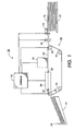
- Fig. 1 illustrates a schematic view of an exemplary embodiment of a conventional ink jet printer 10.
- the ink jet printer 10 includes an input tray 12 containing cut sheets 14 of paper stock to be printed upon by the ink jet printer 10. Single sheets 14 of paper are removed from the input tray 12 by one or more pick-up rollers 16 and fed by one or more feed rollers 18 to a paper transport mechanism 20.
- the paper transport mechanism 20 moves the sheet 14 by one or more feed belts 22 driven by rollers 24 beneath a printing member 26.
- the belts 22 are made of a material transparent to microwave power having a low dielectric constant.
- the printing member 26 includes a page-width ink jet printhead which deposits ink on the sheet 14 as the sheet moves past the printhead.
- the page-width ink jet printhead is a linear array of print nozzles as wide as the sheet so that ink is deposited across the entire width of a sheet.
- This invention is equally applicable, however, to printers having an ink jet printhead which moves across the sheet 14 periodically, in swaths, to form the image, much like a typewriter.
- the print member 26 includes an ink supply and the necessary electronics to control the deposition of ink on the page.
- the ink that is used is formulated to be heatable using microwave power.
- Such ink may include compounds designed to couple with the microwave power for increasing the amount of heat introduced into the ink by the microwaves.
- One such compound is an ionic compound at least partially ionizable in the liquid vehicle.
- U.S. Patent 5,220,346 discloses a suitable ink and is incorporated herein by reference in its entirety.
- the sheet 14 is carried by the paper transport mechanism 20, immediately after printing or within about 5 seconds or less, to a microwave dryer 28.
- the sheet 14 enters an input slot 30 and exits an output slot 32.
- a transport mechanism such as one using a vacuum applied to the bottom side of the paper or one using a static mat, carries the paper through the microwave dryer 28.
- microwave power is delivered to the sheet 14 to dry the ink deposited on the sheet 14. Once the sheet 14 is substantially dry, the sheet is sent to an output tray 34.
- a controller 36 controls the printing member 26, the microwave dryer 28, and the paper transport mechanism 20 as outlined above
- an adaptive dryer control can also be used.
- U.S. Patent 5,214,442 discloses such an adaptive dryer control and is incorporated herein by reference in its entirety.
- the microwave dryer 28 has such a fast drying rate that the excess liquid in the ink on the substrate is evaporated from the surface of the printed sheet before any appreciable absorption occurs. Additionally, microwave power generated in the microwave dryer 28 produces an electromagnetic field sufficiently powerful to effectively dry a thin layer of ink on the sheet 14.
- Fig. 2 illustrates schematic view of an exemplary embodiment of an ink jet printer incorporating a first exemplary embodiment of a metal detection and damage avoidance system according to this invention.
- a metal detector 100 is placed between the one or more pick-up rollers 16 and the one or more feed rollers 18.
- the metal detector 100 may be designed to detect one or more articles made of iron, such as staples, paper clips or metallic letterheads. This metal detector 100 detects the magnetic properties of the iron-containing articles, and is very well known.
- Various exemplary embodiments of a metal detector 100 embody a coil that produces a magnetic field. Any modification of that field by the entry of an iron-containing article is detected and used to control the output of the metal detector.
- Another metal detector 100 uses alternating current to produce a magnetic field. When a metal object enters the field, eddy currents are induced in the object. These eddy currents create a counter magnetic field, which alters the net magnetic field sensed by a magnetic field sensor.
- the metal detector 100 sends a signal to the controller 36.
- the controller 36 stops the one or more pick-up rollers 16 and the one or more feed rollers 18 and displays a message to the user indicating that the jam is due to metal detected on the stopped sheet.
- the sheet can then be removed to a purged output. Once the sheet is removed, the metal detector no longer detects the metal. Thus, the signal to the controller 36 is removed. As a result, the controller allows printing to resume.
- Fig. 3 is a schematic view of an exemplary embodiment of an ink jet printer incorporating a second exemplary embodiment of the metal detection and damage avoidance system according to this invention.
- a metal detector 100 is placed outside the microwave dryer 28 immediately prior to the input portion or slot 30.
- the metal detector 100 detects metal
- the metal detector sends a signal to the controller 36.
- the controller 36 shuts off power to the microwave dryer 28.
- the controller 36 uses the speed of the belt 22 to determine when the metal detected by the metal detector 100 has exited the microwave dryer 28.
- the controller 36 restores power to the microwave dryer 28 when the last metal detected by the metal detector 100 has had time to exit the microwave dryer 28.
- Fig. 4 is a schematic view of an exemplary embodiment of an ink jet printer incorporating a third embodiment of the metal detection and damage avoidance system according to this invention.
- a first metal detector 100 is placed outside the microwave dryer 28 immediately prior to the input portion or slot 30.
- a second metal detector 102 is placed outside the microwave dryer 28 immediately after the output portion or slot 32.
- the first metal detector 100 senses metal
- the first metal detector 100 sends a signal to the controller 36 for as long as the first metal detector 100 senses metal.
- the controller 36 shuts off power to the microwave dryer 28.
- the second metal detector 102 detects metal
- the second metal detector 102 sends a second signal to the controller 36.
- the controller 36 restores power to the microwave dryer 28.
- the controller 36 restores power when the last element of the metal detected and set by the first metal detector 100 is detected by the second metal detector 102, based on the first and second signals output by the first and second metal detectors 100 and 102.
Landscapes
- Health & Medical Sciences (AREA)
- General Health & Medical Sciences (AREA)
- Toxicology (AREA)
- Ink Jet (AREA)
- Drying Of Solid Materials (AREA)
Abstract
Description
- The invention relates to fluid ejection systems that use microwave dryers.
- A fluid ejection system, such as an ink jet printer, typically has at least one printhead from which droplets of fluid are directed towards a recording medium or recording sheet. Within the printhead, the fluid is contained in a plurality of channels. Droplets of the fluid are expelled as required from orifices or nozzles located at the end of the channels.
- A fluid ejector head may be incorporated into either a carriage type fluid ejection system, a page-width type fluid ejection system, or a combination of the two. The carriage type fluid ejection system typically has a relatively small fluid ejector head containing the fluid channels and nozzles. The fluid ejector head is often sealingly attached to a disposable fluid supply cartridge. The combined fluid ejector head and cartridge assembly is attached to a carriage, which is reciprocated to eject fluid according to one swath of information at a time on a receiving medium. After the swath is formed, the receiving medium is stepped a distance equal to the height of the swath, or a portion of the swath, so that the next swath overlaps or is contiguous with the previous swath. The procedure is repeated until all of the information has been used. In contrast, the page-width fluid ejection system includes a fluid ejector head having a length sufficiently long to eject fluid across the width or length of the receiving medium. The receiving medium is continually moved past the page-width fluid ejector head in a direction normal to the length of the fluid ejector head and at a constant or varying speed during the fluid ejection process.
- Many fluids, particularly those used in ink jet printing, include a colorant and a liquid. Some fluids also include a low vapor pressure solvent. When fluid is ejected onto the receiving medium, the individual spots of fluid deposited on the receiving medium form a desired pattern. Once deposited, the liquid is removed from the fluid to leave a desired residue.
- Liquid can be removed from the fluid and the receiving medium by a number of methods. One simple method is natural air drying, in which the liquid component of the fluid deposited on the receiving medium is allowed to evaporate without mechanical assistance. A significant amount of fluid is diffused and absorbed into the receiving medium when this method is used. In high-speed page-width fluid ejection systems, drying is usually achieved by transporting the receiving media through a microwave dryer to evaporate the liquid from the fluid.
- Microwave dryers are particularly efficient for drying fluid on receiving media in high speed thermal ink jet printing. However, introducing foreign metallic materials, such as, for example, staples, paper clips, decorative metallic leaf on letterhead and the like, into a microwave dryer cavity can have damaging consequences when the dryer is generating electromagnetic waves. Any metal entering the microwave dryer cavity under these conditions will immediately couple microwave power. This causes the metal to heat up dramatically and to arc and possibly damage the microwave dryer. Receiving media and transport belts in close proximity to the metal and the arc will rapidly heat up and deform. Damage to transport belts can affect the output quality of the fluid receiving medium, affect the reliability of the entire fluid ejection system and frustrate the user. Further, electromagnetic coupling results in electromagnetic radiation from the cavity of the microwave dryer which is a safety hazard. Preventing this problematic scenario requires assuring that foreign metallic materials cannot enter the microwave dryer cavity when microwave RF power is applied.
- This invention provides systems and methods that detect metallic materials during feeding recording media to the ejection area of the fluid ejection system.
- This invention separately provides systems and methods that reduce damage to a microwave dryer by stopping feeding operations upon detecting offending materials and allowing the removal of the offending materials.
- This invention separately provides systems and methods that detect metallic materials prior to entry of such metallic materials into a microwave dryer.
- This invention additionally provides systems and methods that reduce damage by turning off microwave power when metallic materials are detected in this manner.
- This invention separately provides systems arid methods that detect metallic materials after the offending materials exit from a microwave dryer and to turn on microwave power after the metallic materials exit the microwave dryer cavity.
- These and other features and advantages of this invention are described in, or are apparent from, the following detailed description of various exemplary embodiments of the systems and methods according to this invention.
- Various embodiments of this invention will be described in detail, with reference to the following figures, wherein:
- Fig. 1 is a schematic view of an exemplary embodiment of a conventional ink jet printer suitable for use with the this invention.
- Fig. 2 is a schematic view of an exemplary embodiment of the printing portion of an ink jet printer incorporating a first exemplary embodiment of the detection and control system according to the invention.
- Fig. 3 is a schematic view of an exemplary embodiment of the printing portion of an ink jet printer incorporating a second exemplary embodiment of the detection and control system according to the invention.
- Fig. 4 is a schematic view of an exemplary embodiment of the printing portion of an ink jet printer incorporating a third exemplary embodiment of the detection and control system according to the invention.
-
- The following detailed description of variou exemplary embodiments of the fluid ejection systems according to this invention are directed to one specific type of fluid ejection system, an ink jet printer, for sake of clarity and familiarity. However, it should be appreciated that the principles of this invention, as outlined and/or discussed below, can be equally applied to any known or later developed fluid ejection systems, beyond the ink jet printer specifically discussed herein.
- Fig. 1 illustrates a schematic view of an exemplary embodiment of a conventional
ink jet printer 10. Theink jet printer 10 includes aninput tray 12 containingcut sheets 14 of paper stock to be printed upon by theink jet printer 10.Single sheets 14 of paper are removed from theinput tray 12 by one or more pick-up rollers 16 and fed by one ormore feed rollers 18 to apaper transport mechanism 20. Thepaper transport mechanism 20 moves thesheet 14 by one ormore feed belts 22 driven byrollers 24 beneath aprinting member 26. Thebelts 22 are made of a material transparent to microwave power having a low dielectric constant. Theprinting member 26 includes a page-width ink jet printhead which deposits ink on thesheet 14 as the sheet moves past the printhead. The page-width ink jet printhead is a linear array of print nozzles as wide as the sheet so that ink is deposited across the entire width of a sheet. This invention is equally applicable, however, to printers having an ink jet printhead which moves across thesheet 14 periodically, in swaths, to form the image, much like a typewriter. Theprint member 26 includes an ink supply and the necessary electronics to control the deposition of ink on the page. - In various exemplary embodiments, the ink that is used is formulated to be heatable using microwave power. Such ink may include compounds designed to couple with the microwave power for increasing the amount of heat introduced into the ink by the microwaves. One such compound is an ionic compound at least partially ionizable in the liquid vehicle. U.S. Patent 5,220,346 discloses a suitable ink and is incorporated herein by reference in its entirety.
- Once the
sheet 14 has been printed, thesheet 14 is carried by thepaper transport mechanism 20, immediately after printing or within about 5 seconds or less, to amicrowave dryer 28. Thesheet 14 enters aninput slot 30 and exits anoutput slot 32. A transport mechanism, such as one using a vacuum applied to the bottom side of the paper or one using a static mat, carries the paper through themicrowave dryer 28. As thesheet 14 passes through themicrowave dryer 28, microwave power is delivered to thesheet 14 to dry the ink deposited on thesheet 14. Once thesheet 14 is substantially dry, the sheet is sent to anoutput tray 34. - A
controller 36 controls theprinting member 26, themicrowave dryer 28, and thepaper transport mechanism 20 as outlined above In addition, an adaptive dryer control can also be used. U.S. Patent 5,214,442 discloses such an adaptive dryer control and is incorporated herein by reference in its entirety. - The
microwave dryer 28 has such a fast drying rate that the excess liquid in the ink on the substrate is evaporated from the surface of the printed sheet before any appreciable absorption occurs. Additionally, microwave power generated in themicrowave dryer 28 produces an electromagnetic field sufficiently powerful to effectively dry a thin layer of ink on thesheet 14. - Fig. 2 illustrates schematic view of an exemplary embodiment of an ink jet printer incorporating a first exemplary embodiment of a metal detection and damage avoidance system according to this invention. In this first exemplary embodiment, a
metal detector 100 is placed between the one or more pick-uprollers 16 and the one ormore feed rollers 18. Themetal detector 100 may be designed to detect one or more articles made of iron, such as staples, paper clips or metallic letterheads. Thismetal detector 100 detects the magnetic properties of the iron-containing articles, and is very well known. Various exemplary embodiments of ametal detector 100 embody a coil that produces a magnetic field. Any modification of that field by the entry of an iron-containing article is detected and used to control the output of the metal detector. - Another
metal detector 100 uses alternating current to produce a magnetic field. When a metal object enters the field, eddy currents are induced in the object. These eddy currents create a counter magnetic field, which alters the net magnetic field sensed by a magnetic field sensor. - These principles of metal detection are disclosed in U.S. Patents 4,354,178 and 2,179,240. Both ferrous and non-ferrous metals may be detected, as demonstrated in the 178 patent.
- When metal is detected, the
metal detector 100 sends a signal to thecontroller 36. In response, thecontroller 36 stops the one or more pick-uprollers 16 and the one ormore feed rollers 18 and displays a message to the user indicating that the jam is due to metal detected on the stopped sheet. The sheet can then be removed to a purged output. Once the sheet is removed, the metal detector no longer detects the metal. Thus, the signal to thecontroller 36 is removed. As a result, the controller allows printing to resume. - Fig. 3 is a schematic view of an exemplary embodiment of an ink jet printer incorporating a second exemplary embodiment of the metal detection and damage avoidance system according to this invention. In this embodiment, a
metal detector 100 is placed outside themicrowave dryer 28 immediately prior to the input portion orslot 30. When themetal detector 100 detects metal, the metal detector sends a signal to thecontroller 36. In response, thecontroller 36 shuts off power to themicrowave dryer 28. In this embodiment, thecontroller 36 uses the speed of thebelt 22 to determine when the metal detected by themetal detector 100 has exited themicrowave dryer 28. Thecontroller 36 restores power to themicrowave dryer 28 when the last metal detected by themetal detector 100 has had time to exit themicrowave dryer 28. - Fig. 4 is a schematic view of an exemplary embodiment of an ink jet printer incorporating a third embodiment of the metal detection and damage avoidance system according to this invention. In this third embodiment of the metal detection and damage avoidance system, a
first metal detector 100 is placed outside themicrowave dryer 28 immediately prior to the input portion orslot 30. Asecond metal detector 102 is placed outside themicrowave dryer 28 immediately after the output portion orslot 32. When thefirst metal detector 100 senses metal, thefirst metal detector 100 sends a signal to thecontroller 36 for as long as thefirst metal detector 100 senses metal. In response, thecontroller 36 shuts off power to themicrowave dryer 28. When thesecond metal detector 102 detects metal, thesecond metal detector 102 sends a second signal to thecontroller 36. In response, thecontroller 36 restores power to themicrowave dryer 28. Thecontroller 36 restores power when the last element of the metal detected and set by thefirst metal detector 100 is detected by thesecond metal detector 102, based on the first and second signals output by the first andsecond metal detectors
Claims (6)
- A fluid ejection system, comprising:a metal detector placed within a metal detection range of a transport system and between a pick-up roller and an inlet slot of a microwave dryer; anda controller that stops the pick-up roller in response to a signal from the metal detector indicating metal has been detected.
- A fluid ejection system, comprising:a metal detector placed near an input slot of a microwave dryer and within a metal detection range of a transport system for a recording medium; anda controller that shuts off power to the microwave dryer in response to receiving an output from the metal detector indicating metal has been detected and that restores power when a last metal object detected by the metal detector has exited the microwave dryer, the time of exit determined based on a speed of the transport system.
- A fluid ejection system, comprising:a first metal detector placed near an input slot of a microwave dryer and within a first metal detection range of a transport system;a second metal detector placed near an output slot of the microwave dryer and within a second metal detection range of the transport system; anda controller that shuts off power to the microwave dryer in response to a signal from the first metal detector indicating metal has been detected and that restores power to the microwave dryer in response to a signal from the second metal detector indicating that a last metal object detected by the first metal detector has been detected by the second metal detector.
- A method for reducing damage to a microwave dryer of a fluid ejection system due to the presence of metal in a microwave drying cavity, comprising:transporting a fluid receiving medium within a metal detection range of a metal detector placed between a pick-up roller and an inlet slot of the microwave dryer; andstopping transporting the fluid receiving medium in response to a signal from the metal detector indicating metal has been detected.
- A method for reducing damage to a microwave dryer of a fluid ejection system due to the presence of metal in a microwave drying cavity, comprising:transporting a fluid receiving medium within a metal detection range of a first metal detector placed near an input slot of the microwave dryer and a second metal detector placed near an output slot of the microwave dryer; andstopping the microwave dryer from generating an electromagnetic field in response to a signal from the first metal detector indicating that metal has been detected; andoperating the microwave dryer to resume generating the electromagnetic field in response to a signal from the second metal detector indicating that a last metal object detected by the first metal detector has been detected by the second metal detector.
- A method for reducing damage to a microwave dryer of a fluid ejection system due to the presence of metal in a microwave drying cavity, comprising:transporting a fluid receiving medium within a metal detection range of a metal detector placed near an input slot to the microwave dryer;stopping the microwave dryer from generating an electromagnetic field in response to a signal from the metal detector indicating metal has been detected; andoperating the microwave dryer to resume generating the electromagnetic field after a determined time interval, the time interval determined based on a transport speed of the fluid receiving medium through the microwave dryer.
Applications Claiming Priority (2)
| Application Number | Priority Date | Filing Date | Title |
|---|---|---|---|
| US771553 | 1991-10-08 | ||
| US09/771,553 US6409329B1 (en) | 2001-01-30 | 2001-01-30 | Method and device to prevent foreign metallic object damage in fluid ejection systems using microwave dryers |
Publications (2)
| Publication Number | Publication Date |
|---|---|
| EP1228884A1 true EP1228884A1 (en) | 2002-08-07 |
| EP1228884B1 EP1228884B1 (en) | 2005-04-20 |
Family
ID=25092196
Family Applications (1)
| Application Number | Title | Priority Date | Filing Date |
|---|---|---|---|
| EP02001516A Expired - Lifetime EP1228884B1 (en) | 2001-01-30 | 2002-01-22 | Method and device to prevent foreign metallic object damage in fluid ejection systems using microwave dryers |
Country Status (4)
| Country | Link |
|---|---|
| US (1) | US6409329B1 (en) |
| EP (1) | EP1228884B1 (en) |
| JP (1) | JP2002254618A (en) |
| DE (1) | DE60203747T2 (en) |
Families Citing this family (11)
| Publication number | Priority date | Publication date | Assignee | Title |
|---|---|---|---|---|
| US6663239B2 (en) * | 2001-10-31 | 2003-12-16 | Hewlett-Packard Development Company, L.P. | Microwave applicator for inkjet printer |
| CZ20024272A3 (en) * | 2002-12-30 | 2004-03-17 | Ústav chemických procesů Akademie věd ČR | Method and apparatus for drying books and similar paper-based material |
| JP4371063B2 (en) * | 2005-02-18 | 2009-11-25 | 富士ゼロックス株式会社 | Magnetic body detection apparatus and method |
| US7556265B1 (en) * | 2006-05-12 | 2009-07-07 | Unisys Corporation | Document processing system with mechanism for detecting staples, paper clips, and like foreign items |
| US8182552B2 (en) | 2006-12-28 | 2012-05-22 | Kimberly-Clark Worldwide, Inc. | Process for dyeing a textile web |
| US7568251B2 (en) | 2006-12-28 | 2009-08-04 | Kimberly-Clark Worldwide, Inc. | Process for dyeing a textile web |
| US20080156427A1 (en) * | 2006-12-28 | 2008-07-03 | Kimberly-Clark Worldwide, Inc. | Process For Bonding Substrates With Improved Microwave Absorbing Compositions |
| US7740666B2 (en) | 2006-12-28 | 2010-06-22 | Kimberly-Clark Worldwide, Inc. | Process for dyeing a textile web |
| US7674300B2 (en) * | 2006-12-28 | 2010-03-09 | Kimberly-Clark Worldwide, Inc. | Process for dyeing a textile web |
| US8632613B2 (en) | 2007-12-27 | 2014-01-21 | Kimberly-Clark Worldwide, Inc. | Process for applying one or more treatment agents to a textile web |
| JP5870239B2 (en) * | 2012-03-09 | 2016-02-24 | パナソニックIpマネジメント株式会社 | High frequency heating device |
Citations (2)
| Publication number | Priority date | Publication date | Assignee | Title |
|---|---|---|---|---|
| US5570118A (en) * | 1992-11-12 | 1996-10-29 | Xerox Corporation | Color ink-jet printing with fast-and-slow-drying inks |
| US5579693A (en) * | 1994-12-12 | 1996-12-03 | Xerox Corporation | Curl control of printed sheets |
Family Cites Families (4)
| Publication number | Priority date | Publication date | Assignee | Title |
|---|---|---|---|---|
| US5318229A (en) | 1992-11-18 | 1994-06-07 | Brown John D | Protective device for paper shredders |
| US6155669A (en) * | 1998-01-08 | 2000-12-05 | Xerox Corporation | Pagewidth ink jet printer including a printbar mounted encoding system |
| US6089702A (en) * | 1999-01-19 | 2000-07-18 | Xerox Corporation | Method and apparatus for degassing ink utilizing microwaves |
| US6293649B1 (en) * | 1999-04-30 | 2001-09-25 | Hewlett-Packard Company | Print cartridge latching mechanism for a displaceable print cartridge chute |
-
2001
- 2001-01-30 US US09/771,553 patent/US6409329B1/en not_active Expired - Lifetime
-
2002
- 2002-01-22 EP EP02001516A patent/EP1228884B1/en not_active Expired - Lifetime
- 2002-01-22 DE DE60203747T patent/DE60203747T2/en not_active Expired - Lifetime
- 2002-01-23 JP JP2002013729A patent/JP2002254618A/en active Pending
Patent Citations (2)
| Publication number | Priority date | Publication date | Assignee | Title |
|---|---|---|---|---|
| US5570118A (en) * | 1992-11-12 | 1996-10-29 | Xerox Corporation | Color ink-jet printing with fast-and-slow-drying inks |
| US5579693A (en) * | 1994-12-12 | 1996-12-03 | Xerox Corporation | Curl control of printed sheets |
Also Published As
| Publication number | Publication date |
|---|---|
| US6409329B1 (en) | 2002-06-25 |
| JP2002254618A (en) | 2002-09-11 |
| DE60203747T2 (en) | 2005-09-22 |
| EP1228884B1 (en) | 2005-04-20 |
| DE60203747D1 (en) | 2005-05-25 |
Similar Documents
| Publication | Publication Date | Title |
|---|---|---|
| EP0423820B1 (en) | Ink jet printer | |
| US6409329B1 (en) | Method and device to prevent foreign metallic object damage in fluid ejection systems using microwave dryers | |
| US5291227A (en) | Ink jet printer having improved paper transport mechanism | |
| HK61197A (en) | Airflow system for thermal ink-jet printer | |
| US5579693A (en) | Curl control of printed sheets | |
| JP2009233857A (en) | Recorder, target transport device, and target transport method | |
| US6582072B1 (en) | Linefeed control in belt-type printers | |
| US20020057321A1 (en) | Inkjet printing media handling system with advancing guide shim | |
| JP2000272110A (en) | INK JET PRINTING APPARATUS AND DISCHARGE RECOVERY METHOD OF INK JET PRINTING APPARATUS | |
| US20160121631A1 (en) | Printhead Protection Device For Direct-To-Paper Continuous-Feed Inkjet Printer | |
| JP6676348B2 (en) | Ink printing equipment and method of operating ink printing equipment | |
| GB2320913A (en) | Inkjet printer with paper width detection by sensors mounted on sheet supports and printhead carriage | |
| JPS61127369A (en) | Print issuer for slip or account book | |
| JPH05345456A (en) | Recording device | |
| KR20040067342A (en) | Ink-jet printer | |
| JPH11348313A5 (en) | ||
| US20150009266A1 (en) | Ink cartridge and ink jet printer | |
| EP0997301A2 (en) | Infrared foil heater for drying ink jet images on a recording medium | |
| JP2017222096A (en) | Image forming apparatus | |
| JP2007130930A (en) | Recording device | |
| JP2927365B2 (en) | Fixing device and image recording apparatus using the fixing device | |
| JP5311753B2 (en) | Image forming apparatus | |
| GB2211471A (en) | Hot-melt type ink jet recording apparatus | |
| JPH06297798A (en) | Paper guide device for printer | |
| JP3554003B2 (en) | Ink jet recording device |
Legal Events
| Date | Code | Title | Description |
|---|---|---|---|
| PUAI | Public reference made under article 153(3) epc to a published international application that has entered the european phase |
Free format text: ORIGINAL CODE: 0009012 |
|
| AK | Designated contracting states |
Kind code of ref document: A1 Designated state(s): AT BE CH CY DE DK ES FI FR GB GR IE IT LI LU MC NL PT SE TR |
|
| AX | Request for extension of the european patent |
Free format text: AL;LT;LV;MK;RO;SI |
|
| 17P | Request for examination filed |
Effective date: 20030207 |
|
| AKX | Designation fees paid |
Designated state(s): DE FR GB |
|
| GRAP | Despatch of communication of intention to grant a patent |
Free format text: ORIGINAL CODE: EPIDOSNIGR1 |
|
| GRAS | Grant fee paid |
Free format text: ORIGINAL CODE: EPIDOSNIGR3 |
|
| GRAA | (expected) grant |
Free format text: ORIGINAL CODE: 0009210 |
|
| AK | Designated contracting states |
Kind code of ref document: B1 Designated state(s): DE FR GB |
|
| REG | Reference to a national code |
Ref country code: GB Ref legal event code: FG4D |
|
| REG | Reference to a national code |
Ref country code: IE Ref legal event code: FG4D |
|
| REF | Corresponds to: |
Ref document number: 60203747 Country of ref document: DE Date of ref document: 20050525 Kind code of ref document: P |
|
| ET | Fr: translation filed | ||
| PLBE | No opposition filed within time limit |
Free format text: ORIGINAL CODE: 0009261 |
|
| STAA | Information on the status of an ep patent application or granted ep patent |
Free format text: STATUS: NO OPPOSITION FILED WITHIN TIME LIMIT |
|
| 26N | No opposition filed |
Effective date: 20060123 |
|
| REG | Reference to a national code |
Ref country code: FR Ref legal event code: PLFP Year of fee payment: 15 |
|
| REG | Reference to a national code |
Ref country code: FR Ref legal event code: PLFP Year of fee payment: 16 |
|
| PGFP | Annual fee paid to national office [announced via postgrant information from national office to epo] |
Ref country code: GB Payment date: 20161228 Year of fee payment: 16 |
|
| PGFP | Annual fee paid to national office [announced via postgrant information from national office to epo] |
Ref country code: FR Payment date: 20161221 Year of fee payment: 16 |
|
| PGFP | Annual fee paid to national office [announced via postgrant information from national office to epo] |
Ref country code: DE Payment date: 20161219 Year of fee payment: 16 |
|
| REG | Reference to a national code |
Ref country code: DE Ref legal event code: R119 Ref document number: 60203747 Country of ref document: DE |
|
| GBPC | Gb: european patent ceased through non-payment of renewal fee |
Effective date: 20180122 |
|
| PG25 | Lapsed in a contracting state [announced via postgrant information from national office to epo] |
Ref country code: FR Free format text: LAPSE BECAUSE OF NON-PAYMENT OF DUE FEES Effective date: 20180131 Ref country code: DE Free format text: LAPSE BECAUSE OF NON-PAYMENT OF DUE FEES Effective date: 20180801 |
|
| REG | Reference to a national code |
Ref country code: FR Ref legal event code: ST Effective date: 20180928 |
|
| PG25 | Lapsed in a contracting state [announced via postgrant information from national office to epo] |
Ref country code: GB Free format text: LAPSE BECAUSE OF NON-PAYMENT OF DUE FEES Effective date: 20180122 |