EP1228842A1 - Robot and method of controlling the robot - Google Patents
Robot and method of controlling the robot Download PDFInfo
- Publication number
- EP1228842A1 EP1228842A1 EP00970142A EP00970142A EP1228842A1 EP 1228842 A1 EP1228842 A1 EP 1228842A1 EP 00970142 A EP00970142 A EP 00970142A EP 00970142 A EP00970142 A EP 00970142A EP 1228842 A1 EP1228842 A1 EP 1228842A1
- Authority
- EP
- European Patent Office
- Prior art keywords
- robot
- speed reducer
- reduction ratio
- load
- motor
- Prior art date
- Legal status (The legal status is an assumption and is not a legal conclusion. Google has not performed a legal analysis and makes no representation as to the accuracy of the status listed.)
- Withdrawn
Links
Images

Classifications
-
- B—PERFORMING OPERATIONS; TRANSPORTING
- B25—HAND TOOLS; PORTABLE POWER-DRIVEN TOOLS; MANIPULATORS
- B25J—MANIPULATORS; CHAMBERS PROVIDED WITH MANIPULATION DEVICES
- B25J9/00—Program-controlled manipulators
- B25J9/16—Program controls
- B25J9/1628—Program controls characterised by the control loop
- B25J9/1638—Program controls characterised by the control loop compensation for arm bending/inertia, pay load weight/inertia
-
- B—PERFORMING OPERATIONS; TRANSPORTING
- B25—HAND TOOLS; PORTABLE POWER-DRIVEN TOOLS; MANIPULATORS
- B25J—MANIPULATORS; CHAMBERS PROVIDED WITH MANIPULATION DEVICES
- B25J9/00—Program-controlled manipulators
- B25J9/10—Program-controlled manipulators characterised by positioning means for manipulator elements
- B25J9/102—Gears specially adapted therefor, e.g. reduction gears
-
- Y—GENERAL TAGGING OF NEW TECHNOLOGICAL DEVELOPMENTS; GENERAL TAGGING OF CROSS-SECTIONAL TECHNOLOGIES SPANNING OVER SEVERAL SECTIONS OF THE IPC; TECHNICAL SUBJECTS COVERED BY FORMER USPC CROSS-REFERENCE ART COLLECTIONS [XRACs] AND DIGESTS
- Y10—TECHNICAL SUBJECTS COVERED BY FORMER USPC
- Y10S—TECHNICAL SUBJECTS COVERED BY FORMER USPC CROSS-REFERENCE ART COLLECTIONS [XRACs] AND DIGESTS
- Y10S700/00—Data processing: generic control systems or specific applications
- Y10S700/90—Special robot structural element
Definitions
- the present invention relates to a robot that is driven by a motor via a speed reducer, and in particular, a vertical multi-joint robot.
- a speed reducer intervenes between a robot and a servomotor.
- a cyclone speed reducer and a harmonic speed reducer are adopted as such a speed reducer, the reduction ratio is fixed in either case, and the output of the servo motor is reduced at a constant reduction ratio.
- an electric robot is disclosed by Japanese Unexamined Patent Publication No. Sho-64-51285, which is provided with means for varying the reduction ratio between a joint mechanism and the speed reducer.
- the reduction ratio is changed in teaching and in playback operations, wherein the reduction ratio in the playback operation is fixed at a constant value.
- a reduction ratio suited to such a maximum load is determined on the basis of a load status applied to the servomotor is maximized with the design maximum load mass attached onto the robot, that is, a status where the rotational inertia is maximized when the arm is swung extremely outside in the case of swinging on the horizontal surface, and a status where a moment resulting from gravity with the arm horizontally shifted down in the case of swinging of a forward and backward swinging axis.
- a robot according to the first aspect of the invention which is driven by a motor via a speed reducer, is featured in that the above-described speed reducer is made into a speed-varying reducer whose reduction ratio is varied during a playback operation of the above-described robot.
- the robot according to the second aspect of the invention is featured in that the reduction ratio of the above-described speed reducer is varied in response to the degree of angle of the arm of the robot.
- the robot according to the third aspect of the invention is featured in that the reduction ratio of the above-described speed reducer is varied in response to the size of a load mass attached to the tip end of the arm of the above-described robot.
- the robot according to the fourth aspect of the invention is featured in that the reduction ratio of the above-described speed reducer is varied in response to the intensity of a rotational inertia around the drive shaft of the above-described robot. Also, the robot according to the fifth aspect of the invention is featured in that the reduction ratio of the above-described speed reducer is varied in response to the intensity of a moment resulting from gravity around the drive shaft of the above-described robot.
- the robot according to the sixth aspect of the invention is featured in that the robot is taught appointed operation courses to acquire fluctuations in the load of a motor by actually operating the above-described robot in compliance with the above-described operating courses, and a schedule for varying the above-described reduction ratio is determined in response to the fluctuations of the load of the above-described motor.
- the robot according to the seventh aspect of the invention is featured in that the above-described robot is taught appointed operation courses by an off-line teaching device to acquire fluctuations in the load of the motor on the basis of the above-described operation courses by simulation brought about by the above-described off-line teaching device, and a schedule for varying the reduction ratio of the above-described speed reducer is determined in compliance with the fluctuations in the load of the above-described motor.
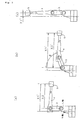
- Fig. 1 is a conceptual view of a vertical multi-joint robot showing an embodiment of the invention
- Figs. 2 are views describing a vertical multi-point robot showing the embodiment of the invention, wherein (a) shows a status where the lower arm 3 is erected and the upper arm 4 is made horizontal, (b) shows a status where the lower arm 3 is shifted down forward from the erected status by an angle ⁇ , and (c) shows a status where both the lower arm 3 and the upper arm 4 are erected.
- Fig. 1 is a conceptual view of a vertical multi-joint robot showing an embodiment of the invention.
- 1 denotes a fixed base.
- a swing head 2 is attached to the fixed base 1 so as to freely swing around a swing axis (S axis).
- the lower arm 3 is attached to the upper portion of the swing head 2 so as to freely swing forward and backward around a forward and backward swinging axis (L axis).
- the upper arm 4 is attached to the upper portion of the lower arm 3 so as to freely swing around a vertical swinging axis (U axis).
- 5 denote a load mass that is attached to the tip end of the upper arm 4.
- the load mass 5 corresponds to a mass of an end effecter, which is attached to the tip end of the robot.
- the speed reducer 6, the first servomotor 7 with a speed reducer, and the second servomotor 8 with a speed reducer are provided with a mechanism by which the reduction ratio is changed over to two ratios (high and low) during playback of the robot by an instruction of a robot controlling apparatus (not illustrated).
- the mechanism for changing the reduction ratios may be selected among publicly known mechanisms, for example, a mechanism in which engagements of gears are changed, a mechanism in which two sets of planet gears are combined, and a mechanism in which engagements of pulleys are changed.
- Figs. 2 are views describing three types of statuses of the robot, wherein (a) shows a status where the lower arm 3 is erected and the upper arm 4 is made horizontal, (b) shows a status where the lower arm 3 is shifted down forward from the erected status by an angle ⁇ , and (c) shows a status where both the lower arm 3 and the upper arm 4 are erected.
- the distance from the S axis to the center of gravity of the load mass 5 is X1 in the status shown in Fig. 2(a).
- the distance becomes large to be X'1.
- the centers of gravity of the lower arm 3 and the upper arm 4 are made farther from the S axis. Therefore, in the status shown in Fig. 2(b), the rotational inertia around the S axis becomes larger than in the status shown in Fig. 2(a).
- the reduction ratio of the speed reducer 6 is varied in response to the statuses of the lower arm 3 and upper arm 4 by instructions of the robot controlling apparatus. That is, where the angles of the lower arm 3 and the upper arm 4 are in a range where the rotational inertia around the S axis exceeds an appointed value, a larger reduction ratio is selected, and in a range where the rotational inertia around the S axis becomes smaller than the appointed value, a smaller reduction ratio is selected.
- the rotational inertia around the S axis is calculated while taking the weight of the lower arm 3 and the upper arm 4 into consideration, and the reduction ratio may be selected in compliance with the size of the result.
- the reduction ratio may be selected or determined in compliance with the size of the load mass 5.
- the larger the size a robot becomes the larger the maximum mass, that is, the conveyable mass and range of movement of an attachable end effecter become.
- the maximum speed and maximum acceleration of the robot tends to become smaller.
- a large-sized robot having a larger conveyable mass in comparison with the actual mass of the end effecter is selected in order to secure a larger range of movement. In such cases, if a smaller reduction ratio in comparison with the mass of the end effecter is selected, a large-sized robot can be operated at a high speed.
- the moment of a gravity loaded onto the first servomotor with a speed reducer by the load mass 5 is thus maximized when the statuses of the lower arm 3 and upper arm 4 are horizontal, and becomes 0 when both of the statuses of the lower arm 3 and the upper arm 4 are erect.
- an instruction for varying the reduction ratio of the first servomotor 8 with a speed reducer is issued to the robot controlling apparatus in response to the angle with respect to the statuses of the lower arm 3 and the upper arm 4, that is, reference status (usually, either one of the horizontal status or erect status may be used as the reference status).
- the moment of gravity loaded onto the first servomotor 8 with a speed reducer is calculated on the basis of the statuses of the lower arm 3 and the upper arm 4, and the reduction ratio may be varied in response to the size of the result thereof.
- the reduction ratio of the second servomotor 9 with a speed reducer, which drives the upper arm 4, may be varied.
- the moment of gravity loaded onto the second servomotor 9 with a speed reducer by the load mass 5 is maximized when the status of the upper arm 4 is horizontal, and becomes 0 when the upper arm 4 is erect.
- an instruction for varying the reduction ratio of the second servomotor 9 with a speed reducer in response to the angle with respect to the status of the upper arm 4, that is, reference status (usually, either one of the horizontal status or erect status may be used as the reference) is issued to the robot controlling apparatus.
- the reduction ratio may be selected on the basis of a larger load.
- an intermediate point is defined between the beginning point and the termination point, wherein the robot may be once stopped at the intermediate point to change the reduction ratio.
- the above-described method for varying the reduction ratio is based on the statuses of the respective arms of a vertical multi-joint robot, and is based on a static force balance.
- torque resulting from interference of respective axes is generated, wherein there is a case where the load of the drive motor cannot be obtained only by the static force balance.
- Steps (1) through (5) can be repeated until the schedule for changing the reduction ratio is converged to the optimal.
- a two-stage variable speed reducer is employed, in which a large reduction ratio and a small reduction ratio can be selected in the speed reducer.
- the present invention is not limited to the two-stage variable speed reducer, wherein it is needless to say that three or more stages of the variable speed reducer may be employed or a valiable-free speed reducer may be also employed.
- the reduction ratio of the speed reducer can be optimally varied in response to a load of the respective drive shaft based on the status of the robot and the size of amass of the end effecter, power of the drive motor can be fully brought about. Therefore, there is an effect in that the robot can be operated at a high speed.
- the present invention is effective as a robot that is driven by an electric motor via a speed reducer, in particular as a vertical multi-joint robot, and as a method for controlling the same.
Landscapes
- Engineering & Computer Science (AREA)
- Robotics (AREA)
- Mechanical Engineering (AREA)
- Manipulator (AREA)
Abstract
Description
Claims (7)
- A robot driven by a motor via a speed reducer, wherein said speed reducer is made into a speed-varying reducer whose reduction ratio is varied during a playback operation of said robot.
- The robot according to Claim 1, wherein the reduction ratio of said speed reducer is varied in according to the degree of the angle of the arm of the robot.
- The robot according to Claim 1, wherein the reduction ratio of said speed reducer is varied in response to the size of a load mass attached to the tip end of the arm of said robot.
- The robot according to Claim 1, wherein the reduction ratio of said speed reducer is varied in response to the intensity of a rotational inertia around the drive shaft of said robot.
- The robot according to Claim 1, wherein the reduction ratio of said speed reducer is varied in response to the intensity of a moment resulting from gravity around the drive shaft of said robot.
- The robot according to Claim 1, wherein the robot is taught appointed operation courses to acquire fluctuations in the load of a motor by actually operating said robot in compliance with said operating courses, and a schedule for varying said reduction ratio is determined in response to the fluctuations of the load of said motor.
- The robot according Claim 1, wherein said robot is taught appointed operation courses by an off-line teaching device to acquire fluctuations in the load of the motor on the basis of said operation courses by simulation brought about by said off-line teaching device, and a schedule for varying the reduction ratio of said speed reducer is determined in compliance with the fluctuations in the load of said motor.
Applications Claiming Priority (3)
| Application Number | Priority Date | Filing Date | Title |
|---|---|---|---|
| JP30773999A JP4423719B2 (en) | 1999-10-28 | 1999-10-28 | Robot and robot control method |
| JP30773999 | 1999-10-28 | ||
| PCT/JP2000/007552 WO2001030544A1 (en) | 1999-10-28 | 2000-10-26 | Robot and method of controlling the robot |
Publications (2)
| Publication Number | Publication Date |
|---|---|
| EP1228842A1 true EP1228842A1 (en) | 2002-08-07 |
| EP1228842A4 EP1228842A4 (en) | 2010-01-20 |
Family
ID=17972691
Family Applications (1)
| Application Number | Title | Priority Date | Filing Date |
|---|---|---|---|
| EP00970142A Withdrawn EP1228842A4 (en) | 1999-10-28 | 2000-10-26 | ROBOT AND CONTROL THEREOF |
Country Status (5)
| Country | Link |
|---|---|
| US (1) | US6684128B1 (en) |
| EP (1) | EP1228842A4 (en) |
| JP (1) | JP4423719B2 (en) |
| AU (1) | AU7960500A (en) |
| WO (1) | WO2001030544A1 (en) |
Families Citing this family (22)
| Publication number | Priority date | Publication date | Assignee | Title |
|---|---|---|---|---|
| TWI273009B (en) * | 2003-01-21 | 2007-02-11 | Yaskawa Electric Corp | Speed reducer for industrial robot |
| JP3946753B2 (en) * | 2005-07-25 | 2007-07-18 | ファナック株式会社 | Robot program evaluation / correction method and robot program evaluation / correction device |
| JP4335286B2 (en) * | 2008-02-08 | 2009-09-30 | ファナック株式会社 | Robot control apparatus and robot control method having component protection function |
| US9731419B2 (en) * | 2010-08-03 | 2017-08-15 | Praxair S.T. Technology, Inc. | System and method for programming robots |
| WO2012104895A1 (en) * | 2011-01-31 | 2012-08-09 | トヨタ自動車株式会社 | Multi-joint arm robot, control method, and control program |
| CN104203505A (en) * | 2012-03-22 | 2014-12-10 | 株式会社安川电机 | Work robot and robot system |
| JP6050999B2 (en) * | 2012-09-28 | 2016-12-21 | 日本電産サンキョー株式会社 | Industrial robot |
| CN102975205B (en) * | 2012-11-08 | 2015-06-17 | 陕西科技大学 | Full-automatic hand-imitation hair-combing machine |
| JP5835254B2 (en) * | 2013-03-15 | 2015-12-24 | 株式会社安川電機 | Robot system and control method of robot system |
| JP6097174B2 (en) * | 2013-08-05 | 2017-03-15 | 株式会社東芝 | Robot controller |
| JP6418782B2 (en) * | 2014-05-16 | 2018-11-07 | キヤノン株式会社 | Robot system control method, program, recording medium, robot system, and diagnostic apparatus |
| JP2016140918A (en) * | 2015-01-29 | 2016-08-08 | 株式会社安川電機 | robot |
| JP6809964B2 (en) * | 2017-03-30 | 2021-01-06 | 株式会社ダイヘン | Control device |
| CN107471208A (en) * | 2017-08-31 | 2017-12-15 | 广州泰行智能科技有限公司 | A kind of six axis robot |
| JP6743791B2 (en) * | 2017-09-20 | 2020-08-19 | 株式会社安川電機 | Robot system and work manufacturing method |
| CN111347418B (en) * | 2018-12-24 | 2021-10-29 | 深圳市优必选科技有限公司 | Method for controlling electric control servo system, electric control servo system and robot |
| JP7028196B2 (en) * | 2019-01-15 | 2022-03-02 | オムロン株式会社 | Robot control device, robot control method, and robot control program |
| JP7257816B2 (en) * | 2019-02-26 | 2023-04-14 | 住友重機械工業株式会社 | robot control system |
| JP7175797B2 (en) * | 2019-02-28 | 2022-11-21 | 株式会社ミツバ | robot |
| KR102254041B1 (en) * | 2019-06-26 | 2021-05-21 | 한국전자기술연구원 | Apparatus and System for evaluating load reliability of robot joint drive module |
| CN114766978A (en) * | 2022-05-09 | 2022-07-22 | 北京云博仰信科技有限公司 | A cleaning robot arm and its control method |
| JP2025102271A (en) * | 2023-12-26 | 2025-07-08 | 住友重機械工業株式会社 | Control device, actuator unit and robot |
Family Cites Families (5)
| Publication number | Priority date | Publication date | Assignee | Title |
|---|---|---|---|---|
| AU3583084A (en) * | 1983-12-10 | 1985-06-13 | Aida Engineering Ltd. | Playback grinding robot |
| JPS6283549A (en) * | 1985-10-07 | 1987-04-17 | Shinpo Kogyo Kk | Friction type continuously variable transmission |
| EP0523889B1 (en) * | 1991-07-06 | 1996-12-27 | Daihen Corporation | Apparatus for controlling industrial robot to perform coordinated operation using teaching playback method and method thereof |
| JP3148810B2 (en) * | 1991-11-27 | 2001-03-26 | 本田技研工業株式会社 | Control device for legged mobile robot |
| JPH09149958A (en) * | 1995-11-29 | 1997-06-10 | Miyamae:Kk | Golf ball tester |
-
1999
- 1999-10-28 JP JP30773999A patent/JP4423719B2/en not_active Expired - Fee Related
-
2000
- 2000-10-26 US US10/110,778 patent/US6684128B1/en not_active Expired - Fee Related
- 2000-10-26 EP EP00970142A patent/EP1228842A4/en not_active Withdrawn
- 2000-10-26 WO PCT/JP2000/007552 patent/WO2001030544A1/en not_active Ceased
- 2000-10-26 AU AU79605/00A patent/AU7960500A/en not_active Abandoned
Also Published As
| Publication number | Publication date |
|---|---|
| EP1228842A4 (en) | 2010-01-20 |
| JP4423719B2 (en) | 2010-03-03 |
| US6684128B1 (en) | 2004-01-27 |
| JP2001121467A (en) | 2001-05-08 |
| WO2001030544A1 (en) | 2001-05-03 |
| AU7960500A (en) | 2001-05-08 |
Similar Documents
| Publication | Publication Date | Title |
|---|---|---|
| US6684128B1 (en) | Robot and method of controlling the robot | |
| US12350838B2 (en) | Input shaping control of a robot arm in different reference spaces | |
| EP3807732B1 (en) | Dual mode free-drive of robot arm | |
| US4775289A (en) | Statically-balanced direct-drive robot arm | |
| US9785138B2 (en) | Robot and robot controller | |
| US5214749A (en) | Dynamic control of a robot with its center of mass decoupled from an end effector by a redundant linkage | |
| Salisbury et al. | Preliminary design of a whole-arm manipulation system (WAMS) | |
| JPH0581395B2 (en) | ||
| Asada et al. | A linkage design for direct-drive robot arms | |
| US11865718B2 (en) | Working device using parallel link mechanism and control method thereof | |
| WO2002066210A1 (en) | Robot control device | |
| US5708342A (en) | Method of controlling acceleration/deceleration time constants for robot | |
| JP2001121467A5 (en) | ||
| US5553509A (en) | Three degree of freedom robotic manipulator constructed from rotary drives | |
| JP2001113489A (en) | Industrial robot | |
| RU2288091C2 (en) | Method for operating two-coordinate five-hinged manipulator | |
| JPH1153021A (en) | Acceleration / deceleration pattern generation method for industrial robots | |
| JP2637148B2 (en) | SCARA robot | |
| KR100487152B1 (en) | Multi-articulated robot | |
| JP2006159406A (en) | Robot having horizontal arm | |
| JPH0643039B2 (en) | Arm drive device for articulated robot | |
| JP3174352B2 (en) | Robot acceleration / deceleration control method and device | |
| Ming et al. | Development of a hyper dynamic manipulator utilizing joint stops | |
| JPH07295651A (en) | Acceleration and deceleration controller for robot | |
| JPS61156406A (en) | Control method of industrial robot |
Legal Events
| Date | Code | Title | Description |
|---|---|---|---|
| PUAI | Public reference made under article 153(3) epc to a published international application that has entered the european phase |
Free format text: ORIGINAL CODE: 0009012 |
|
| 17P | Request for examination filed |
Effective date: 20020425 |
|
| AK | Designated contracting states |
Kind code of ref document: A1 Designated state(s): AT BE CH CY DE DK ES FI FR GB GR IE IT LI LU MC NL PT SE |
|
| AX | Request for extension of the european patent |
Free format text: AL;LT;LV;MK;RO;SI |
|
| RBV | Designated contracting states (corrected) |
Designated state(s): AT BE CH CY DE FR GB LI SE |
|
| A4 | Supplementary search report drawn up and despatched |
Effective date: 20091221 |
|
| 17Q | First examination report despatched |
Effective date: 20100225 |
|
| STAA | Information on the status of an ep patent application or granted ep patent |
Free format text: STATUS: THE APPLICATION IS DEEMED TO BE WITHDRAWN |
|
| 18D | Application deemed to be withdrawn |
Effective date: 20120501 |