EP1228826A1 - Method and device for separating casting material from poured green sand mold - Google Patents
Method and device for separating casting material from poured green sand mold Download PDFInfo
- Publication number
- EP1228826A1 EP1228826A1 EP00946321A EP00946321A EP1228826A1 EP 1228826 A1 EP1228826 A1 EP 1228826A1 EP 00946321 A EP00946321 A EP 00946321A EP 00946321 A EP00946321 A EP 00946321A EP 1228826 A1 EP1228826 A1 EP 1228826A1
- Authority
- EP
- European Patent Office
- Prior art keywords
- greensand
- cope
- drag
- cast product
- mold
- Prior art date
- Legal status (The legal status is an assumption and is not a legal conclusion. Google has not performed a legal analysis and makes no representation as to the accuracy of the status listed.)
- Withdrawn
Links
Images






Classifications
-
- B—PERFORMING OPERATIONS; TRANSPORTING
- B22—CASTING; POWDER METALLURGY
- B22D—CASTING OF METALS; CASTING OF OTHER SUBSTANCES BY THE SAME PROCESSES OR DEVICES
- B22D29/00—Removing castings from moulds, not restricted to casting processes covered by a single main group; Removing cores; Handling ingots
- B22D29/04—Handling or stripping castings or ingots
-
- B—PERFORMING OPERATIONS; TRANSPORTING
- B22—CASTING; POWDER METALLURGY
- B22C—FOUNDRY MOULDING
- B22C5/00—Machines or devices specially designed for dressing or handling the mould material so far as specially adapted for that purpose
- B22C5/08—Machines or devices specially designed for dressing or handling the mould material so far as specially adapted for that purpose by sprinkling, cooling, or drying
- B22C5/085—Cooling or drying the sand together with the castings
-
- B—PERFORMING OPERATIONS; TRANSPORTING
- B22—CASTING; POWDER METALLURGY
- B22D—CASTING OF METALS; CASTING OF OTHER SUBSTANCES BY THE SAME PROCESSES OR DEVICES
- B22D29/00—Removing castings from moulds, not restricted to casting processes covered by a single main group; Removing cores; Handling ingots
Definitions
- This invention relates to a method and an apparatus for separating an as-cast product, without damaging it, from a greensand mold that has been filled with molten metal.
- the greensand molds In a well-known conventional method to take an as-cast product out of a greensand mold after it is filled with molten metal, the greensand molds, each of which has been provided with molten metal, are put into a rotating or vibratory drum to cause the molds themselves to collapse by using their own weight and falls or vibrations and the heat from the product cast in each mold, thereby taking the as-cast products from the molds.
- a waterish layer is formed at a portion of a greensand mold after it is filled with molten metal, near and around the as-cast product, where the temperature is higher than the remaining part of it due to the heat from the as-cast product.
- this waterish layer is called a "moisture-condensed layer.” Since this moisture-condensed layer has less strength and includes a great amount of hot moisture, the inventors have searched for a method to collapse a greensand mold just at that layer. As a result, they found a method to collapse the mold, comprising putting a greensand mold or molds in an evacuated space.
- the moisture in the moisture-condensed layer which has been heated by the as-cast product to a high temperature, begins to boil, and this boiling of the moisture at the moisture-condensed layer produces there a pressure that is greater than that at the outer surface of the greensand molds (i.e., the pressure at the evacuated space) and that is great enough to collapse the molds.
- the present invention has been conceived in view of those problems discussed in the Background Art.
- the purpose of it is to provide a method and an apparatus for taking an as-cast product from a greensand mold without damaging it.
- the apparatus for separating an as-cast product from a greensand mold is provided that can take out and then transfer the as-cast products in a sequence in which the molds are produced or filled with molten metal.
- the embodiment of the method of the present invention for separating an as-cast product from a mold that has been filled with molten metal comprises the steps of transferring at least one greensand mold of a cope and a drag that have been filled with molten metal at a casting line and an as-cast product in the at least one greensand mold (the cope or drag) from the casting line to a predetermined place; surrounding airtightly within a chamber the at least one greensand mold and the as-cast product, both located at the predetermined place; and evacuating the chamber to lower the boiling point of the moisture in the moisture-condensed layer of the at least one greensand mold, thereby boiling the moisture in the moisture-condensed layer to collapse the at least one greensand mold, thereby separating the as-cast product from the at least one greensand mold.
- the embodiment of the apparatus of the present invention for separating an as-cast product from a mold that has been filled with molten metal comprises means for transferring at least one greensand mold of a cope and a drag that have been filled with molten metal at a casting line to produce a cast product and an as-cast product in the at least one greensand mold to a predetermined place; an enclosure that airtightly surrounds the one greensand mold and the as-cast product at the predetermined place; and means connected in fluid communication with the inner chamber of the enclosure for evacuating the inner chamber to lower the boiling point of the moisture in the moisture-condensed layer of the at least one greensand mold to boil the moisture in the moisture condensed layer, thereby separating the as-cast product from the at least one greensand mold.
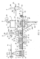
- Figs. 1-3 show the first embodiment of the present invention.
- a truck 5 runs along a casting line 6 (which extends in the direction perpendicular to the plane of the sheet of the drawing) for transferring a greensand cope 3 and a greensand drag 4 that are held in an upper flask 1 and a lower flask 2, respectively.
- the greensand cope and drag (molds) 3, 4, which have been filled with molten metal at the casting line 6, are turned upside down when necessary.
- a drive roller assembly 7 is disposed on the right of the as-casting line 6 at the same level as that of the upper surface of the truck 5.
- a first rail 8 is disposed above the casting line 6 and the drive roller assembly 7.
- a first transfer truck 10 which is provided with a first downwardly-facing cylinder 9, runs along the first rail 8.
- the piston rod 9A of the first downwardly-facing cylinder 9 has flask-supporting nails 11, 11 for engaging the flange portions of the upper and lower flasks 1, 2.
- means A for turning the cope and the drag upside down and forwarding them is disposed on the right of the drive roller assembly 7.
- the means A for turning upside down and forwarding the molds 3, 4 is configured as explained below.
- Two pairs of rollers 13, 14, which pairs are spaced in the front-and-rear directions (only one pair of rollers 13, 14 is seen in Figs. 1 and 2), are disposed on a base frame 12.
- the pairs of rollers 13, 14 receive a pair of circular frames 15, 16 such that they can rotate.
- the pair of circular frames 15, 16 are connected to each other by means of connecting frames (not shown) and constitute a revolving body 17.
- One pair of the rollers 13, 14 are drive rollers and operate to rotate the revolving body 17.
- a drive roller assembly 18 is mounted on the inner side of the revolving body 17 at the same level as that of the drive roller assembly 7.
- a drive roller assembly 19 is also mounted on the inner side of the revolving body 17 at a location above the drive roller assembly 18.
- the revolving body 17 that has been rotated through 180 degrees (i.e., it has been turned upside down) is shown, and the drive roller assembly 18 and the drive roller assembly 19 are respectively located at its upper position and lower position.
- One of the drive roller assemblies 18, 19 is operated by a drive means (not shown), which is mounted on the revolving body 17, to advance the cope 3 and drag 4 held in the upper and lower flasks 1, 2.
- the vertical spacing between the drive roller assemblies 18 and 19 is slightly greater than the total height of the matched upper and lower flasks 1, 2.
- a long, intermediate drive roller assembly 20 is disposed on the right of the means A for turning upside down and forwarding molds.
- the assembly 20 is disposed at the same level as that of the drive roller assembly 18 (in Fig. 1, at the same level as that of the drive roller assembly 19).
- a second rail 21, which runs transversely of the intermediate drive roller assembly 20, is disposed above it at a location near the means A for turning upside down and forwarding molds.
- the second rail 21, the second downwardly-facing cylinder 22, and the nails 24, 24 constitute means B for removing the lower flask.
- a lifting cylinder 25 is disposed under one side of the intermediate drive roller assembly 20 (namely, the side opposite the other side, which is located near the means A for turning upside down and forwarding the molds) under one side of the intermediate drive roller assembly 20 (namely, the side opposite the other side, which is located near the means A for turning upside down and forwarding the molds) under one side of the intermediate drive roller assembly 20 (namely, the side opposite the other side, which is located near the means A for turning upside down and forwarding the molds) a lifting cylinder 25 is disposed under one side of the intermediate drive roller assembly 20 (namely, the side opposite the other side, which is located near the means A for turning upside down and forwarding the molds) a lifting cylinder 25 is disposed under one side of the intermediate drive roller assembly 20 (namely, the side opposite the other side, which is located near the means A for turning upside down and forwarding the molds) a lifting cylinder 25 is disposed under one side of the intermediate drive roller assembly 20 (namely, the side opposite the other side, which is located near the means A for
- an enclosure 32 which is in the shape of an inverted box, is fixedly disposed above the table 29 for receiving a mold.
- the enclosure 32 is connected in fluid communication with a vacuum source (not shown) through a valve 31 and a vacuum tank 30.
- An annular or polygonal seal 33 is attached to the peripheral edge of the lower opening of the enclosure 32 for abutting and sealing the upper surface of the tray 27.
- an airtightly-enclosing means C for airtightly enclosing the greensand cope 3 held in the upper flask and the as-cast product W and means D for rapidly evacuating the chamber defined by the airtightly-enclosing means C to collapse the greensand cope 3 are arranged (the details regarding collapsing the cope will be explained below).
- a pair of intermediate operating roller assemblies 34, 34 are disposed between the intermediate drive roller assembly 20 and the enclosure 32.
- the intermediate operating roller assemblies 34, 34 extend transversely of the intermediate roller assembly 20, and the horizontal spacing between the intermediate operating roller assemblies 34 and 34 is adjustable.
- the intermediate operating roller assemblies 34, 34 constitute means E for removing the upper flask.
- a third rail 35 is disposed on the right of the enclosure 32, and a taking-out truck 38 runs along the third rail 35.
- the taking-out truck 38 is provided with a third downwardly-facing cylinder 36 that vertically moves a horizontally-rotatable swivel mechanism 37.
- the swivel mechanism 37 has a horizontal forked nail 40 connected to it through an arm 39.
- the forked nail 40 is inserted into the array of grooves of the table 29 for receiving a mold.
- the third rail 35, the taking-out truck 38, the third downwardly-facing cylinder 36, the horizontally-rotatable swivel mechanism 37, the arm 39, and the forked nail 40 constitute a means F for taking out the as-cast product from the collapsed greensand cope.
- a chute 41 is disposed under the midpoint of the intermediate drive roller assembly 20.
- the first downwardly-facing cylinder 9 then operates to slightly lift the upper and lower flasks 1, 2, which hold the greensand cope and drag 3, 4, and the first transfer truck 10 moves right to transfer the molds 3, 4 from the truck 5 to the right and put them onto the drive roller assembly 7. While transferring the molds 3, 4, the revolving body 17 of the means A for turning and forwarding molds rotates through 180 degrees from the position shown in Fig. 1, so that the drive roller assembly 18 is lowered to the level of the drive roller assembly 7.
- the drive roller assembly 7 is then operated by a drive source (not shown) to transfer the molds 3, 4 held in the upper and lower flasks 1, 2 between the drive roller assemblies 18 and 19 of the means A for turning and forwarding molds.
- the drive rollers 13, 14 of the means A for turning and forwarding molds then operates to rotate the revolving body 17 and hence the molds 3, 4 held in the flasks 1, 2 through 180 degrees.
- the drive roller assembly 19 then operates to forward the upside-down greensand drag 4 and cope 3 held in the lower and upper flasks 2, 1 to the means B for removing the lower flask.
- the second downwardly-facing cylinder 22 operates to lift the lower flask 2, which holds the greensand drag 4, by means B, to remove the lower flask 2 and the greensand drag 4 from the greensand cope 3 and the as-cast product Was shown in Fig. 1.
- the second transfer truck 23 runs to take away the removed greensand drag 4 held in the lower flask 2 to a line (not shown) for collecting the used greensand, where the greensand drag 4 is collapsed, and the collapsed greensand is collected.
- the upper flask 1 and the cope 3, which hold the as-cast product W and remain on the drive roller assembly 20, are moved by it along it to a position located between the table 29 for receiving a mold and the enclosure 32.
- the lifter cylinder 25 then operates to lift the mounting plate 26, the tray 27, the table 29 for receiving a mold, the greensand cope 3, and the as-cast product W held in the upper flask 1 until the annular seal 33 provided at the peripheral edge of the bottom opening of the enclosure 32 is pressed against the upper surface of the tray 27 such that the chamber within the enclosure 32 is made airtight by the airtightly-enclosing means C as shown in Figs. 2 and 3.
- the valve 31 of the means D for collapsing the greensand cope is opened to connect the vacuum tank 30 in fluid communication with the chamber within the enclosure 32 to rapidly evacuate the chamber.
- valve 31 is then closed, and another valve (not shown) for supplying air is opened to introduce ambient air into the chamber of the enclosure 32, while the lifter cylinder 25 operates to lower the mounting plate 26, the tray 27, the table 29 for receiving a mold, the collapsed greensand of the cope, and the as-cast product W in the position shown in Fig. 1.
- the intermediate operating roller assemblies 34, 34 which function as the means E for removing the upper flask, are moved horizontally to approach each other.
- the upper flask 1 is received by the intermediate operating roller assemblies 34, 34 and separated from the collapsed greensand of the cope and the as-cast product, and it is then transferred away by the roller assemblies 34, 34 being driven.
- the collapsed greensand of the cope and the as-cast product W remain on the table 29 for receiving a mold.
- the taking-out truck 38 of the means F for taking out the as-cast product W operates to insert the forked nail 40 into the grooves of the table 29 for receiving a mold to locate it under the as-cast product W, and the third downwardly-facing cylinder 36 then operates to slightly lift the as-cast product W with the forked nail 40, while the taking-out truck 38 moves back (to the right in Fig. 2) to take out the as-cast product W as shown in Figs. 1 and 2. From this state the horizontally rotatable mechanism 37 horizontally rotates the forked nail 40 through 180 degrees and sequentially forwards the as-cast product W for the next process.
- each cast product W is taken out without receiving any collision or impulses from any other member, i.e., all cast products W are sequentially taken out without receiving damage such as cracks, scars, and deformations, and are then forwarded for the post treatment.
- a device for upwardly drawing the cope 3 and drag 4 from the upper and lower flasks 1, 2, including a cylinder 43 for upwardly drawing the molds 3, 4 from the flasks 1, 2, is disposed between the casting line 6 and the means C for collapsing molds, which comprises the enclosure 32 and the lifter cylinder 25.
- the cope 3 and drag 4 are removed or drawn out of the upper and lower flasks 1, 2.
- the transfer truck 10 carries the upper and lower flasks 1, 2 that hold the cope 3 and the drag 4 provided with molten metal from the casting line 6 onto the base plate 45.
- the cylinder 43 for upwardly drawing molds then operates to draw the molds 3, 4 upwardly out of the flasks 1, 2 to the position shown in Fig. 4. During this upward drawing the flask stopper 47 prevents the flasks 1, 2 from being lifted.
- the horizontal pusher cylinder 49 then operates to horizontally push and forward the cope 3 and drag 4 placed on the plate 43B to the table 29 for receiving molds by way of the intermediate table 55.
- the lifter cylinder 25 then operates to lift the cope 3 and the drag 4 into the chamber within the enclosure 32 until the annular seal 33 of the enclosure 32 is pressed against the upper surface of the tray 27 (Fig. 5).
- the sealed chamber of the enclosure 32 is rapidly evacuated, and the pressure in the evacuated chamber is kept for a predetermined period of time, thereby collapsing the molds at the moisture-condensed layer 3B into pieces 3C (Fig. 6).
- the apparatus operates in the same way as in the first embodiment for the following processes.
- the table 29 for receiving molds is lowered to the level of the forked nail 40, and the forked nail 40 then takes out the as-cast product W that has just been separated from the broken pieces 3C of the greensand of the molds.
- the device upwardly draws them
- the molds may be drawn downwardly by using a similar device.
- the device may be eliminated if greensand molds are produced and drawn from the flasks by a flask-removing-type molding machine and then forwarded and filled with molten metal. In that case those molds that have no flask can be directly carried from the transfer truck 5 to the table 29 for receiving molds. It should be noted that in the flask-removing-type molding machine the molds may be drawn upwardly or downwardly out of the flasks.
- Figs. 7-10 show a modified example of the table 29 for receiving molds and the enclosure 32 of the second embodiment.
- a plurality of upwardly-facing cylinders 61 are mounted on the upper surface of the bottom of the tray 27, and the table 29 for receiving molds is secured to the distal ends of the piston rods (no reference number is given for them) of these cylinders 61.
- the table 29 for receiving molds is pointed so as to be level with the intermediate table 55.
- the pusher plate 53 (Fig. 7) pushes and forwards the cope 3 and the drag 4 to the right onto the table 29 for receiving molds.
- a plurality of first projecting bodies 59 which are fixed to the upper surface of the bottom of the tray 27, are arranged between the cylinders 61, 61 while being spaced apart a desirable distance.
- These first projecting bodies 59 each are in the shape of a rod in the example shown in Figs. 7 and 8.
- These rods 59 may be arranged to penetrate the table 29 as shown in Fig. 8 when the cylinders 61, 61 operate to lower it.
- the table 29 may be formed with throughbores through which the rods pass.
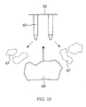
- second projecting bodies 63 which are also spaced apart a desired distance, are also mounted on the inner upper surface and inner side surfaces of the enclosure 32.
- Each of the second projecting bodies 63 may be a rod or plate with a pointed distal end.
- each of the first projecting bodies 59 is in the shape of a rod, they may be in the shape of a plate if they allow the forked nail 40 to enter under the upper surface of the table 29.
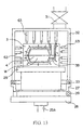
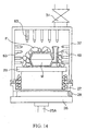
- Figs. 11-14 show a modified example of the enclosure 32 shown in the second embodiment.
- the enclosure 32 of this example is the same as the one shown in Fig. 7.
- the structure of the table 29 for receiving molds of this example is the same as the table 29 for receiving molds of the first and second embodiments.
- the piston rod 51 is retracted to the left, and the lifter cylinder 25 then operates to lift the cope 3 and the drag 4 until the annular seal 33 of the enclosure 32 is pressed against the periphery of the upper surface of the tray 27.
- the projecting bodies 63 which are mounted on the upper inner surface of the enclosure 32, are sized in length such that their distal ends contact the upper outer surface of the cope 3, while the projecting bodies 63 that are mounted on the inner side surfaces of the enclosure 32 are sized in length such that their distal ends are spaced apart from the outer side surfaces of the cope 3 or the drag 4.
- the molds 3, 4 roughly collapse at the water-condensed layer 3B as shown in Fig. 13 and further collapse into small pieces P with the aid of the projecting bodies 63 (as shown in Fig. 14).
- Figs. 15-17 show a modified example of the enclosure 32 of the second embodiment.
- the enclosure 32 of this example includes a manifold 67 disposed inside it, which has a plurality of nozzles 69. The distal ends of the nozzles 69 face the as-cast product W. Further, a pipe 71 is connected to the enclosure 32 so as to introduce the atmosphere into the manifold 67. The pipe 71 is provided with a valve 73.
- the valve 31 is opened, while the valve 3 is being closed, to rapidly evacuate the chamber of the enclosure 32, and the pressure of the evacuated chamber is kept for a predetermined period of time.
- the valve 31 is then closed, and the valve 73 is opened to introduce the atmosphere through the pipe 71 into the manifold 67.
- the atmosphere introduced into the manifold 67 is ejected from the nozzles 69 and hits the molds, which have been collapsed at the surface of the as-cast product W, to further break the collapsed molds into small pieces S of the greensand.
Landscapes
- Engineering & Computer Science (AREA)
- Mechanical Engineering (AREA)
- Casting Devices For Molds (AREA)
- Molds, Cores, And Manufacturing Methods Thereof (AREA)
Abstract
This invention provides a method and an apparatus for taking
out an as-cast product from a greensand mold that has been provided
with molten metal such that the as-cast product is not damaged.
The method of the invention is one that separates an as-cast
product from a greensand mold that has been provided with molten
metal, comprising the steps of transferring a greensand cope and
a greensand drag that have been filled with molten metal at an
casting line from the casting line to a predetermined place;
surrounding airtightly within a chamber at least either one of
the greensand cope and drag and an as-cast product in the at least
one greensand mold, both of which are located at the predetermined
place; and evacuating the chamber to lower the boiling point of
the moisture in the moisture-condensed layer of the at least one
greensand mold, to boil the moisture in the moisture-condensed
layer to collapse the at least one greensand mold, thereby
separating the as-cast product from the at least one greensand
mold.
Description
This invention relates to a method and an apparatus for
separating an as-cast product, without damaging it, from a
greensand mold that has been filled with molten metal.
In a well-known conventional method to take an as-cast
product out of a greensand mold after it is filled with molten
metal, the greensand molds, each of which has been provided with
molten metal, are put into a rotating or vibratory drum to cause
the molds themselves to collapse by using their own weight and
falls or vibrations and the heat from the product cast in each
mold, thereby taking the as-cast products from the molds.
However, to collapse a greensand mold or molds to take the
as-cast product out of them by using the above well-known
conventional method, the as-cast product is subject to strong
collisions and impulses. This results in a problem in that the
as-cast product inherently receives damage such as cracks, scars,
and deformation. Further, since as-cast products, which are to
be taken out of greensand molds that have been put into the rotating
or vibratory drum by collapsing them, are agitated in the drum
and then discharged from it, the sequence of discharging them from
the drum tends to differ from that used when they are introduced
into it. Thus the method produces a problem in that the product
history of each as-cast product cannot be known, and therefore
the most suitable treatment or process cannot be applied to it.
Generally, a waterish layer is formed at a portion of a
greensand mold after it is filled with molten metal, near and
around the as-cast product, where the temperature is higher than
the remaining part of it due to the heat from the as-cast product.
Below, this waterish layer is called a "moisture-condensed layer."
Since this moisture-condensed layer has less strength and includes
a great amount of hot moisture, the inventors have searched for
a method to collapse a greensand mold just at that layer. As a
result, they found a method to collapse the mold, comprising
putting a greensand mold or molds in an evacuated space. Since
the boiling point of the moisture in the molds becomes lower in
the evacuated space, the moisture in the moisture-condensed layer,
which has been heated by the as-cast product to a high temperature,
begins to boil, and this boiling of the moisture at the
moisture-condensed layer produces there a pressure that is greater
than that at the outer surface of the greensand molds (i.e., the
pressure at the evacuated space) and that is great enough to
collapse the molds.
The present invention has been conceived in view of those
problems discussed in the Background Art. The purpose of it is
to provide a method and an apparatus for taking an as-cast product
from a greensand mold without damaging it. According to the
embodiment of the invention, the apparatus for separating an
as-cast product from a greensand mold is provided that can take
out and then transfer the as-cast products in a sequence in which
the molds are produced or filled with molten metal.
The embodiment of the method of the present invention for
separating an as-cast product from a mold that has been filled
with molten metal comprises the steps of transferring at least
one greensand mold of a cope and a drag that have been filled with
molten metal at a casting line and an as-cast product in the at
least one greensand mold (the cope or drag) from the casting line
to a predetermined place; surrounding airtightly within a chamber
the at least one greensand mold and the as-cast product, both
located at the predetermined place; and evacuating the chamber
to lower the boiling point of the moisture in the moisture-condensed
layer of the at least one greensand mold, thereby boiling
the moisture in the moisture-condensed layer to collapse the at
least one greensand mold, thereby separating the as-cast product
from the at least one greensand mold.
The embodiment of the apparatus of the present invention
for separating an as-cast product from a mold that has been filled
with molten metal comprises means for transferring at least one
greensand mold of a cope and a drag that have been filled with
molten metal at a casting line to produce a cast product and an
as-cast product in the at least one greensand mold to a
predetermined place; an enclosure that airtightly surrounds the
one greensand mold and the as-cast product at the predetermined
place; and means connected in fluid communication with the inner
chamber of the enclosure for evacuating the inner chamber to lower
the boiling point of the moisture in the moisture-condensed layer
of the at least one greensand mold to boil the moisture in the
moisture condensed layer, thereby separating the as-cast product
from the at least one greensand mold.
Other advantages and features of the present invention will
be understood by reading about or performing the embodiments of
the invention, which will be explained below by reference to the
accompanying drawings.
The embodiments of the present invention are now explained
in detail by reference to the accompanying drawings, in which the
same reference numbers are used for the functionally same or
similar elements.
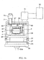
Figs. 1-3 show the first embodiment of the present invention.
In Fig. 1 a truck 5 runs along a casting line 6 (which extends
in the direction perpendicular to the plane of the sheet of the
drawing) for transferring a greensand cope 3 and a greensand drag
4 that are held in an upper flask 1 and a lower flask 2, respectively.
In this first embodiment the greensand cope and drag (molds) 3,
4, which have been filled with molten metal at the casting line
6, are turned upside down when necessary. A drive roller assembly
7 is disposed on the right of the as-casting line 6 at the same
level as that of the upper surface of the truck 5. A first rail
8 is disposed above the casting line 6 and the drive roller assembly
7. Further, a first transfer truck 10, which is provided with
a first downwardly-facing cylinder 9, runs along the first rail
8. The piston rod 9A of the first downwardly-facing cylinder 9
has flask-supporting nails 11, 11 for engaging the flange portions
of the upper and lower flasks 1, 2. Further, means A for turning
the cope and the drag upside down and forwarding them is disposed
on the right of the drive roller assembly 7.
The means A for turning upside down and forwarding the molds
3, 4 is configured as explained below. Two pairs of rollers 13,
14, which pairs are spaced in the front-and-rear directions (only
one pair of rollers 13, 14 is seen in Figs. 1 and 2), are disposed
on a base frame 12. The pairs of rollers 13, 14 receive a pair
of circular frames 15, 16 such that they can rotate. The pair
of circular frames 15, 16 are connected to each other by means
of connecting frames (not shown) and constitute a revolving body
17. One pair of the rollers 13, 14 are drive rollers and operate
to rotate the revolving body 17. A drive roller assembly 18 is
mounted on the inner side of the revolving body 17 at the same
level as that of the drive roller assembly 7. Further, a drive
roller assembly 19 is also mounted on the inner side of the
revolving body 17 at a location above the drive roller assembly
18. In Figs. 1 and 2 the revolving body 17 that has been rotated
through 180 degrees (i.e., it has been turned upside down) is shown,
and the drive roller assembly 18 and the drive roller assembly
19 are respectively located at its upper position and lower
position. One of the drive roller assemblies 18, 19 is operated
by a drive means (not shown), which is mounted on the revolving
body 17, to advance the cope 3 and drag 4 held in the upper and
lower flasks 1, 2. The vertical spacing between the drive roller
assemblies 18 and 19 is slightly greater than the total height
of the matched upper and lower flasks 1, 2.
A long, intermediate drive roller assembly 20 is disposed
on the right of the means A for turning upside down and forwarding
molds. The assembly 20 is disposed at the same level as that of
the drive roller assembly 18 (in Fig. 1, at the same level as that
of the drive roller assembly 19). A second rail 21, which runs
transversely of the intermediate drive roller assembly 20, is
disposed above it at a location near the means A for turning upside
down and forwarding molds. A second transfer truck 23, which is
provided with a second downwardly-facing cylinder 22, is mounted
on the second rail 21, and the piston rod 22A of the second
downwardly-facing cylinder 22 has nails 24, 24 for engaging with
the flanges of the lower flask 2. The second rail 21, the second
downwardly-facing cylinder 22, and the nails 24, 24 constitute
means B for removing the lower flask.
Under one side of the intermediate drive roller assembly
20 (namely, the side opposite the other side, which is located
near the means A for turning upside down and forwarding the molds)
a lifting cylinder 25 is disposed. The piston rod 25A of the lifter
cylinder 25 has at its distal end a mounting plate 26 secured to
it. A tray 27 is attached to the upper surface of the mounting
plate 26 such that it can be inclined about a connecting pin 28.
Further, a table 29 for receiving a mold thereon is secured to
the top central portion of the tray 27. The table 29 for receiving
a mold on it is formed by arranging I-beam steel members in parallel
in the forward and backward directions while defining grooves
between them.
Further, an enclosure 32, which is in the shape of an
inverted box, is fixedly disposed above the table 29 for receiving
a mold. The enclosure 32 is connected in fluid communication with
a vacuum source (not shown) through a valve 31 and a vacuum tank
30. An annular or polygonal seal 33 is attached to the peripheral
edge of the lower opening of the enclosure 32 for abutting and
sealing the upper surface of the tray 27. At this station, an
airtightly-enclosing means C for airtightly enclosing the
greensand cope 3 held in the upper flask and the as-cast product
W and means D for rapidly evacuating the chamber defined by the
airtightly-enclosing means C to collapse the greensand cope 3 are
arranged (the details regarding collapsing the cope will be
explained below). A pair of intermediate operating roller
assemblies 34, 34 are disposed between the intermediate drive
roller assembly 20 and the enclosure 32. The intermediate
operating roller assemblies 34, 34 extend transversely of the
intermediate roller assembly 20, and the horizontal spacing
between the intermediate operating roller assemblies 34 and 34
is adjustable. The intermediate operating roller assemblies 34,
34 constitute means E for removing the upper flask.
A third rail 35 is disposed on the right of the enclosure
32, and a taking-out truck 38 runs along the third rail 35. The
taking-out truck 38 is provided with a third downwardly-facing
cylinder 36 that vertically moves a horizontally-rotatable swivel
mechanism 37. The swivel mechanism 37 has a horizontal forked
nail 40 connected to it through an arm 39. The forked nail 40
is inserted into the array of grooves of the table 29 for receiving
a mold. The third rail 35, the taking-out truck 38, the third
downwardly-facing cylinder 36, the horizontally-rotatable swivel
mechanism 37, the arm 39, and the forked nail 40 constitute a means
F for taking out the as-cast product from the collapsed greensand
cope. Further, for downwardly guiding and collecting the
greensand of the collapsed mold a chute 41 is disposed under the
midpoint of the intermediate drive roller assembly 20.
In the operation of the apparatus configured as explained
above, as in Fig. 1, the flask-supporting nails 11, 11, which are
now located above the casting line 6, engage the flanges of the
upper and lower flasks 1, 2 when the cope and drag held in the
upper and lower flasks 1, 2 are carried and located in the position
under the nails 11, 11 by the truck 5 along the casting line 6
after they are filled with molten metal. The first downwardly-facing
cylinder 9 then operates to slightly lift the upper and
lower flasks 1, 2, which hold the greensand cope and drag 3, 4,
and the first transfer truck 10 moves right to transfer the molds
3, 4 from the truck 5 to the right and put them onto the drive
roller assembly 7. While transferring the molds 3, 4, the
revolving body 17 of the means A for turning and forwarding molds
rotates through 180 degrees from the position shown in Fig. 1,
so that the drive roller assembly 18 is lowered to the level of
the drive roller assembly 7.
The drive roller assembly 7 is then operated by a drive
source (not shown) to transfer the molds 3, 4 held in the upper
and lower flasks 1, 2 between the drive roller assemblies 18 and
19 of the means A for turning and forwarding molds. The drive
rollers 13, 14 of the means A for turning and forwarding molds
then operates to rotate the revolving body 17 and hence the molds
3, 4 held in the flasks 1, 2 through 180 degrees. The drive roller
assembly 19 then operates to forward the upside-down greensand
drag 4 and cope 3 held in the lower and upper flasks 2, 1 to the
means B for removing the lower flask.
Since while forwarding the greensand molds 4, 3 the flask-supporting
nails 24, 24 have been lowered, they engage the flanges
of the lower flask 2. After this engagement, the second
downwardly-facing cylinder 22 operates to lift the lower flask
2, which holds the greensand drag 4, by means B, to remove the
lower flask 2 and the greensand drag 4 from the greensand cope
3 and the as-cast product Was shown in Fig. 1. The second transfer
truck 23 runs to take away the removed greensand drag 4 held in
the lower flask 2 to a line (not shown) for collecting the used
greensand, where the greensand drag 4 is collapsed, and the
collapsed greensand is collected.
By the way, the upper flask 1 and the cope 3, which hold
the as-cast product W and remain on the drive roller assembly 20,
are moved by it along it to a position located between the table
29 for receiving a mold and the enclosure 32. The lifter cylinder
25 then operates to lift the mounting plate 26, the tray 27, the
table 29 for receiving a mold, the greensand cope 3, and the as-cast
product W held in the upper flask 1 until the annular seal 33
provided at the peripheral edge of the bottom opening of the
enclosure 32 is pressed against the upper surface of the tray 27
such that the chamber within the enclosure 32 is made airtight
by the airtightly-enclosing means C as shown in Figs. 2 and 3.
From this state the valve 31 of the means D for collapsing the
greensand cope is opened to connect the vacuum tank 30 in fluid
communication with the chamber within the enclosure 32 to rapidly
evacuate the chamber.
Further processes are explained below by reference to Figs.
2 and 3. Since when the chamber is evacuated the boiling point
of a large amount of hot moisture in the moisture-condensed layer
3A is lowered, the hot moisture boils, thereby producing a
difference in pressure between the moisture-condensed layer 3A
and the outer surface of the greensand cope 3, which is at the
low pressure of the evacuated chamber. Thus the greensand cope
3 collapses at the moisture-condensed layer 3A. The valve 31 is
then closed, and another valve (not shown) for supplying air is
opened to introduce ambient air into the chamber of the enclosure
32, while the lifter cylinder 25 operates to lower the mounting
plate 26, the tray 27, the table 29 for receiving a mold, the
collapsed greensand of the cope, and the as-cast product W in the
position shown in Fig. 1.
During that lowering of the mounting plate, etc., the
intermediate operating roller assemblies 34, 34, which function
as the means E for removing the upper flask, are moved horizontally
to approach each other. Thus the upper flask 1 is received by
the intermediate operating roller assemblies 34, 34 and separated
from the collapsed greensand of the cope and the as-cast product,
and it is then transferred away by the roller assemblies 34, 34
being driven. Meanwhile, the collapsed greensand of the cope and
the as-cast product W remain on the table 29 for receiving a mold.
The taking-out truck 38 of the means F for taking out the as-cast
product W operates to insert the forked nail 40 into the grooves
of the table 29 for receiving a mold to locate it under the as-cast
product W, and the third downwardly-facing cylinder 36 then
operates to slightly lift the as-cast product W with the forked
nail 40, while the taking-out truck 38 moves back (to the right
in Fig. 2) to take out the as-cast product W as shown in Figs.
1 and 2. From this state the horizontally rotatable mechanism
37 horizontally rotates the forked nail 40 through 180 degrees
and sequentially forwards the as-cast product W for the next
process.
Meanwhile, at the table 29 for receiving a mold from which
the as-cast product has been removed, the tray 27 is raised and
inclined relative to the connecting pin 28. Thus the collapsed
greensand on the inclined table 29 falls onto the chute 41 and
is collected at a sand process line (not shown). As is explained
above, each cast product W is taken out without receiving any
collision or impulses from any other member, i.e., all cast
products W are sequentially taken out without receiving damage
such as cracks, scars, and deformations, and are then forwarded
for the post treatment.
The second embodiment of the apparatus of the present
invention is now explained by reference to Figs. 4-6. In this
embodiment the means for turning and forwarding molds and the means
for removing the upper flask, both of which are disposed between
the casting line 6 and means D for collapsing a mold in the first
embodiment shown in Figs. 1 and 2, are not used. However, instead
of those means, a device for upwardly drawing the cope 3 and drag
4 from the upper and lower flasks 1, 2, including a cylinder 43
for upwardly drawing the molds 3, 4 from the flasks 1, 2, is
disposed between the casting line 6 and the means C for collapsing
molds, which comprises the enclosure 32 and the lifter cylinder
25. In the second embodiment, before being moved onto the table
29 for receiving molds, the cope 3 and drag 4 are removed or drawn
out of the upper and lower flasks 1, 2.
The device for upwardly drawing molds includes a cylinder
43 for upwardly drawing the molds and a base table 45 formed with
a central opening 45A, at which the cope 3 and the drag 4 held
in the upper and lower flasks 1, 2 are to be located. A flask
stopper 47 for preventing the flasks from being lifted is fixedly
disposed above the base table 45. A plate 43B is secured to the
distal end of the piston rod 43A of the cylinder 43 for upwardly
drawing molds. A horizontal pusher cylinder 49 is disposed on
the upper left of the flask stopper 47, and a pusher plate 53 is
attached to the distal end of the piston rod 51 of the pusher
cylinder 49. An intermediate table (or a plate) 55 is fixedly
disposed on the right of the flask stopper 47 and is level with
the table 29 for receiving molds (as shown in Fig. 4).
The transfer truck 10 carries the upper and lower flasks
1, 2 that hold the cope 3 and the drag 4 provided with molten metal
from the casting line 6 onto the base plate 45. The cylinder 43
for upwardly drawing molds then operates to draw the molds 3, 4
upwardly out of the flasks 1, 2 to the position shown in Fig. 4.
During this upward drawing the flask stopper 47 prevents the flasks
1, 2 from being lifted. The horizontal pusher cylinder 49 then
operates to horizontally push and forward the cope 3 and drag 4
placed on the plate 43B to the table 29 for receiving molds by
way of the intermediate table 55.
The lifter cylinder 25 then operates to lift the cope 3 and
the drag 4 into the chamber within the enclosure 32 until the
annular seal 33 of the enclosure 32 is pressed against the upper
surface of the tray 27 (Fig. 5). In the same way as in the first
embodiment, the sealed chamber of the enclosure 32 is rapidly
evacuated, and the pressure in the evacuated chamber is kept for
a predetermined period of time, thereby collapsing the molds at
the moisture-condensed layer 3B into pieces 3C (Fig. 6). The
apparatus operates in the same way as in the first embodiment for
the following processes. The table 29 for receiving molds is
lowered to the level of the forked nail 40, and the forked nail
40 then takes out the as-cast product W that has just been separated
from the broken pieces 3C of the greensand of the molds.
It should be noted that although in the above second
embodiment the device upwardly draws them, the molds may be drawn
downwardly by using a similar device.
It should also be noted that although in the above second
embodiment a device for upwardly drawing molds is used, the device
may be eliminated if greensand molds are produced and drawn from
the flasks by a flask-removing-type molding machine and then
forwarded and filled with molten metal. In that case those molds
that have no flask can be directly carried from the transfer truck
5 to the table 29 for receiving molds. It should be noted that
in the flask-removing-type molding machine the molds may be drawn
upwardly or downwardly out of the flasks.
Figs. 7-10 show a modified example of the table 29 for
receiving molds and the enclosure 32 of the second embodiment.
A plurality of upwardly-facing cylinders 61 are mounted on the
upper surface of the bottom of the tray 27, and the table 29 for
receiving molds is secured to the distal ends of the piston rods
(no reference number is given for them) of these cylinders 61.
When the piston rods of those cylinders are fully extended as in
Fig. 7, the table 29 for receiving molds is pointed so as to be
level with the intermediate table 55. The pusher plate 53 (Fig.
7) pushes and forwards the cope 3 and the drag 4 to the right onto
the table 29 for receiving molds.
A plurality of first projecting bodies 59, which are fixed
to the upper surface of the bottom of the tray 27, are arranged
between the cylinders 61, 61 while being spaced apart a desirable
distance. These first projecting bodies 59 each are in the shape
of a rod in the example shown in Figs. 7 and 8. These rods 59
may be arranged to penetrate the table 29 as shown in Fig. 8 when
the cylinders 61, 61 operate to lower it. (The table 29 may be
formed with throughbores through which the rods pass.)
Further, second projecting bodies 63, which are also spaced
apart a desired distance, are also mounted on the inner upper
surface and inner side surfaces of the enclosure 32. Each of the
second projecting bodies 63 may be a rod or plate with a pointed
distal end.
From the position shown in Fig. 7 the piston rod 51 is
retracted to the left, and the lifter cylinder 25 then lifts the
cope 3 and the drag 4 until the annular seal 33 of the enclosure
32 is sealingly pressed against the peripheral edge of the upper
surface of the tray 27. Simultaneously the cylinders 61 operate
to lower the table 29 for receiving molds. The result is shown
in Fig. 8. It will be understood from Fig. 8 that the first
projecting bodies 59 support the molds 3, 4 at their distal ends,
that the length of each second projecting body 63 that is installed
on the inner upper surface of the enclosure 32 is sized such that
its distal end contacts the outer upper surface of the cope 3,
and that the length of each second projecting body 63 that is
installed on the inner side surface of the enclosure 32 is sized
such that its distal end is slightly spaced apart from the outer
side surface of the cope 3 or drag 4. When the chamber within
the enclosure 32 is rapidly evacuated, the molds 3, 4 roughly
collapse at the moisture-condensed layer 3B (as shown in Fig. 9),
and they are further collapsed into large pieces 65 or small pieces
67 as shown in Fig. 10 with the aid of the first and second
projecting bodies 59, 63.
Although in the above example each of the first projecting
bodies 59 is in the shape of a rod, they may be in the shape of
a plate if they allow the forked nail 40 to enter under the upper
surface of the table 29.
Figs. 11-14 show a modified example of the enclosure 32 shown
in the second embodiment. The enclosure 32 of this example is
the same as the one shown in Fig. 7. Further, the structure of
the table 29 for receiving molds of this example is the same as
the table 29 for receiving molds of the first and second
embodiments.
From the state in Fig. 11 the piston rod 51 is retracted
to the left, and the lifter cylinder 25 then operates to lift the
cope 3 and the drag 4 until the annular seal 33 of the enclosure
32 is pressed against the periphery of the upper surface of the
tray 27. The result is shown in Fig. 12. As will be understood
from Fig. 12, the projecting bodies 63, which are mounted on the
upper inner surface of the enclosure 32, are sized in length such
that their distal ends contact the upper outer surface of the cope
3, while the projecting bodies 63 that are mounted on the inner
side surfaces of the enclosure 32 are sized in length such that
their distal ends are spaced apart from the outer side surfaces
of the cope 3 or the drag 4. When the chamber of the enclosure
32 is rapidly evacuated, the molds 3, 4 roughly collapse at the
water-condensed layer 3B as shown in Fig. 13 and further collapse
into small pieces P with the aid of the projecting bodies 63 (as
shown in Fig. 14).
Figs. 15-17 show a modified example of the enclosure 32 of
the second embodiment. The enclosure 32 of this example includes
a manifold 67 disposed inside it, which has a plurality of nozzles
69. The distal ends of the nozzles 69 face the as-cast product
W. Further, a pipe 71 is connected to the enclosure 32 so as to
introduce the atmosphere into the manifold 67. The pipe 71 is
provided with a valve 73.
From the state in Fig. 15 the piston rod 51 is retracted
to the left, and the lifter cylinder 25 then operates to lift the
cope 3 and the drag 4 until the annular seal 33 of the enclosure
32 contacts and seals the peripheral upper surface of the tray
27. The result is shown in Fig. 16.
The valve 31 is opened, while the valve 3 is being closed,
to rapidly evacuate the chamber of the enclosure 32, and the
pressure of the evacuated chamber is kept for a predetermined
period of time. Thus the cope 3 and the drag 4 roughly collapse
at the water-condensed layer 3B, as shown by arrows in Fig. 16.
The valve 31 is then closed, and the valve 73 is opened to introduce
the atmosphere through the pipe 71 into the manifold 67. The
atmosphere introduced into the manifold 67 is ejected from the
nozzles 69 and hits the molds, which have been collapsed at the
surface of the as-cast product W, to further break the collapsed
molds into small pieces S of the greensand.
It should be understood that the embodiments and their
modified example explained above are exemplary only, and that
other embodiments or examples can be performed in the present
invention. For example, as will be apparent for one skilled in
the art, the table for receiving molds in Figs. 7 and 8, which
is associated with the first projecting bodies, and the second
projecting bodies may both be applied to the table for receiving
molds and the manifold that are shown in Fig. 15. Thus the present
invention includes such a modified example, and the scope of the
invention is defined by the attached claims.
Claims (18)
- A method for separating an as-cast product from a mold that has been filled with molten metal, comprising the steps of:transferring at least one of a greensand cope and a greensand drag that have been filled with molten metal at a casting line and an as-cast product in the at least one greensand mold from the casting line to a predetermined place;surrounding airtightly within a chamber the at least one greensand mold and the as-cast product, both located at the predetermined place; andevacuating the chamber to lower a boiling point of moisture in a moisture-condensed layer of the at least one greensand mold, to boil the moisture in the moisture-condensed layer to collapse the at least one greensand mold, thereby separating the as-cast product from the at least one greensand mold.
- The method of claim 1, further comprising a step of taking out the as-cast product from the predetermined place by placing a forked nail under the as-cast product that has been separated from the at least one greensand mold and by lifting the as-cast product by the forked nail.
- The method of claim 1 or 2, wherein the greensand cope and the greensand drag are held in an upper flask and a lower flask, respectively, when transferred to the predetermined place, and wherein the method further comprises the steps of turning the greensand cope and drag upside down and separating the greensand drag together with the lower flask that are now positioned on the greensand cope held in the upper flask from the greensand cope held in the upper flask and the as-cast product in the greensand cope, and also comprising the step of airtightly surrounding the greensand cope held in the upper flask and the as-cast product within the chamber.
- The method of claim 1 or 2, wherein the greensand cope and the greensand drag have no flask before the greensand cope and the greensand drag is forwarded to the predetermined place, and wherein both the greensand cope and drag are airtightly surrounded within the chamber.
- The method of claim 4, further comprising a step of upwardly drawing the greensand cope and drag from the upper and lower flasks after the greensand cope and drag are filled with molten metal, but before the step of transferring the greensand cope and drag from the casting line to the predetermined place.
- The method of claim 4 further comprising a step of upwardly drawing the greensand cope and drag from the upper and lower flasks after the greensand cope and drag are filled with molten metal, but before the step of transferring the greensand cope and drag from the casting line to the predetermined place and before the greensand cope and drag are filled with molten metal.
- The method of any one of claims 1-6, further comprising a step of introducing atmospheric air into the evacuated chamber to eject the atmospheric air toward the as-cast product that has been separated from the mold, thereby blowing the mold off the as-cast product.
- An apparatus for separating an as-cast product from a greensand cope and a greensand drag that have been filled with molten metal, comprising:means for transferring at least one greensand mold of a greensand cope and a greensand drag that have been filled with molten metal at a casting line and an as-cast product in the at least one greensand mold to a predetermined place;an enclosure for airtightly surrounding the at least one greensand mold and the as-cast product in the at least one greensand mold at the predetermined place; andmeans connected in fluid communication with an inner chamber of the enclosure for evacuating the inner chamber to lower a boiling point of moisture in a moisture-condensed layer of the at least one greensand mold to boil the moisture in the moisture-condensed layer, thereby to separate the as-cast product from the at least one greensand mold.
- The apparatus of claim 8, further comprising a forked nail to be placed under the as-cast product that has been separated from the at least one greensand mold to lift, carry, and take the as-cast product from the predetermined place to another place.
- The apparatus of claim 8 or 9, wherein the greensand cope and the greensand drag are held in an upper flask and a lower flask, respectively, when transferred to the predetermined place, and wherein the apparatus further comprises means for turning upside down the greensand cope and drag that have been filled with molten metal, before the at least one greensand mold and the as-cast product are transferred to the predetermined place; and means for separating the greensand drag together with the lower flask that are now positioned on the greensand cope held in the upper flask from the greensand cope held in the upper flask and the as-cast product in the greensand cope, wherein the means for transferring the at least one greensand mold and the as-cast product to the predetermined place is a means for transferring the greensand cope held in the upper flask and the as-cast product to the predetermined place.
- The apparatus of claim 8 or 9, wherein the greensand cope and drag have no flask when transferred to the predetermined place, and wherein the enclosure airtightly surrounds the greensand cope and drag that have no flask.
- The apparatus of claim 8 or 9, further comprising a table located in the predetermined place for receiving thereon the at least one greensand mold and the as-cast product in the at least one greensand mold, the table being able to be inclined.
- The apparatus of claim 12, further comprising a chute located under the table, for receiving the at least one green sand mold from the inclined table.
- The apparatus of claim 11, further comprising means for drawing the greensand cope and the greensand drag that are held in an upper flask and a lower flask, respectively, from the upper and lower flasks before the greensand cope and drag are transferred to the predetermined place such that the greensand cope and drag having no flask are transferred to the predetermined place.
- The apparatus of claim 8 or 9, wherein the enclosure is an inverted box having an open bottom and has a plurality of projecting bodies mounted on an inner upper surface and inner side surfaces thereof for assisting in collapsing the at least one greensand mold.
- The apparatus of claim 15, wherein each projecting body is a rod.
- The apparatus of claim 15, wherein the projecting bodies are plates that are disposed apart.
- The apparatus of any one of claims 8-17, further comprising means for introducing atmospheric air into the chamber of the enclosure and a plurality of nozzles for ejecting the introduced atmospheric air toward the as-cast product.
Applications Claiming Priority (13)
| Application Number | Priority Date | Filing Date | Title |
|---|---|---|---|
| JP11200245A JP2001025859A (en) | 1999-07-14 | 1999-07-14 | Method and apparatus for separating casting mold and casting material |
| JP20024599 | 1999-07-14 | ||
| JP21384899 | 1999-07-28 | ||
| JP11213848A JP2001038462A (en) | 1999-07-28 | 1999-07-28 | Casting material removal system from poured hot sand mold |
| JP25461599 | 1999-09-08 | ||
| JP25461599A JP2001071123A (en) | 1999-09-08 | 1999-09-08 | Casting material removal system from green sand mold with frame |
| JP27074899A JP2001087851A (en) | 1999-09-24 | 1999-09-24 | Method and apparatus for removing casting material from poured hot sand mold |
| JP27074899 | 1999-09-24 | ||
| JP28849599 | 1999-10-08 | ||
| JP28849599A JP2001105128A (en) | 1999-10-08 | 1999-10-08 | Method and apparatus for removing casting material from poured hot sand mold |
| JP31392399A JP2001129656A (en) | 1999-11-04 | 1999-11-04 | Casting material removal device from poured hot sand mold |
| JP31392399 | 1999-11-04 | ||
| PCT/JP2000/004730 WO2001005538A1 (en) | 1999-07-14 | 2000-07-14 | Method and device for separating casting material from poured green sand mold |
Publications (2)
| Publication Number | Publication Date |
|---|---|
| EP1228826A1 true EP1228826A1 (en) | 2002-08-07 |
| EP1228826A4 EP1228826A4 (en) | 2004-04-14 |
Family
ID=27553753
Family Applications (1)
| Application Number | Title | Priority Date | Filing Date |
|---|---|---|---|
| EP00946321A Withdrawn EP1228826A4 (en) | 1999-07-14 | 2000-07-14 | Method and device for separating casting material from poured green sand mold |
Country Status (5)
| Country | Link |
|---|---|
| EP (1) | EP1228826A4 (en) |
| KR (1) | KR20020026538A (en) |
| CN (1) | CN1360528A (en) |
| BR (1) | BR0012363A (en) |
| WO (1) | WO2001005538A1 (en) |
Cited By (2)
| Publication number | Priority date | Publication date | Assignee | Title |
|---|---|---|---|---|
| WO2006068029A1 (en) | 2004-12-24 | 2006-06-29 | Sintokogio, Ltd. | Mold disassembly method and installation therefor |
| US10226815B2 (en) | 2015-06-01 | 2019-03-12 | Nissan Motor Co., Ltd. | Core discharge and core discharge method |
Families Citing this family (7)
| Publication number | Priority date | Publication date | Assignee | Title |
|---|---|---|---|---|
| US8826967B1 (en) * | 2013-03-15 | 2014-09-09 | Hunter Foundry Machinery Corporation | Linear motion sand molding machine |
| CN106041027A (en) * | 2016-08-03 | 2016-10-26 | 科华控股股份有限公司 | Sealing device for vacuum suction casting |
| JP6819622B2 (en) * | 2018-01-30 | 2021-01-27 | 新東工業株式会社 | Mold disassembling device and mold disassembling method |
| CN111266529B (en) * | 2020-02-27 | 2021-06-15 | 湖南诚今电梯部件制造有限公司 | Sand casting demolding treatment method |
| CN111957928B (en) * | 2020-08-31 | 2021-04-02 | 江西维海机械设备有限公司 | Precoated sand casting method for large casting |
| CN112756549B (en) * | 2020-12-26 | 2022-09-13 | 台州市椒江永固船舶螺旋桨厂 | Propeller casting equipment |
| CN114101639A (en) * | 2021-11-12 | 2022-03-01 | 安徽新宁装备股份有限公司 | Casting production line workpiece cleaning device and workpiece cleaning method thereof |
Family Cites Families (7)
| Publication number | Priority date | Publication date | Assignee | Title |
|---|---|---|---|---|
| US3563711A (en) * | 1968-07-18 | 1971-02-16 | Trw Inc | Process for removal of siliceous cores from castings |
| US4620586A (en) * | 1977-03-23 | 1986-11-04 | General Kinematics | Method and apparatus for reclaiming foundry sand |
| JPS53125935A (en) * | 1977-04-11 | 1978-11-02 | Asahi Malleable Iron Co Ltd | Removement of casting sand |
| JPS5985363A (en) * | 1982-11-06 | 1984-05-17 | Toyoda Autom Loom Works Ltd | Discrimination device for casting mold charged with molten metal |
| JPS63170066U (en) * | 1987-04-17 | 1988-11-04 | ||
| GB2266677B (en) * | 1992-05-08 | 1995-02-01 | Rolls Royce Plc | Improvements in or relating to the leaching of ceramic materials |
| JP2940338B2 (en) * | 1993-03-15 | 1999-08-25 | 日産自動車株式会社 | How to remove core sand |
-
2000
- 2000-07-14 EP EP00946321A patent/EP1228826A4/en not_active Withdrawn
- 2000-07-14 WO PCT/JP2000/004730 patent/WO2001005538A1/en not_active Ceased
- 2000-07-14 BR BR0012363-3A patent/BR0012363A/en not_active Application Discontinuation
- 2000-07-14 KR KR1020027000436A patent/KR20020026538A/en not_active Withdrawn
- 2000-07-14 CN CN00810215A patent/CN1360528A/en active Pending
Cited By (3)
| Publication number | Priority date | Publication date | Assignee | Title |
|---|---|---|---|---|
| WO2006068029A1 (en) | 2004-12-24 | 2006-06-29 | Sintokogio, Ltd. | Mold disassembly method and installation therefor |
| EP1844882A4 (en) * | 2004-12-24 | 2009-02-25 | Sintokogio Ltd | DEMOLITION PROCESS AND ASSOCIATED INSTALLATION |
| US10226815B2 (en) | 2015-06-01 | 2019-03-12 | Nissan Motor Co., Ltd. | Core discharge and core discharge method |
Also Published As
| Publication number | Publication date |
|---|---|
| BR0012363A (en) | 2002-03-26 |
| CN1360528A (en) | 2002-07-24 |
| KR20020026538A (en) | 2002-04-10 |
| WO2001005538A1 (en) | 2001-01-25 |
| EP1228826A4 (en) | 2004-04-14 |
Similar Documents
| Publication | Publication Date | Title |
|---|---|---|
| JPH0919758A (en) | Sand remover on open frame casting | |
| KR20020026538A (en) | Method and device for separating casting material from poured green sand mold | |
| EP0121627B1 (en) | Hot isostatic press apparatus | |
| JP2001071123A (en) | Casting material removal system from green sand mold with frame | |
| JP2004174567A (en) | Method and apparatus for unraveling sand mold with pouring frame | |
| JP2001105128A (en) | Method and apparatus for removing casting material from poured hot sand mold | |
| US10518318B2 (en) | Device and method for producing ingots | |
| JP2006315008A (en) | Unpacking device and unpacking method for sand mold with pouring frame | |
| JP2001038462A (en) | Casting material removal system from poured hot sand mold | |
| JP2001071121A (en) | Removal method of casting material from poured raw sand mold | |
| JP2001129656A (en) | Casting material removal device from poured hot sand mold | |
| JP2001287020A (en) | Method and apparatus for removing casting material from poured hot sand mold | |
| EP1092491A1 (en) | Method for separating green sand mold and as-cast product and apparatus therefor | |
| EP1205270A1 (en) | Method and device for collapsing and separating mold material and mold green sand from green sand mold | |
| JP4341021B2 (en) | Pattern plate reuse method and frameless mold making machine | |
| JP2001087851A (en) | Method and apparatus for removing casting material from poured hot sand mold | |
| JP2003053484A (en) | Method and apparatus for unraveling sand mold with poured frame | |
| JP3712194B2 (en) | Upper mold operation method of mold casting with horizontal mold | |
| JPH11309560A (en) | Method and apparatus for removing castings | |
| CN218134798U (en) | Foundry goods processing mold frame | |
| JP2000288717A (en) | Method and apparatus for separating green sand mold and casting material | |
| JPS6021523B2 (en) | Tire removal device in tire vulcanizer | |
| JP2001300718A (en) | Method and apparatus for recovering sand from poured hot sand mold | |
| JP2001025859A (en) | Method and apparatus for separating casting mold and casting material | |
| JP3314765B2 (en) | Method and apparatus for separating green sand mold and casting material |
Legal Events
| Date | Code | Title | Description |
|---|---|---|---|
| PUAI | Public reference made under article 153(3) epc to a published international application that has entered the european phase |
Free format text: ORIGINAL CODE: 0009012 |
|
| 17P | Request for examination filed |
Effective date: 20011228 |
|
| AK | Designated contracting states |
Kind code of ref document: A1 Designated state(s): AT BE CH CY DE DK ES FI FR GB GR IE IT LI LU MC NL PT SE |
|
| A4 | Supplementary search report drawn up and despatched |
Effective date: 20040227 |
|
| RIC1 | Information provided on ipc code assigned before grant |
Ipc: 7B 22D 29/00 A |
|
| STAA | Information on the status of an ep patent application or granted ep patent |
Free format text: STATUS: THE APPLICATION IS DEEMED TO BE WITHDRAWN |
|
| 18D | Application deemed to be withdrawn |
Effective date: 20040514 |