EP1228687A1 - Precision spindle unit for low friction performance - Google Patents
Precision spindle unit for low friction performance Download PDFInfo
- Publication number
- EP1228687A1 EP1228687A1 EP02445011A EP02445011A EP1228687A1 EP 1228687 A1 EP1228687 A1 EP 1228687A1 EP 02445011 A EP02445011 A EP 02445011A EP 02445011 A EP02445011 A EP 02445011A EP 1228687 A1 EP1228687 A1 EP 1228687A1
- Authority
- EP
- European Patent Office
- Prior art keywords
- shaft
- bearing
- housing
- shoulder
- spindle unit
- Prior art date
- Legal status (The legal status is an assumption and is not a legal conclusion. Google has not performed a legal analysis and makes no representation as to the accuracy of the status listed.)
- Granted
Links
Images

Classifications
-
- F—MECHANICAL ENGINEERING; LIGHTING; HEATING; WEAPONS; BLASTING
- F16—ENGINEERING ELEMENTS AND UNITS; GENERAL MEASURES FOR PRODUCING AND MAINTAINING EFFECTIVE FUNCTIONING OF MACHINES OR INSTALLATIONS; THERMAL INSULATION IN GENERAL
- F16C—SHAFTS; FLEXIBLE SHAFTS; ELEMENTS OR CRANKSHAFT MECHANISMS; ROTARY BODIES OTHER THAN GEARING ELEMENTS; BEARINGS
- F16C19/00—Bearings with rolling contact, for exclusively rotary movement
- F16C19/54—Systems consisting of a plurality of bearings with rolling friction
-
- A—HUMAN NECESSITIES
- A01—AGRICULTURE; FORESTRY; ANIMAL HUSBANDRY; HUNTING; TRAPPING; FISHING
- A01K—ANIMAL HUSBANDRY; AVICULTURE; APICULTURE; PISCICULTURE; FISHING; REARING OR BREEDING ANIMALS, NOT OTHERWISE PROVIDED FOR; NEW BREEDS OF ANIMALS
- A01K89/00—Reels
-
- A—HUMAN NECESSITIES
- A01—AGRICULTURE; FORESTRY; ANIMAL HUSBANDRY; HUNTING; TRAPPING; FISHING
- A01K—ANIMAL HUSBANDRY; AVICULTURE; APICULTURE; PISCICULTURE; FISHING; REARING OR BREEDING ANIMALS, NOT OTHERWISE PROVIDED FOR; NEW BREEDS OF ANIMALS
- A01K89/00—Reels
- A01K89/01—Reels with pick-up, i.e. with the guiding member rotating and the spool not rotating during normal retrieval of the line
-
- A—HUMAN NECESSITIES
- A01—AGRICULTURE; FORESTRY; ANIMAL HUSBANDRY; HUNTING; TRAPPING; FISHING
- A01K—ANIMAL HUSBANDRY; AVICULTURE; APICULTURE; PISCICULTURE; FISHING; REARING OR BREEDING ANIMALS, NOT OTHERWISE PROVIDED FOR; NEW BREEDS OF ANIMALS
- A01K89/00—Reels
- A01K89/01—Reels with pick-up, i.e. with the guiding member rotating and the spool not rotating during normal retrieval of the line
- A01K89/01121—Frame details
- A01K89/011223—Frame details with bearing features
-
- A—HUMAN NECESSITIES
- A01—AGRICULTURE; FORESTRY; ANIMAL HUSBANDRY; HUNTING; TRAPPING; FISHING
- A01K—ANIMAL HUSBANDRY; AVICULTURE; APICULTURE; PISCICULTURE; FISHING; REARING OR BREEDING ANIMALS, NOT OTHERWISE PROVIDED FOR; NEW BREEDS OF ANIMALS
- A01K89/00—Reels
- A01K89/015—Reels with a rotary drum, i.e. with a rotating spool
- A01K89/0192—Frame details
- A01K89/0193—Frame details with bearing features
-
- F—MECHANICAL ENGINEERING; LIGHTING; HEATING; WEAPONS; BLASTING
- F16—ENGINEERING ELEMENTS AND UNITS; GENERAL MEASURES FOR PRODUCING AND MAINTAINING EFFECTIVE FUNCTIONING OF MACHINES OR INSTALLATIONS; THERMAL INSULATION IN GENERAL
- F16C—SHAFTS; FLEXIBLE SHAFTS; ELEMENTS OR CRANKSHAFT MECHANISMS; ROTARY BODIES OTHER THAN GEARING ELEMENTS; BEARINGS
- F16C25/00—Bearings for exclusively rotary movement adjustable for wear or play
- F16C25/06—Ball or roller bearings
- F16C25/08—Ball or roller bearings self-adjusting
- F16C25/083—Ball or roller bearings self-adjusting with resilient means acting axially on a race ring to preload the bearing
-
- F—MECHANICAL ENGINEERING; LIGHTING; HEATING; WEAPONS; BLASTING
- F16—ENGINEERING ELEMENTS AND UNITS; GENERAL MEASURES FOR PRODUCING AND MAINTAINING EFFECTIVE FUNCTIONING OF MACHINES OR INSTALLATIONS; THERMAL INSULATION IN GENERAL
- F16C—SHAFTS; FLEXIBLE SHAFTS; ELEMENTS OR CRANKSHAFT MECHANISMS; ROTARY BODIES OTHER THAN GEARING ELEMENTS; BEARINGS
- F16C33/00—Parts of bearings; Special methods for making bearings or parts thereof
- F16C33/72—Sealings
- F16C33/76—Sealings of ball or roller bearings
Definitions
- the present invention refers to a precision spindle unit for low friction performance and intended to be incorporated in rotary systems, requiring high stability and aiming at very low losses and making possible high rotational speeds.
- Such spindle units can for instance be used in hobby articles, toys, measuring instruments and e.g. for fishing reels for supporting the spool thereof in a manner giving a reliable and smooth operation and also being advantageous from noise aspects, etcetera.
- free spool rotation time is defined as the time such a spool will continue to rotate after it has been subjected to a defined influence.
- the calculation of the free spool rotation time is accomplished thus that the reel is attached to a fixture with the spool arranged substantially horizontal.
- a line of 500 mm length attached to a 20 g lead weight is affixed to the spool via a tape. Then the line is wound up on the spool, and the weight then is dropped. The time is measured from the moment the weight is dropped until the spool as stopped rotating.
- One purpose of the present invention is to provide a spindle unit having so good operation properties that it will give the spool of a fishing reel, supported thereby, a time of free spool rotation, which is substantially increased, and this is achieved by means of an improved spindle unit which has been given the features defined in the accompanying claim 1.
- the spindle unit according to the invention is not limited to such an application but can be used also in other applications where a smooth low friction performance is required.
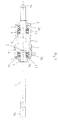
- Fig. 1 is a side view, showing the spindle unit according to the invention partly in section.
- Fig. 2 is a side view corresponding to Fig. 1 but showing a planar view of the spindle unit.
- Fig. 1 shows in side view and partly in section the components of a low fiction precision spindle unit according to the present invention.
- the unit incorporates an elongated shaft 1, having a first end 1a and a second end 1b and at least one collar 2, provided between its first and second ends.
- a tubular, substantially sleeve-formed bearing housing 3 having a first end 3a and a second end 3b is provided to enclose the shaft 1 over a portion between the first and second ends 1a, 1b of the shaft.
- a first rolling bearing 4 preferably - and here shown as - a deep groove ball bearing, is mounted with its inner race ring on the shaft in abutting contact against one side face of the collar 2.
- first bearing 4 is mounted with a tight fit in the interior of the bearing housing near the second end 3b thereof, whereby this first bearing 4 is a locating bearing, i.e. it is not displaceable relative to the bearing housing 3 or to the shaft 1, although the inner race ring thereof can be mounted with a loose fit on the shaft.
- first end 3a the bearing housing 3 is further provided with a cylindrical portion of bigger inner diameter ending at a distance from the first end 3a with a radial shoulder 5 facing the said first end 3a of the bearing housing.
- a second rolling bearing 6, also in this case preferably a deep groove ball bearing, is arranged as a free bearing on the shaft 1 with loose fit both on the shaft 1 and in the cylindrical portion of bigger diameter in the bearing housing 3.
- this second bearing 6 abuts the shoulder 5 in the bearing housing and is biased against this by means of a resilient member, such as a spring 7, the other end of which rests against a locking washer 8 being firmly arrested to the shaft 1, e.g. by interference fit. It is also important that the two bearings used are positioned as far apart in axial direction as possible, as this will give a more stiff and stable performance.
- a locking washer 9 which is firmly fitted to the shaft e.g. with an interference fit, and which has an annular, axially projecting flange 9a abutting the side face of the first rolling bearing 4 opposite to the collar 2 on the shaft 1.
- the inner race ring of the first bearing 4 is clamped between the collar 2 on the shaft and the flange 9a.
- the second bearing 6 is a free bearing which has its inner race ring biased by the spring 7 towards the first bearing these two bearings will be arranged in back-to-back arrangement, and therefore axial loads acting in both directions can be accommodated, and a stiff arrangement with ability to take up tilting moments is obtained.
- the locking washers 8 and 9 which are firmly fitted to the shaft 1 extend radially outside the inner bore of the bearing housing 3 and they are positioned so relative to the end faces of the bearing housing, that a narrow slot 10 is obtained between each end face of the bearing housing and the end face of the associated locking washer facing it.
- Each one of the first and the second bearings 4, 6 are provided with built-in seals 11 at their sides facing outwards, and the small slot 10 between each locking washer and the bearing housing provides a further labyrinth seal, which latter also has an ability during rapid mutual rotation of the shaft and the bearing housing to give a pumping effect out of the bearing housing rather than a suction effect into the bearing housing. Thereby the interior of the bearing housing is very well sealed off from the environment.
- the outer envelope surface of the bearing housing in the embodiment shown is provided with a cental recessed portion 12, and it furthermore has a circumferential groove 13 in which is positioned a resilient, compressible member 14, preferably an O-ring member.
- the spindle unit is primarily intended for supporting a spool of a fishing reel, whereby the recessed portion 12 in the outside of the bearing housing provides shoulders for taking up axial loads in one direction and also defining the position of the spindle unit and its internal bearings in relation to the spool, and the resilient O-ring member 14 provides for radial freedom of play between the bearing housing 3 and the surrounding member, i.e. in the embodiment illustrated a fishing reel spool.
- Fig. 2 shows a view corresponding to Fig. 1 but without incorporating any sectional portions, and from this view is seen the outer appearance of the spindle unit in the embodiment intended for a fishing reel spool.
- the shaft 1 is preferably a stainless steel shaft, whereas the bearing housing 3 is made from aluminium.
- the external surface of the bearing housing is provided with an anodic coating.
- the locking washers 8, 9 are preferably made from brass, whereas the O-ring member preferably is a standard O-ring of rubber.
Landscapes
- Life Sciences & Earth Sciences (AREA)
- Environmental Sciences (AREA)
- Engineering & Computer Science (AREA)
- General Engineering & Computer Science (AREA)
- Animal Husbandry (AREA)
- Biodiversity & Conservation Biology (AREA)
- Mechanical Engineering (AREA)
- Support Of The Bearing (AREA)
- Rolling Contact Bearings (AREA)
- Sealing Of Bearings (AREA)
Abstract
a shoulder (5) projecting inwards inwardly in the housing, against which shoulder the side of the inwardly directed outer race ring of the second rolling bearing (6) is engaging,
whereby the second bearing (6) by influence from the resilient member (7) is biased between the resilient member (7) and the first inwardly facing shoulder (5) in the housing, the locking washers (8,9) to define a slot seal (10) at each axial side of the housing, whereby each one of the first and the second rolling bearings (4, 6), at their outwardly facing sides are provided with an integral seal (11).
Description
- The present invention refers to a precision spindle unit for low friction performance and intended to be incorporated in rotary systems, requiring high stability and aiming at very low losses and making possible high rotational speeds.
- Such spindle units can for instance be used in hobby articles, toys, measuring instruments and e.g. for fishing reels for supporting the spool thereof in a manner giving a reliable and smooth operation and also being advantageous from noise aspects, etcetera.
- One factor for determining the quality of a fishing reel is the so called free spool rotation time, which is defined as the time such a spool will continue to rotate after it has been subjected to a defined influence. The calculation of the free spool rotation time is accomplished thus that the reel is attached to a fixture with the spool arranged substantially horizontal. A line of 500 mm length attached to a 20 g lead weight is affixed to the spool via a tape. Then the line is wound up on the spool, and the weight then is dropped. The time is measured from the moment the weight is dropped until the spool as stopped rotating.
- One purpose of the present invention is to provide a spindle unit having so good operation properties that it will give the spool of a fishing reel, supported thereby, a time of free spool rotation, which is substantially increased, and this is achieved by means of an improved spindle unit which has been given the features defined in the accompanying
claim 1. - However as earlier said the spindle unit according to the invention is not limited to such an application but can be used also in other applications where a smooth low friction performance is required.
- Hereinafter the invention will be further described with reference to a non-limiting embodiment illustrated in the accompanying drawing.
- Fig. 1 is a side view, showing the spindle unit according to the invention partly in section.
- Fig. 2 is a side view corresponding to Fig. 1 but showing a planar view of the spindle unit.
- Fig. 1 shows in side view and partly in section the components of a low fiction precision spindle unit according to the present invention. The unit incorporates an
elongated shaft 1, having a first end 1a and a second end 1b and at least onecollar 2, provided between its first and second ends. A tubular, substantially sleeve-formed bearinghousing 3 having a first end 3a and asecond end 3b is provided to enclose theshaft 1 over a portion between the first and second ends 1a, 1b of the shaft. A first rolling bearing 4, preferably - and here shown as - a deep groove ball bearing, is mounted with its inner race ring on the shaft in abutting contact against one side face of thecollar 2. The outer race ring of this first bearing 4 is mounted with a tight fit in the interior of the bearing housing near thesecond end 3b thereof, whereby this first bearing 4 is a locating bearing, i.e. it is not displaceable relative to the bearinghousing 3 or to theshaft 1, although the inner race ring thereof can be mounted with a loose fit on the shaft. At its opposite, first end 3a the bearinghousing 3 is further provided with a cylindrical portion of bigger inner diameter ending at a distance from the first end 3a with aradial shoulder 5 facing the said first end 3a of the bearing housing. A second rolling bearing 6, also in this case preferably a deep groove ball bearing, is arranged as a free bearing on theshaft 1 with loose fit both on theshaft 1 and in the cylindrical portion of bigger diameter in thebearing housing 3. The outer race ring of this second bearing 6 abuts theshoulder 5 in the bearing housing and is biased against this by means of a resilient member, such as a spring 7, the other end of which rests against alocking washer 8 being firmly arrested to theshaft 1, e.g. by interference fit. It is also important that the two bearings used are positioned as far apart in axial direction as possible, as this will give a more stiff and stable performance. - At the
second side 3b of the bearing housing is also provided alocking washer 9, which is firmly fitted to the shaft e.g. with an interference fit, and which has an annular, axially projectingflange 9a abutting the side face of the first rolling bearing 4 opposite to thecollar 2 on theshaft 1. Thus the inner race ring of the first bearing 4 is clamped between thecollar 2 on the shaft and theflange 9a. As the second bearing 6 is a free bearing which has its inner race ring biased by the spring 7 towards the first bearing these two bearings will be arranged in back-to-back arrangement, and therefore axial loads acting in both directions can be accommodated, and a stiff arrangement with ability to take up tilting moments is obtained. - The
locking washers shaft 1 extend radially outside the inner bore of the bearinghousing 3 and they are positioned so relative to the end faces of the bearing housing, that anarrow slot 10 is obtained between each end face of the bearing housing and the end face of the associated locking washer facing it. Each one of the first and the second bearings 4, 6 are provided with built-inseals 11 at their sides facing outwards, and thesmall slot 10 between each locking washer and the bearing housing provides a further labyrinth seal, which latter also has an ability during rapid mutual rotation of the shaft and the bearing housing to give a pumping effect out of the bearing housing rather than a suction effect into the bearing housing. Thereby the interior of the bearing housing is very well sealed off from the environment. - The low friction performance achieved with the precision spindle as described permits very high rotational speeds, as a result of the low losses.
- The outer envelope surface of the bearing housing in the embodiment shown is provided with a cental recessed
portion 12, and it furthermore has acircumferential groove 13 in which is positioned a resilient,compressible member 14, preferably an O-ring member. - The actual design of the outer envelope surface of the bearing housing of course is to be adapted to the purpose for which the spindle unit is intended. In the embodiment illustrated and described the spindle unit is primarily intended for supporting a spool of a fishing reel, whereby the
recessed portion 12 in the outside of the bearing housing provides shoulders for taking up axial loads in one direction and also defining the position of the spindle unit and its internal bearings in relation to the spool, and the resilient O-ring member 14 provides for radial freedom of play between the bearinghousing 3 and the surrounding member, i.e. in the embodiment illustrated a fishing reel spool.
Fig. 2 shows a view corresponding to Fig. 1 but without incorporating any sectional portions, and from this view is seen the outer appearance of the spindle unit in the embodiment intended for a fishing reel spool. - In the embodiment described and illustrated the
shaft 1 is preferably a stainless steel shaft, whereas the bearinghousing 3 is made from aluminium. Preferably the external surface of the bearing housing is provided with an anodic coating. Thelocking washers - Although the invention has been shown and described in connection with a specific bearing arrangement intended for a specific, it is evident that the bearing arrangement and the intended use as mentioned above can be changed without departing from the scope of the appended claims.
Claims (5)
- A precision spindle unit for low friction performance, incorporating in combination:an elongated shaft (1),a tubular housing (3) surrounding the shaft and having a bigger inner diameter than the diameter of the shaft,in the interior of the housing a first rolling bearing (4) mounted on the shaft and abutting with a first side of its inner race ring against a shoulder (2) provided on the shaft,a first locking washer (9) affixed to the shaft with an interference fit and provided with an axial annular flange (9a), which engages the second side of the inner race ring of the first rolling bearing (4), thus that this first bearing is axially arrested between the shoulder (2) on the shaft and the annular flange (9a) on the first locking washer (9),a second rolling bearing (6) provided in the interior of the housing (3) and having a loose fit on the shaft,a second locking washer (8) fitted with interference fit to the shaft,a resilient member (7) provided between the second locking washer (8) and the side of the inner race ring of the second rolling bearing (6), which is facing axially outwards,a first annular shoulder (5) projecting inwards from the inner surface of the housing, against which shoulder the side of the inwardly directed outer race ring of the second rolling bearing (6) is engaging,whereby the second bearing (6) by influence from the resilient member (7) is biased between the resilient member (7) and the first inwardly facing shoulder (5) in the housing,the first and the second locking washers (8,9) being arranged to extend radially along at least a portion of the tubular material of the housing at a short distance from the opposed side faces (3a, 3b) of the housing thereby forming with this a slot seal (10) at each axial side of the housing, whereby each one of the first and the second rolling bearings (4, 6), at their outwardly facing sides are provided with an integral seal (11).
- A precision spindle unit as claimed in claim 1,
characterized therein,
that the first and second bearings (4, 6) are positioned as far from each other as permitted by axial length of the bearing housing (3). - A precision spindle unit as claimed in claim 1 or 2,
characterized therein,
that the first and second rolling bearings (4, 6) are both deep groove ball bearings, whereby one of the ball bearings (4) is a locating bearing and the other is a free bearing (6), the biasing of the free bearing (6) towards the locating bearing (4) by means of said resilient member (7), thereby causing the bearing combination to be positioned in a back-to-back arrangement. - A precision spindle unit as claimed in anyone of claims 1 to 3,
characterized therein,
that the resilient member (7) is a spring of stainless steel arranged around the shaft (1). - A precision spindle unit as claimed in anyone of the preceding claims,
characterized therein,
that the sleeve-formed bearing housing (3) is made of aluminium and has an anodic coating on the external surface.
Applications Claiming Priority (2)
| Application Number | Priority Date | Filing Date | Title |
|---|---|---|---|
| SE0100317 | 2001-02-01 | ||
| SE0100317A SE518489C2 (en) | 2001-02-01 | 2001-02-01 | Precision spindle assembly for low friction function |
Publications (2)
| Publication Number | Publication Date |
|---|---|
| EP1228687A1 true EP1228687A1 (en) | 2002-08-07 |
| EP1228687B1 EP1228687B1 (en) | 2005-04-13 |
Family
ID=20282816
Family Applications (1)
| Application Number | Title | Priority Date | Filing Date |
|---|---|---|---|
| EP02445011A Expired - Lifetime EP1228687B1 (en) | 2001-02-01 | 2002-01-30 | Precision spindle unit for low friction performance |
Country Status (6)
| Country | Link |
|---|---|
| US (1) | US6623166B2 (en) |
| EP (1) | EP1228687B1 (en) |
| JP (1) | JP3630663B2 (en) |
| CN (1) | CN1166871C (en) |
| DE (1) | DE60203651T2 (en) |
| SE (1) | SE518489C2 (en) |
Cited By (1)
| Publication number | Priority date | Publication date | Assignee | Title |
|---|---|---|---|---|
| EP1557578A1 (en) * | 2004-01-20 | 2005-07-27 | Aktiebolaget SKF | Weatherproof low friction spindle unit |
Families Citing this family (24)
| Publication number | Priority date | Publication date | Assignee | Title |
|---|---|---|---|---|
| US7677041B2 (en) * | 2006-10-11 | 2010-03-16 | Woollenweber William E | Bearing systems for high-speed rotating machinery |
| US8439637B2 (en) * | 2009-11-20 | 2013-05-14 | United Technologies Corporation | Bellows preload and centering spring for a fan drive gear system |
| CA2730109A1 (en) * | 2010-04-28 | 2011-10-28 | Mitsubishi Heavy Industries, Ltd. | Direct-drive wind turbine generator and bearing structure |
| CN102312926A (en) * | 2011-03-11 | 2012-01-11 | 许晓华 | Straight-axis bearing positioning structure |
| US8777793B2 (en) | 2011-04-27 | 2014-07-15 | United Technologies Corporation | Fan drive planetary gear system integrated carrier and torque frame |
| US9038366B2 (en) | 2012-01-31 | 2015-05-26 | United Technologies Corporation | LPC flowpath shape with gas turbine engine shaft bearing configuration |
| US10400629B2 (en) | 2012-01-31 | 2019-09-03 | United Technologies Corporation | Gas turbine engine shaft bearing configuration |
| US8863491B2 (en) | 2012-01-31 | 2014-10-21 | United Technologies Corporation | Gas turbine engine shaft bearing configuration |
| US8523448B1 (en) * | 2012-08-22 | 2013-09-03 | The Timken Company | X-ray tube bearing |
| CN103148100B (en) * | 2013-03-12 | 2015-04-22 | 北京空间飞行器总体设计部 | Sliding pair acting by force of rolling friction |
| JP5913254B2 (en) * | 2013-10-30 | 2016-04-27 | グローブライド株式会社 | Fishing reel |
| DE102014212208A1 (en) * | 2014-06-25 | 2015-12-31 | Robert Bosch Gmbh | Swash plate machine |
| JP6582377B2 (en) * | 2014-09-08 | 2019-10-02 | 日本精工株式会社 | Dental air turbine |
| CN104597578A (en) * | 2014-12-17 | 2015-05-06 | 中国科学院上海光学精密机械研究所 | Centering universal regulating mechanism for optical element |
| CN104500587B (en) * | 2014-12-18 | 2017-08-29 | 重庆赛力盟电机有限责任公司 | The hydraulic turbine or motor bearings axial pretightening device |
| DE102016008824B4 (en) | 2016-07-19 | 2020-12-10 | Gebrüder Reinfurt GmbH & Co. KG | Roller bearing arrangement and X-ray tube bearing |
| IT201700101128A1 (en) * | 2017-09-11 | 2019-03-11 | Skf Ab | ASSEMBLY OF BEARING AND GASKET IN COMBINATION WITH COMMON EXTERNAL BODY |
| CN107963430A (en) * | 2017-12-11 | 2018-04-27 | 浙江湖州中盟智能科技有限公司 | A kind of Multifucntional good fortune is taken turns |
| CN107975539A (en) * | 2017-12-27 | 2018-05-01 | 安徽库伯密封技术有限公司 | A kind of hub bearing seal washer and its sealing structure |
| JP7227807B2 (en) * | 2019-03-18 | 2023-02-22 | シマノコンポネンツ マレーシア エスディーエヌ.ビーエッチディー. | fishing reel |
| CN112378655B (en) * | 2020-10-27 | 2025-08-15 | 湖北宣合科技有限公司 | An axial locking mechanism |
| WO2022169927A1 (en) * | 2021-02-04 | 2022-08-11 | Pure Fishing, Inc. | Handle knob with no free play |
| JP7666976B2 (en) * | 2021-04-22 | 2025-04-22 | 株式会社シマノ | Fishing reels |
| CN115191642A (en) * | 2022-07-15 | 2022-10-18 | 红云红河烟草(集团)有限责任公司 | Cigarette machine rubber roll positioner and cigarette machine |
Citations (1)
| Publication number | Priority date | Publication date | Assignee | Title |
|---|---|---|---|---|
| US4131245A (en) * | 1977-01-31 | 1978-12-26 | Shimano Industrial Company Limited | Fishing reel having an improved drag mechanism |
Family Cites Families (6)
| Publication number | Priority date | Publication date | Assignee | Title |
|---|---|---|---|---|
| US2531610A (en) * | 1948-05-27 | 1950-11-28 | Sr Lester E Butzman | Clutch and brake mechanism for fishing reels |
| US2836473A (en) * | 1957-07-26 | 1958-05-27 | Clarence W Tydeman | Mounting for preloading tapered roller bearings |
| GB1316433A (en) * | 1969-06-30 | 1973-05-09 | Timken Co | Rolling bearings |
| SE357799B (en) * | 1971-10-14 | 1973-07-09 | Atlas Copco Ab | |
| US4363527A (en) * | 1980-12-29 | 1982-12-14 | Howard Thrasher | Split race bearing |
| US5564840A (en) * | 1996-01-02 | 1996-10-15 | The Torrington Company | Preload adjustment apparatus and method |
-
2001
- 2001-02-01 SE SE0100317A patent/SE518489C2/en not_active IP Right Cessation
-
2002
- 2002-01-24 JP JP2002015213A patent/JP3630663B2/en not_active Expired - Fee Related
- 2002-01-30 DE DE60203651T patent/DE60203651T2/en not_active Expired - Lifetime
- 2002-01-30 CN CNB021032335A patent/CN1166871C/en not_active Expired - Fee Related
- 2002-01-30 EP EP02445011A patent/EP1228687B1/en not_active Expired - Lifetime
- 2002-02-01 US US10/060,367 patent/US6623166B2/en not_active Expired - Fee Related
Patent Citations (1)
| Publication number | Priority date | Publication date | Assignee | Title |
|---|---|---|---|---|
| US4131245A (en) * | 1977-01-31 | 1978-12-26 | Shimano Industrial Company Limited | Fishing reel having an improved drag mechanism |
Cited By (3)
| Publication number | Priority date | Publication date | Assignee | Title |
|---|---|---|---|---|
| EP1557578A1 (en) * | 2004-01-20 | 2005-07-27 | Aktiebolaget SKF | Weatherproof low friction spindle unit |
| US7125172B2 (en) | 2004-01-20 | 2006-10-24 | Aktiebolaget Skf | Weatherproof low friction spindle unit |
| CN100376816C (en) * | 2004-01-20 | 2008-03-26 | Skf公司 | All-weather low-friction spindle unit |
Also Published As
| Publication number | Publication date |
|---|---|
| DE60203651D1 (en) | 2005-05-19 |
| DE60203651T2 (en) | 2006-03-02 |
| SE0100317D0 (en) | 2001-02-01 |
| JP2002327736A (en) | 2002-11-15 |
| CN1369653A (en) | 2002-09-18 |
| SE518489C2 (en) | 2002-10-15 |
| US6623166B2 (en) | 2003-09-23 |
| SE0100317L (en) | 2002-08-02 |
| US20020114551A1 (en) | 2002-08-22 |
| EP1228687B1 (en) | 2005-04-13 |
| JP3630663B2 (en) | 2005-03-16 |
| CN1166871C (en) | 2004-09-15 |
Similar Documents
| Publication | Publication Date | Title |
|---|---|---|
| EP1228687B1 (en) | Precision spindle unit for low friction performance | |
| US4854750A (en) | Zero clearance bearing system | |
| KR900013221A (en) | Antifriction bearing assembly | |
| JP2004040926A5 (en) | ||
| JP2012500944A (en) | Extension member for bearing flinger | |
| JP6385347B2 (en) | mechanical seal | |
| US5711617A (en) | Dustcap for bearing assembly | |
| KR101748176B1 (en) | Sealed rotational output unit and sealed motor assembly | |
| JP2017025822A5 (en) | ||
| KR20120027188A (en) | Washer and motor bearing system using same | |
| CN100564933C (en) | Rotating shaft device | |
| US9765791B2 (en) | Turbo compressor | |
| CN105264244A (en) | Spherical plain bearing with spring-ball configuration | |
| US3563619A (en) | Bearings | |
| US3759592A (en) | Memory disc drive spindle | |
| US4167845A (en) | Axial guide for the shaft of a spinning rotor | |
| EP1557578B1 (en) | Weatherproof low friction spindle unit | |
| US20120037245A1 (en) | Swivel connector for a fluid handling system | |
| US2403460A (en) | Ball bearing | |
| RU101133U1 (en) | LABYRINTH SEALING OF A ROLLING BEARING | |
| WO2018097979A3 (en) | Radial rolling bearing with means for alignment | |
| CN216411678U (en) | Optical fiber disc locking device of ring winding machine | |
| CN219098253U (en) | Deviation correcting mechanism and unreeling device | |
| JP2025176320A (en) | Cylindrical bearings for fishing reels | |
| JP2528846Y2 (en) | Spindle motor |
Legal Events
| Date | Code | Title | Description |
|---|---|---|---|
| PUAI | Public reference made under article 153(3) epc to a published international application that has entered the european phase |
Free format text: ORIGINAL CODE: 0009012 |
|
| AK | Designated contracting states |
Kind code of ref document: A1 Designated state(s): AT BE CH CY DE DK ES FI FR GB GR IE IT LI LU MC NL PT SE TR |
|
| AX | Request for extension of the european patent |
Free format text: AL;LT;LV;MK;RO;SI |
|
| 17P | Request for examination filed |
Effective date: 20030207 |
|
| AKX | Designation fees paid |
Designated state(s): DE FR GB IT |
|
| GRAP | Despatch of communication of intention to grant a patent |
Free format text: ORIGINAL CODE: EPIDOSNIGR1 |
|
| GRAS | Grant fee paid |
Free format text: ORIGINAL CODE: EPIDOSNIGR3 |
|
| GRAA | (expected) grant |
Free format text: ORIGINAL CODE: 0009210 |
|
| AK | Designated contracting states |
Kind code of ref document: B1 Designated state(s): DE FR GB IT |
|
| REG | Reference to a national code |
Ref country code: GB Ref legal event code: FG4D |
|
| REG | Reference to a national code |
Ref country code: IE Ref legal event code: FG4D |
|
| REF | Corresponds to: |
Ref document number: 60203651 Country of ref document: DE Date of ref document: 20050519 Kind code of ref document: P |
|
| ET | Fr: translation filed | ||
| PLBE | No opposition filed within time limit |
Free format text: ORIGINAL CODE: 0009261 |
|
| STAA | Information on the status of an ep patent application or granted ep patent |
Free format text: STATUS: NO OPPOSITION FILED WITHIN TIME LIMIT |
|
| 26N | No opposition filed |
Effective date: 20060116 |
|
| PGFP | Annual fee paid to national office [announced via postgrant information from national office to epo] |
Ref country code: FR Payment date: 20100205 Year of fee payment: 9 Ref country code: IT Payment date: 20100126 Year of fee payment: 9 |
|
| PGFP | Annual fee paid to national office [announced via postgrant information from national office to epo] |
Ref country code: DE Payment date: 20100127 Year of fee payment: 9 Ref country code: GB Payment date: 20100125 Year of fee payment: 9 |
|
| GBPC | Gb: european patent ceased through non-payment of renewal fee |
Effective date: 20110130 |
|
| REG | Reference to a national code |
Ref country code: FR Ref legal event code: ST Effective date: 20110930 |
|
| PG25 | Lapsed in a contracting state [announced via postgrant information from national office to epo] |
Ref country code: FR Free format text: LAPSE BECAUSE OF NON-PAYMENT OF DUE FEES Effective date: 20110131 |
|
| PG25 | Lapsed in a contracting state [announced via postgrant information from national office to epo] |
Ref country code: GB Free format text: LAPSE BECAUSE OF NON-PAYMENT OF DUE FEES Effective date: 20110130 |
|
| REG | Reference to a national code |
Ref country code: DE Ref legal event code: R119 Ref document number: 60203651 Country of ref document: DE Effective date: 20110802 |
|
| PG25 | Lapsed in a contracting state [announced via postgrant information from national office to epo] |
Ref country code: IT Free format text: LAPSE BECAUSE OF NON-PAYMENT OF DUE FEES Effective date: 20110130 |
|
| PG25 | Lapsed in a contracting state [announced via postgrant information from national office to epo] |
Ref country code: DE Free format text: LAPSE BECAUSE OF NON-PAYMENT OF DUE FEES Effective date: 20110802 |