EP1227982B1 - Seal jaw modules for reclose bag modification to vertical form, fill, and seal packaging system - Google Patents
Seal jaw modules for reclose bag modification to vertical form, fill, and seal packaging system Download PDFInfo
- Publication number
- EP1227982B1 EP1227982B1 EP00959346A EP00959346A EP1227982B1 EP 1227982 B1 EP1227982 B1 EP 1227982B1 EP 00959346 A EP00959346 A EP 00959346A EP 00959346 A EP00959346 A EP 00959346A EP 1227982 B1 EP1227982 B1 EP 1227982B1
- Authority
- EP
- European Patent Office
- Prior art keywords
- facings
- seal
- module
- reclose
- sealing
- Prior art date
- Legal status (The legal status is an assumption and is not a legal conclusion. Google has not performed a legal analysis and makes no representation as to the accuracy of the status listed.)
- Expired - Lifetime
Links
- 230000004048 modification Effects 0.000 title abstract description 11
- 238000012986 modification Methods 0.000 title abstract description 11
- 238000004806 packaging method and process Methods 0.000 title description 20
- 238000007789 sealing Methods 0.000 claims abstract description 65
- 230000000712 assembly Effects 0.000 claims description 37
- 238000000429 assembly Methods 0.000 claims description 37
- 238000009434 installation Methods 0.000 claims description 24
- 239000000523 sample Substances 0.000 claims description 18
- 239000012785 packaging film Substances 0.000 claims description 10
- 229920006280 packaging film Polymers 0.000 claims description 10
- 230000015572 biosynthetic process Effects 0.000 claims description 9
- 239000013598 vector Substances 0.000 claims description 7
- 238000000034 method Methods 0.000 claims description 6
- 238000005520 cutting process Methods 0.000 claims description 5
- 238000004519 manufacturing process Methods 0.000 claims description 4
- 238000013459 approach Methods 0.000 claims description 2
- 238000013461 design Methods 0.000 abstract description 14
- 208000027418 Wounds and injury Diseases 0.000 abstract description 2
- 230000006378 damage Effects 0.000 abstract description 2
- 208000014674 injury Diseases 0.000 abstract description 2
- 238000002955 isolation Methods 0.000 abstract 1
- 235000013305 food Nutrition 0.000 description 6
- 230000006870 function Effects 0.000 description 5
- 230000004888 barrier function Effects 0.000 description 4
- 230000008859 change Effects 0.000 description 4
- 230000008901 benefit Effects 0.000 description 3
- 238000012423 maintenance Methods 0.000 description 3
- 229910000760 Hardened steel Inorganic materials 0.000 description 2
- 238000010438 heat treatment Methods 0.000 description 2
- 239000000463 material Substances 0.000 description 2
- 235000008371 tortilla/corn chips Nutrition 0.000 description 2
- 239000004606 Fillers/Extenders Substances 0.000 description 1
- 239000004743 Polypropylene Substances 0.000 description 1
- 230000009471 action Effects 0.000 description 1
- 230000004913 activation Effects 0.000 description 1
- 230000006978 adaptation Effects 0.000 description 1
- 230000002411 adverse Effects 0.000 description 1
- 238000009826 distribution Methods 0.000 description 1
- 230000000694 effects Effects 0.000 description 1
- 230000006872 improvement Effects 0.000 description 1
- 238000011900 installation process Methods 0.000 description 1
- 239000002184 metal Substances 0.000 description 1
- 239000004033 plastic Substances 0.000 description 1
- -1 polypropylene Polymers 0.000 description 1
- 229920001155 polypropylene Polymers 0.000 description 1
- 235000013606 potato chips Nutrition 0.000 description 1
- 238000003825 pressing Methods 0.000 description 1
- 230000008569 process Effects 0.000 description 1
- 230000008439 repair process Effects 0.000 description 1
- 235000011888 snacks Nutrition 0.000 description 1
- 238000003860 storage Methods 0.000 description 1
- 238000012546 transfer Methods 0.000 description 1
Images




Classifications
-
- B—PERFORMING OPERATIONS; TRANSPORTING
- B29—WORKING OF PLASTICS; WORKING OF SUBSTANCES IN A PLASTIC STATE IN GENERAL
- B29C—SHAPING OR JOINING OF PLASTICS; SHAPING OF MATERIAL IN A PLASTIC STATE, NOT OTHERWISE PROVIDED FOR; AFTER-TREATMENT OF THE SHAPED PRODUCTS, e.g. REPAIRING
- B29C66/00—General aspects of processes or apparatus for joining preformed parts
- B29C66/80—General aspects of machine operations or constructions and parts thereof
- B29C66/84—Specific machine types or machines suitable for specific applications
- B29C66/841—Machines or tools adaptable for making articles of different dimensions or shapes or for making joints of different dimensions
- B29C66/8412—Machines or tools adaptable for making articles of different dimensions or shapes or for making joints of different dimensions of different length, width or height
- B29C66/84121—Machines or tools adaptable for making articles of different dimensions or shapes or for making joints of different dimensions of different length, width or height of different width
-
- B—PERFORMING OPERATIONS; TRANSPORTING
- B29—WORKING OF PLASTICS; WORKING OF SUBSTANCES IN A PLASTIC STATE IN GENERAL
- B29C—SHAPING OR JOINING OF PLASTICS; SHAPING OF MATERIAL IN A PLASTIC STATE, NOT OTHERWISE PROVIDED FOR; AFTER-TREATMENT OF THE SHAPED PRODUCTS, e.g. REPAIRING
- B29C65/00—Joining or sealing of preformed parts, e.g. welding of plastics materials; Apparatus therefor
- B29C65/02—Joining or sealing of preformed parts, e.g. welding of plastics materials; Apparatus therefor by heating, with or without pressure
- B29C65/18—Joining or sealing of preformed parts, e.g. welding of plastics materials; Apparatus therefor by heating, with or without pressure using heated tools
-
- B—PERFORMING OPERATIONS; TRANSPORTING
- B29—WORKING OF PLASTICS; WORKING OF SUBSTANCES IN A PLASTIC STATE IN GENERAL
- B29C—SHAPING OR JOINING OF PLASTICS; SHAPING OF MATERIAL IN A PLASTIC STATE, NOT OTHERWISE PROVIDED FOR; AFTER-TREATMENT OF THE SHAPED PRODUCTS, e.g. REPAIRING
- B29C65/00—Joining or sealing of preformed parts, e.g. welding of plastics materials; Apparatus therefor
- B29C65/02—Joining or sealing of preformed parts, e.g. welding of plastics materials; Apparatus therefor by heating, with or without pressure
- B29C65/18—Joining or sealing of preformed parts, e.g. welding of plastics materials; Apparatus therefor by heating, with or without pressure using heated tools
- B29C65/24—Joining or sealing of preformed parts, e.g. welding of plastics materials; Apparatus therefor by heating, with or without pressure using heated tools characterised by the means for heating the tool
- B29C65/30—Electrical means
- B29C65/305—Electrical means involving the use of cartridge heaters
-
- B—PERFORMING OPERATIONS; TRANSPORTING
- B29—WORKING OF PLASTICS; WORKING OF SUBSTANCES IN A PLASTIC STATE IN GENERAL
- B29C—SHAPING OR JOINING OF PLASTICS; SHAPING OF MATERIAL IN A PLASTIC STATE, NOT OTHERWISE PROVIDED FOR; AFTER-TREATMENT OF THE SHAPED PRODUCTS, e.g. REPAIRING
- B29C65/00—Joining or sealing of preformed parts, e.g. welding of plastics materials; Apparatus therefor
- B29C65/74—Joining or sealing of preformed parts, e.g. welding of plastics materials; Apparatus therefor by welding and severing, or by joining and severing, the severing being performed in the area to be joined, next to the area to be joined, in the joint area or next to the joint area
- B29C65/745—Joining or sealing of preformed parts, e.g. welding of plastics materials; Apparatus therefor by welding and severing, or by joining and severing, the severing being performed in the area to be joined, next to the area to be joined, in the joint area or next to the joint area using a single unit having both a severing tool and a welding tool
- B29C65/7451—Joining or sealing of preformed parts, e.g. welding of plastics materials; Apparatus therefor by welding and severing, or by joining and severing, the severing being performed in the area to be joined, next to the area to be joined, in the joint area or next to the joint area using a single unit having both a severing tool and a welding tool the severing tool and the welding tool being movable with respect to one-another
-
- B—PERFORMING OPERATIONS; TRANSPORTING
- B29—WORKING OF PLASTICS; WORKING OF SUBSTANCES IN A PLASTIC STATE IN GENERAL
- B29C—SHAPING OR JOINING OF PLASTICS; SHAPING OF MATERIAL IN A PLASTIC STATE, NOT OTHERWISE PROVIDED FOR; AFTER-TREATMENT OF THE SHAPED PRODUCTS, e.g. REPAIRING
- B29C66/00—General aspects of processes or apparatus for joining preformed parts
- B29C66/01—General aspects dealing with the joint area or with the area to be joined
- B29C66/05—Particular design of joint configurations
- B29C66/10—Particular design of joint configurations particular design of the joint cross-sections
- B29C66/11—Joint cross-sections comprising a single joint-segment, i.e. one of the parts to be joined comprising a single joint-segment in the joint cross-section
- B29C66/112—Single lapped joints
- B29C66/1122—Single lap to lap joints, i.e. overlap joints
-
- B—PERFORMING OPERATIONS; TRANSPORTING
- B29—WORKING OF PLASTICS; WORKING OF SUBSTANCES IN A PLASTIC STATE IN GENERAL
- B29C—SHAPING OR JOINING OF PLASTICS; SHAPING OF MATERIAL IN A PLASTIC STATE, NOT OTHERWISE PROVIDED FOR; AFTER-TREATMENT OF THE SHAPED PRODUCTS, e.g. REPAIRING
- B29C66/00—General aspects of processes or apparatus for joining preformed parts
- B29C66/40—General aspects of joining substantially flat articles, e.g. plates, sheets or web-like materials; Making flat seams in tubular or hollow articles; Joining single elements to substantially flat surfaces
- B29C66/41—Joining substantially flat articles ; Making flat seams in tubular or hollow articles
- B29C66/43—Joining a relatively small portion of the surface of said articles
- B29C66/431—Joining the articles to themselves
- B29C66/4312—Joining the articles to themselves for making flat seams in tubular or hollow articles, e.g. transversal seams
-
- B—PERFORMING OPERATIONS; TRANSPORTING
- B29—WORKING OF PLASTICS; WORKING OF SUBSTANCES IN A PLASTIC STATE IN GENERAL
- B29C—SHAPING OR JOINING OF PLASTICS; SHAPING OF MATERIAL IN A PLASTIC STATE, NOT OTHERWISE PROVIDED FOR; AFTER-TREATMENT OF THE SHAPED PRODUCTS, e.g. REPAIRING
- B29C66/00—General aspects of processes or apparatus for joining preformed parts
- B29C66/40—General aspects of joining substantially flat articles, e.g. plates, sheets or web-like materials; Making flat seams in tubular or hollow articles; Joining single elements to substantially flat surfaces
- B29C66/47—Joining single elements to sheets, plates or other substantially flat surfaces
- B29C66/472—Joining single elements to sheets, plates or other substantially flat surfaces said single elements being substantially flat
-
- B—PERFORMING OPERATIONS; TRANSPORTING
- B29—WORKING OF PLASTICS; WORKING OF SUBSTANCES IN A PLASTIC STATE IN GENERAL
- B29C—SHAPING OR JOINING OF PLASTICS; SHAPING OF MATERIAL IN A PLASTIC STATE, NOT OTHERWISE PROVIDED FOR; AFTER-TREATMENT OF THE SHAPED PRODUCTS, e.g. REPAIRING
- B29C66/00—General aspects of processes or apparatus for joining preformed parts
- B29C66/40—General aspects of joining substantially flat articles, e.g. plates, sheets or web-like materials; Making flat seams in tubular or hollow articles; Joining single elements to substantially flat surfaces
- B29C66/47—Joining single elements to sheets, plates or other substantially flat surfaces
- B29C66/474—Joining single elements to sheets, plates or other substantially flat surfaces said single elements being substantially non-flat
-
- B—PERFORMING OPERATIONS; TRANSPORTING
- B29—WORKING OF PLASTICS; WORKING OF SUBSTANCES IN A PLASTIC STATE IN GENERAL
- B29C—SHAPING OR JOINING OF PLASTICS; SHAPING OF MATERIAL IN A PLASTIC STATE, NOT OTHERWISE PROVIDED FOR; AFTER-TREATMENT OF THE SHAPED PRODUCTS, e.g. REPAIRING
- B29C66/00—General aspects of processes or apparatus for joining preformed parts
- B29C66/70—General aspects of processes or apparatus for joining preformed parts characterised by the composition, physical properties or the structure of the material of the parts to be joined; Joining with non-plastics material
- B29C66/73—General aspects of processes or apparatus for joining preformed parts characterised by the composition, physical properties or the structure of the material of the parts to be joined; Joining with non-plastics material characterised by the intensive physical properties of the material of the parts to be joined, by the optical properties of the material of the parts to be joined, by the extensive physical properties of the parts to be joined, by the state of the material of the parts to be joined or by the material of the parts to be joined being a thermoplastic or a thermoset
- B29C66/737—General aspects of processes or apparatus for joining preformed parts characterised by the composition, physical properties or the structure of the material of the parts to be joined; Joining with non-plastics material characterised by the intensive physical properties of the material of the parts to be joined, by the optical properties of the material of the parts to be joined, by the extensive physical properties of the parts to be joined, by the state of the material of the parts to be joined or by the material of the parts to be joined being a thermoplastic or a thermoset characterised by the state of the material of the parts to be joined
- B29C66/7373—Joining soiled or oxidised materials
-
- B—PERFORMING OPERATIONS; TRANSPORTING
- B29—WORKING OF PLASTICS; WORKING OF SUBSTANCES IN A PLASTIC STATE IN GENERAL
- B29C—SHAPING OR JOINING OF PLASTICS; SHAPING OF MATERIAL IN A PLASTIC STATE, NOT OTHERWISE PROVIDED FOR; AFTER-TREATMENT OF THE SHAPED PRODUCTS, e.g. REPAIRING
- B29C66/00—General aspects of processes or apparatus for joining preformed parts
- B29C66/80—General aspects of machine operations or constructions and parts thereof
- B29C66/81—General aspects of the pressing elements, i.e. the elements applying pressure on the parts to be joined in the area to be joined, e.g. the welding jaws or clamps
- B29C66/814—General aspects of the pressing elements, i.e. the elements applying pressure on the parts to be joined in the area to be joined, e.g. the welding jaws or clamps characterised by the design of the pressing elements, e.g. of the welding jaws or clamps
- B29C66/8141—General aspects of the pressing elements, i.e. the elements applying pressure on the parts to be joined in the area to be joined, e.g. the welding jaws or clamps characterised by the design of the pressing elements, e.g. of the welding jaws or clamps characterised by the surface geometry of the part of the pressing elements, e.g. welding jaws or clamps, coming into contact with the parts to be joined
- B29C66/81431—General aspects of the pressing elements, i.e. the elements applying pressure on the parts to be joined in the area to be joined, e.g. the welding jaws or clamps characterised by the design of the pressing elements, e.g. of the welding jaws or clamps characterised by the surface geometry of the part of the pressing elements, e.g. welding jaws or clamps, coming into contact with the parts to be joined comprising a single cavity, e.g. a groove
-
- B—PERFORMING OPERATIONS; TRANSPORTING
- B29—WORKING OF PLASTICS; WORKING OF SUBSTANCES IN A PLASTIC STATE IN GENERAL
- B29C—SHAPING OR JOINING OF PLASTICS; SHAPING OF MATERIAL IN A PLASTIC STATE, NOT OTHERWISE PROVIDED FOR; AFTER-TREATMENT OF THE SHAPED PRODUCTS, e.g. REPAIRING
- B29C66/00—General aspects of processes or apparatus for joining preformed parts
- B29C66/80—General aspects of machine operations or constructions and parts thereof
- B29C66/81—General aspects of the pressing elements, i.e. the elements applying pressure on the parts to be joined in the area to be joined, e.g. the welding jaws or clamps
- B29C66/814—General aspects of the pressing elements, i.e. the elements applying pressure on the parts to be joined in the area to be joined, e.g. the welding jaws or clamps characterised by the design of the pressing elements, e.g. of the welding jaws or clamps
- B29C66/8141—General aspects of the pressing elements, i.e. the elements applying pressure on the parts to be joined in the area to be joined, e.g. the welding jaws or clamps characterised by the design of the pressing elements, e.g. of the welding jaws or clamps characterised by the surface geometry of the part of the pressing elements, e.g. welding jaws or clamps, coming into contact with the parts to be joined
- B29C66/81433—General aspects of the pressing elements, i.e. the elements applying pressure on the parts to be joined in the area to be joined, e.g. the welding jaws or clamps characterised by the design of the pressing elements, e.g. of the welding jaws or clamps characterised by the surface geometry of the part of the pressing elements, e.g. welding jaws or clamps, coming into contact with the parts to be joined being toothed, i.e. comprising several teeth or pins, or being patterned
- B29C66/81435—General aspects of the pressing elements, i.e. the elements applying pressure on the parts to be joined in the area to be joined, e.g. the welding jaws or clamps characterised by the design of the pressing elements, e.g. of the welding jaws or clamps characterised by the surface geometry of the part of the pressing elements, e.g. welding jaws or clamps, coming into contact with the parts to be joined being toothed, i.e. comprising several teeth or pins, or being patterned comprising several parallel ridges, e.g. for crimping
-
- B—PERFORMING OPERATIONS; TRANSPORTING
- B29—WORKING OF PLASTICS; WORKING OF SUBSTANCES IN A PLASTIC STATE IN GENERAL
- B29C—SHAPING OR JOINING OF PLASTICS; SHAPING OF MATERIAL IN A PLASTIC STATE, NOT OTHERWISE PROVIDED FOR; AFTER-TREATMENT OF THE SHAPED PRODUCTS, e.g. REPAIRING
- B29C66/00—General aspects of processes or apparatus for joining preformed parts
- B29C66/80—General aspects of machine operations or constructions and parts thereof
- B29C66/81—General aspects of the pressing elements, i.e. the elements applying pressure on the parts to be joined in the area to be joined, e.g. the welding jaws or clamps
- B29C66/816—General aspects of the pressing elements, i.e. the elements applying pressure on the parts to be joined in the area to be joined, e.g. the welding jaws or clamps characterised by the mounting of the pressing elements, e.g. of the welding jaws or clamps
- B29C66/8167—Quick change joining tools or surfaces
-
- B—PERFORMING OPERATIONS; TRANSPORTING
- B29—WORKING OF PLASTICS; WORKING OF SUBSTANCES IN A PLASTIC STATE IN GENERAL
- B29C—SHAPING OR JOINING OF PLASTICS; SHAPING OF MATERIAL IN A PLASTIC STATE, NOT OTHERWISE PROVIDED FOR; AFTER-TREATMENT OF THE SHAPED PRODUCTS, e.g. REPAIRING
- B29C66/00—General aspects of processes or apparatus for joining preformed parts
- B29C66/80—General aspects of machine operations or constructions and parts thereof
- B29C66/82—Pressure application arrangements, e.g. transmission or actuating mechanisms for joining tools or clamps
- B29C66/822—Transmission mechanisms
- B29C66/8221—Scissor or lever mechanisms, i.e. involving a pivot point
-
- B—PERFORMING OPERATIONS; TRANSPORTING
- B29—WORKING OF PLASTICS; WORKING OF SUBSTANCES IN A PLASTIC STATE IN GENERAL
- B29C—SHAPING OR JOINING OF PLASTICS; SHAPING OF MATERIAL IN A PLASTIC STATE, NOT OTHERWISE PROVIDED FOR; AFTER-TREATMENT OF THE SHAPED PRODUCTS, e.g. REPAIRING
- B29C66/00—General aspects of processes or apparatus for joining preformed parts
- B29C66/80—General aspects of machine operations or constructions and parts thereof
- B29C66/83—General aspects of machine operations or constructions and parts thereof characterised by the movement of the joining or pressing tools
- B29C66/832—Reciprocating joining or pressing tools
- B29C66/8322—Joining or pressing tools reciprocating along one axis
- B29C66/83221—Joining or pressing tools reciprocating along one axis cooperating reciprocating tools, each tool reciprocating along one axis
-
- B—PERFORMING OPERATIONS; TRANSPORTING
- B29—WORKING OF PLASTICS; WORKING OF SUBSTANCES IN A PLASTIC STATE IN GENERAL
- B29C—SHAPING OR JOINING OF PLASTICS; SHAPING OF MATERIAL IN A PLASTIC STATE, NOT OTHERWISE PROVIDED FOR; AFTER-TREATMENT OF THE SHAPED PRODUCTS, e.g. REPAIRING
- B29C66/00—General aspects of processes or apparatus for joining preformed parts
- B29C66/80—General aspects of machine operations or constructions and parts thereof
- B29C66/84—Specific machine types or machines suitable for specific applications
- B29C66/849—Packaging machines
- B29C66/8491—Packaging machines welding through a filled container, e.g. tube or bag
-
- B—PERFORMING OPERATIONS; TRANSPORTING
- B29—WORKING OF PLASTICS; WORKING OF SUBSTANCES IN A PLASTIC STATE IN GENERAL
- B29C—SHAPING OR JOINING OF PLASTICS; SHAPING OF MATERIAL IN A PLASTIC STATE, NOT OTHERWISE PROVIDED FOR; AFTER-TREATMENT OF THE SHAPED PRODUCTS, e.g. REPAIRING
- B29C66/00—General aspects of processes or apparatus for joining preformed parts
- B29C66/90—Measuring or controlling the joining process
- B29C66/91—Measuring or controlling the joining process by measuring or controlling the temperature, the heat or the thermal flux
- B29C66/912—Measuring or controlling the joining process by measuring or controlling the temperature, the heat or the thermal flux by measuring the temperature, the heat or the thermal flux
- B29C66/9121—Measuring or controlling the joining process by measuring or controlling the temperature, the heat or the thermal flux by measuring the temperature, the heat or the thermal flux by measuring the temperature
- B29C66/91211—Measuring or controlling the joining process by measuring or controlling the temperature, the heat or the thermal flux by measuring the temperature, the heat or the thermal flux by measuring the temperature with special temperature measurement means or methods
- B29C66/91212—Measuring or controlling the joining process by measuring or controlling the temperature, the heat or the thermal flux by measuring the temperature, the heat or the thermal flux by measuring the temperature with special temperature measurement means or methods involving measurement means being part of the welding jaws, e.g. integrated in the welding jaws
-
- B—PERFORMING OPERATIONS; TRANSPORTING
- B29—WORKING OF PLASTICS; WORKING OF SUBSTANCES IN A PLASTIC STATE IN GENERAL
- B29C—SHAPING OR JOINING OF PLASTICS; SHAPING OF MATERIAL IN A PLASTIC STATE, NOT OTHERWISE PROVIDED FOR; AFTER-TREATMENT OF THE SHAPED PRODUCTS, e.g. REPAIRING
- B29C66/00—General aspects of processes or apparatus for joining preformed parts
- B29C66/90—Measuring or controlling the joining process
- B29C66/91—Measuring or controlling the joining process by measuring or controlling the temperature, the heat or the thermal flux
- B29C66/912—Measuring or controlling the joining process by measuring or controlling the temperature, the heat or the thermal flux by measuring the temperature, the heat or the thermal flux
- B29C66/9121—Measuring or controlling the joining process by measuring or controlling the temperature, the heat or the thermal flux by measuring the temperature, the heat or the thermal flux by measuring the temperature
- B29C66/91231—Measuring or controlling the joining process by measuring or controlling the temperature, the heat or the thermal flux by measuring the temperature, the heat or the thermal flux by measuring the temperature of the joining tool
-
- B—PERFORMING OPERATIONS; TRANSPORTING
- B65—CONVEYING; PACKING; STORING; HANDLING THIN OR FILAMENTARY MATERIAL
- B65B—MACHINES, APPARATUS OR DEVICES FOR, OR METHODS OF, PACKAGING ARTICLES OR MATERIALS; UNPACKING
- B65B51/00—Devices for, or methods of, sealing or securing package folds or closures; Devices for gathering or twisting wrappers, or necks of bags
- B65B51/10—Applying or generating heat or pressure or combinations thereof
- B65B51/26—Devices specially adapted for producing transverse or longitudinal seams in webs or tubes
- B65B51/30—Devices, e.g. jaws, for applying pressure and heat, e.g. for subdividing filled tubes
- B65B51/303—Devices, e.g. jaws, for applying pressure and heat, e.g. for subdividing filled tubes reciprocating along only one axis
-
- B—PERFORMING OPERATIONS; TRANSPORTING
- B65—CONVEYING; PACKING; STORING; HANDLING THIN OR FILAMENTARY MATERIAL
- B65B—MACHINES, APPARATUS OR DEVICES FOR, OR METHODS OF, PACKAGING ARTICLES OR MATERIALS; UNPACKING
- B65B61/00—Auxiliary devices, not otherwise provided for, for operating on sheets, blanks, webs, binding material, containers or packages
- B65B61/18—Auxiliary devices, not otherwise provided for, for operating on sheets, blanks, webs, binding material, containers or packages for making package-opening or unpacking elements
- B65B61/188—Auxiliary devices, not otherwise provided for, for operating on sheets, blanks, webs, binding material, containers or packages for making package-opening or unpacking elements by applying or incorporating profile-strips, e.g. for reclosable bags
-
- B—PERFORMING OPERATIONS; TRANSPORTING
- B29—WORKING OF PLASTICS; WORKING OF SUBSTANCES IN A PLASTIC STATE IN GENERAL
- B29C—SHAPING OR JOINING OF PLASTICS; SHAPING OF MATERIAL IN A PLASTIC STATE, NOT OTHERWISE PROVIDED FOR; AFTER-TREATMENT OF THE SHAPED PRODUCTS, e.g. REPAIRING
- B29C66/00—General aspects of processes or apparatus for joining preformed parts
- B29C66/90—Measuring or controlling the joining process
- B29C66/91—Measuring or controlling the joining process by measuring or controlling the temperature, the heat or the thermal flux
- B29C66/912—Measuring or controlling the joining process by measuring or controlling the temperature, the heat or the thermal flux by measuring the temperature, the heat or the thermal flux
- B29C66/9131—Measuring or controlling the joining process by measuring or controlling the temperature, the heat or the thermal flux by measuring the temperature, the heat or the thermal flux by measuring the heat or the thermal flux, i.e. the heat flux
- B29C66/91311—Measuring or controlling the joining process by measuring or controlling the temperature, the heat or the thermal flux by measuring the temperature, the heat or the thermal flux by measuring the heat or the thermal flux, i.e. the heat flux by measuring the heat generated by Joule heating or induction heating
- B29C66/91317—Measuring or controlling the joining process by measuring or controlling the temperature, the heat or the thermal flux by measuring the temperature, the heat or the thermal flux by measuring the heat or the thermal flux, i.e. the heat flux by measuring the heat generated by Joule heating or induction heating by measuring the electrical resistance
-
- B—PERFORMING OPERATIONS; TRANSPORTING
- B29—WORKING OF PLASTICS; WORKING OF SUBSTANCES IN A PLASTIC STATE IN GENERAL
- B29L—INDEXING SCHEME ASSOCIATED WITH SUBCLASS B29C, RELATING TO PARTICULAR ARTICLES
- B29L2005/00—Elements of slide fasteners
-
- B—PERFORMING OPERATIONS; TRANSPORTING
- B29—WORKING OF PLASTICS; WORKING OF SUBSTANCES IN A PLASTIC STATE IN GENERAL
- B29L—INDEXING SCHEME ASSOCIATED WITH SUBCLASS B29C, RELATING TO PARTICULAR ARTICLES
- B29L2031/00—Other particular articles
- B29L2031/712—Containers; Packaging elements or accessories, Packages
- B29L2031/7128—Bags, sacks, sachets
-
- B—PERFORMING OPERATIONS; TRANSPORTING
- B31—MAKING ARTICLES OF PAPER, CARDBOARD OR MATERIAL WORKED IN A MANNER ANALOGOUS TO PAPER; WORKING PAPER, CARDBOARD OR MATERIAL WORKED IN A MANNER ANALOGOUS TO PAPER
- B31B—MAKING CONTAINERS OF PAPER, CARDBOARD OR MATERIAL WORKED IN A MANNER ANALOGOUS TO PAPER
- B31B70/00—Making flexible containers, e.g. envelopes or bags
- B31B70/74—Auxiliary operations
- B31B70/81—Forming or attaching accessories, e.g. opening devices, closures or tear strings
- B31B70/813—Applying closures
- B31B70/8131—Making bags having interengaging closure elements
- B31B70/8133—Applying the closure elements in the cross direction
Definitions
- the present invention relates to a reclose or zipper seal jaw design for use in a sealing carriage of a vertical form and fill packaging machine, and, in particular, to a quick-change, reclosable zipper seal jaw module and standard or "return” module that can accommodate variable bag sizes.
- the modules are self-aligning, easily installed on existing bridge assembly hardware, and incorporate several safety enhancements.
- Vertical form, fill, and seal packaging machines are commonly used in the snack food industry for forming, filling, and sealing bags of chips and other like products.
- Such packaging machines take a packaging film, such as polypropylene, from a sheet roll of said film, and forms the film into a vertical tube around a product delivery cylinder.
- the vertical tube is vertically sealed along its length to form a back seal.
- the machine applies a pair of heat-sealing jaws or facings against the tube to form a transverse seal.
- This transverse seal acts as the top seal on the bag below and the bottom seal on the package being filled and formed above.
- the film tube is pushed downward to draw out another package length.
- the package below the transverse seal is separated by cutting across the sealed area.
- the product to be packaged is dropped through the product delivery cylinder and formed tube and is held within the tube above the bottom transverse seal.
- the sealing jaws Prior to forming the upper transverse seal, the sealing jaws are brought together in two steps. First, a pair of stripping plates or bars are brought into contact with the film in order to flatten the tube and strip product out of the area to be sealed. Second, the final closing movement of the jaws is performed, thereby forming the transverse seal.
- FIG. 1a shows a sealing carriage on a prior art form, fill, and seal packaging machine.
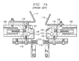
- Figure 1b is a cross-section of a prior art facing assembly installed in said carriage.
- Opposed transverse seal jaw facings 102 , 104 (hereinafter referred to by Applicants as "jaw facings") are shown attached to opposed bridge assemblies 106 , 108.
- Behind each jaw facing 102,104 is a heat probe 128, 130 capable of heating the exposed surface of the jaw facings up to 405°F during operation.
- a heat separator 136, 138 Placed between the jaw facings 102, 104 and their respective bridge assemblies 106, 108.
- the heat separators 136 , 138 provide a thermal barrier between the jaw facings 102 , 104 and the bridge assembly 106, 108 in order to minimize heat transfer to the bridge assembly 106, 108 and other components attached thereto.
- a thermocouple or thermoster 132, 134 is placed between the heat separator 136, 138 and the heat probe 128, 130 in order to monitor the jaw facing 102, 104 temperature.
- a transverse seal is formed when a tube of film placed between the jaw facings 102,104 is flattened as the jaw facings 102, 104 are brought in close proximity to each other. This is accomplished by both bridge assemblies 106, 108 traversing towards each other while riding on two stationary rods 110, 112.
- a pair of opposed crumb plates 114,116 are also shown attached to the bridge assemblies 106, 108.
- the stripper bars 118 , 120 are typically spring loaded and provide the stripping function previously described.
- Both of the jaw facings 102, 104 are constructed with a central channel 141, 143 to accommodate a knife or cutting tool 122.
- This knife 122 is recessed within the channel 141 of one of the jaw facings 102 and held in place by two knife brackets 124, 126 attached to the bridge assemblies 106, 108.
- the knife brackets 124, 126 are rotated slightly, thereby exposing the knife 122 to the transverse seal. This action cuts the transverse seal, thereby completing the process of forming, filling, and sealing a single package.
- the prior art carriage described above is designed such that the jaw facings 102, 104 can be removed in order to install jaw facings 102, 104 that provide for different vertical widths of the resultant transverse seals.
- the facing assembly shown in Figure 1b is aligned at the factory, and removal from the sealing carriage by the operator of more than the jaw facings 102, 104, crumb plates 114, 116, and stripper bars 118, 120 is not recommended.
- Such design is also not easily adapted to the formation of a zipper seal along with the standard transverse seal.
- a form, fill, and seal packaging system must be substantially modified when it is used to install a zipper seal at the top of the package.
- a zipper seal is a resealable barrier that can be installed on the top end of a bag either immediately below or above the upper transverse seal. After the consumer breaks the upper transverse seal to gain access to the product within the package, the zipper seal can be reclosed, thereby keeping the product fresh.
- Such package is referred to as a "reclose” bag. Consequently, the terms “zipper seal module” and “reclose module,” and many other descriptive terms using as adjectives the words “zipper” or “reclose,” are used herein by Applicants interchangeably.
- Figures 2a and 2b show one embodiment of a reclose food package 281 incorporating a zipper seal 283.
- Figure 2a is a perspective view of a flexible, plastic package or bag 281 used to contain potato chips, tortilla chips, and the like.
- Figure 2b is a cross-section of the top of said bag 281.
- the food package 281 shown is typical in that it has an upper transverse seal 285 and a lower transverse seal 287.
- this bag also uniquely incorporates a zipper or reclose seal 283 immediately below the upper transverse seal 285.
- the zipper seal 283 is made up of a male engagement member 291 and a female engagement member 289.
- the package 281 is opened for the first time by pulling on the exterior walls of the package 281 below the zipper seal 283.
- the two opposed members 289, 291 separate, thereby opening the zipper seal 283. Stress can then be exerted on the upper transverse seal 285 until it opens. Once this occurs, the package 281 is fully opened and the product, such as tortilla chips 293, may be consumed.
- the package 281 can then be resealed by applying pressure to the exterior of the package 281 along the zipper seal 283, thereby forcing the male engagement member 291 back into the female engagement member 289.
- This novel reclose bag design is described in detail in United States Patent Application number 09/079,382 filed on May 15, 1998.
- the opposed members 289, 291 (of the zipper seal 283) must be heat sealed to the inside surface of the food package 281. Further, these opposed members 289, 291 must be heat-sealed together at each end 295, 297. This is accomplished by applying a heat and pressure sealing device to an outer areas of the zipper seal 283.
- the film that enters a form and fill machine to form the reclose package 281 shown in Figure 2a is typically a continuous sheet with graphics presented on one side.
- the side of the sheet on which the graphics are presented will ultimately comprise the outside of the package 281.
- the unprinted side of the sheet will ultimately comprise the inside of the package 281.
- zipper seals 283 Prior to entering the form and fill machine, zipper seals 283 must be attached to the inside film surface by securing one of the opposed members 289, 291 on the inside surface of the film with the zipper seal 283 in the closed configuration position.
- the zipper seal 283 thus secured should be oriented such that when the upper transverse seal 285 is formed on the package 281, the zipper seal 283 is located in its proper position below and parallel to the upper transverse seal 285.
- Figures 3a and 3b illustrate one prior art embodiment known to Applicants of a modification of a sealing carriage to accommodate the formation of a reclose bag.
- Figure 3a is a perspective view of a modified sealing carriage
- Figure 3b is a cross-section of the modified facing assembly.
- a second set of opposed facings 340, 342 have been installed below the first opposed set of facings 302, 304.
- the second set of opposed facings 340, 342 are the means for sealing the zipper below the transverse seal on the reclose bag.
- zipper seal jaw facings 340, 342 and referred to herein by Applicants as “zipper seal facings.”
- the stripper bars 318, 320 are now attached below the zipper seal facings 340, 342.
- Each of the zipper seal facings 340, 342 must also have a respective heat probe 344, 346 and thermosters 348, 350.
- the facings 102,104 can accommodate any required bag width up to the total width of the facings 102,104.
- the bag length is easily adjusted by changing the amount of film travel below the facings 102, 104.
- converting a prior art vertical form, fill, and seal machine from the configuration shown in Figures 1a and 1b to the configuration shown in Figures 3a and 3b requires extensive modifications to the machine to allow for additional attaching points, electrical connections, controls, and to accommodate additional stripper travel. Once these modifications are made, it typically takes several hours to install the additional set of facings and accompanying heat probes, stripper plates, and other required items. It then takes an additional several hours to reconvert the assembly back to a standard transverse seal configuration.
- prior art reclose designs allow for the production of only one bag width for any given set of zipper seal facings 340, 342. This is due to the fact that the zipper seal facings 340, 342 have a rectangular shaped recess in order to accommodate the zipper seal while at the same time sealing the zipper seal at each end and around its edges to the inside of the bag. If a change in bag size is required for a reclose bag, the zipper seal facings 340, 342 must be removed from the reclose assembly and replaced with a new zipper seal facing 340, 342 to accommodate the new bag's width. This again takes two to four hours to accomplish, thereby requiring additional man hours and reducing the efficiency of the packaging facility.
- the zipper seal facings 340, 342 are also expensive items, presently costing approximately $7,500.00 per each set of facings 340 , 342 .
- Capital investment must therefore be made for every conceivable bag width so that a specific sized zipper seal facing 340, 342 can be on hand whenever a corresponding bag width needs to be run on the form and fill machine in the reclose configuration.
- Effective stripping widths for a transverse seal 285 are on the order of 0,76 mm (.030 inches), while effective stripping widths for a zipper seal 283 are on the order of .125 inches. Consequently, stripping efficiency of the transverse seal area is lost because the strippers must be set to accommodate the thicker zipper seal 283 located below. Further, the chassis or frame of the form and fill machine must be modified to allow space for stripping in light of the addition of components below the existing facings and accompanying stripper bars. The alternative is to limit the amount of stripping travel, which in turn limits the ability to remove product from the sealing areas.
- Figure 3b shows two force vectors F indicating that the force exerted on the assembly is centered along the axis of travel of bridge assemblies 306, 308 along the stationary rods 310, 312. These force vectors typically produce a pressure of 68,9827 bar (1000 to 1200 psi) along the facings 302 , 304 during seal formation.
- the rigidity of the facing assembly shown in Figure 3b is not sufficient to equally distribute this pressure because of the cantilevered location of the zipper seal facings 340, 342 away from the centerline of the supporting bridge assemblies 306, 308.
- the zipper seal facings 340, 342 act as lever arms rotating away from the force F centered on the bridge assemblies 306, 308. Unless this phenomena is counteracted, sufficient pressure cannot be applied on the zipper seal to adequately and uniformly attach it to the inside of the bag.
- a prior art fix to this problem is to install springs (not shown) behind the zipper seal facings 340, 342 in order to counteract the rotating effect. This fix has been demonstrated to reduce the overall pressure applied by the carriage assembly on the bag film. To counteract this loss of pressure, the heat or the dwell time must be increased, or both. Increasing the dwell time reduces the productivity of the bag maker, while heat can only be increased to a certain level before other adverse consequences are experienced.
- This zipper seal jaw module should incorporate safety features to keep the operator away from heat sources and should physically lock in the closed position in order to avoid inadvertent closure of the device on the operator's hands during removal or installation.
- the module should be self-aligning and quickly installable with a minimal number of tools.
- the module design should allow for a uniform application of pressure during the sealing mode between the jaw facings and the zipper seal facings. Further, the orientation of the module should allow for no interference with the form and fill machine chassis during stripping and promote increased stripping efficiency.
- a single module should be easily convertible to handle any width reclose bag without the need to stock and replace various sizes of zipper facings.
- the invention should also incorporate a standard return module that can be quickly and easily substituted for the reclose module to return the form and fill package machine to standard transverse seal operation.
- a reclose module for installation on the bridge assemblies of a sealing carriage, said module comprising: two support members; two opposed zipper seal facings, each attached to a respective support member; two opposed jaw facings, each attached to a respective support member; and wherein, upon installation of the support members on said bridge assemblies, the zipper seal facings and jaw facings are located approximately equidistant from the axis of the force vectors transmitted from the bridge assemblies to the support members during sealing operations and the jaw facings are below the zipper seal facings, further wherein said reclose module is a single unit that can be installed on and removed from the sealing carriage as a unit.
- the reclose module further comprises: aligning handles attachable to said support members when the module is in a closed position, and wherein such aligning handle retains the comprising elements of the reclose module in relative position and as a single unit in the event the reclose module is removed from the bridge assemblies.
- At least one of the zipper seal facings comprises a slotted channel for receiving end inserts.
- the reclose module further comprises: two crumb plates, each attached to a respective support member.
- the reclose module further comprises: two stripper bars, each attached to a respective support member.
- the reclose module further comprises: a heat probe in contact with at least one jaw facing; a heat probe in contact with at least one zipper seal facing; wires connected to each of said heat probes; and at least one electrical quick-connect for connecting said heat probes to controls on a form and fill machine.
- the reclose module further comprises: a knife adapter attached to one bridge assembly for orienting a knife to a jaw facing.
- a method for manufacturing a reclose bag with a vertical form, fill, and seal machine comprising the steps of:
- the pressure applied by the form and fill machine during the sealing steps (c) and (f) is generally uniform about the contact surface of the film tube.
- the preferred embodiment of the invention comprises a quick-change zipper seal jaw module and accompanying return module that are self-aligning and easily installed in less than fifteen minutes with a single standard tool.
- the zipper seal module uses two rigid support members to support an opposed pair of zipper seal facings and an opposed pair of jaw facings.
- the support members can also support crumb plates and stripper bars, as needed.
- Each support member is easily attached to an existing bridge assembly with one or more bolts.
- Each support member also has at least one threaded receiver for receiving a bolt from an aligning tool. This aligning tool holds the opposed facings together in an aligned position when the module is being installed, removed, or while in storage.
- the heating requirements of the module are completely self-contained and connected to electrical quick-connect plugs which mate with quick-connect outlets installed on the chassis of the form and fill machine.
- the zipper facings are located above the jaw facings in one embodiment of the invention. This requires that the package film be run upside-down, but also increases stripping efficiency, since the thicker zipper seal is located further from the product level in the bag during sealing. Further, the zipper seal facings and jaw facings are oriented such that the pressure applied on the module by the bridge assemblies during a sealing step is generally distributed equally about all facing contact surfaces. A knife adapter is provided to move the location of the knife to the repositioned jaw facings.
- the zipper seal facing is constructed of a slotted channel that allows for the installation of end inserts. This allows for the same zipper facing to be used to make varying widths of reclose bags by merely changing the size of the end inserts or moving the inserts relative to each other within the slotted channel.
- the preferred embodiment of the invention also provides for a "return" module which returns the vertical form, fill, and seal machine to a standard transverse seal configuration using the same mounting hardware as used with the reclose or zipper seal module.
- the return module is also self-aligning by use of an alignment handle.
- the preferred embodiment of the invention is a great improvement over the prior art for a number of reasons.
- the time involved in changing a form and fill machine from a standard transverse seal configuration to a reclose configuration has been reduced from several hours to less than 15 minutes.
- a similar time saving is involved when adjusting the zipper seal facing of the invention for varying bag widths since the zipper seal facing need not be removed. This feature also saves a considerable amount of capital investment, since changing a reclose bag width does not require the use of a different, and expensive, size jaw facing.
- an aligning handle with both the reclose module and return module greatly increases safety during change-over operations and when required maintenance must be performed. Since the module is completely self-contained, maintenance on heat probes, thermosters, and other module components can be done off-line and away from the potential crushing hazards associated with working on sealing carriage components while the sealing carriage is in the open position. Changing facings can also be done off-line.
- the modular installation and removal using the aligning handle is done with the sealing carriage in the closed position, thereby keeping an operator away from hot components immediately after operation and reducing the chance of the facings inadvertently closing on an operator's hand.
- the preferred embodiment of the invention performs the sealing function more efficiently than prior art designs and increases stripping efficiency due to the reversed and centered relative orientation of the jaw facings and zipper seal facings. Normal dwell times and temperatures can be used while still producing uniform and acceptable transverse seals and zipper seals.
- the orientation of the facings centered on the bridge assembly also adds minimally to the vertical space required below the bridge assemblies to accommodate stripping travel. Therefore, the modules do not interfere with an existing form and fill machine chassis during the stripping phase of package formation.
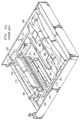
- Figures 4a and 4b illustrate one preferred embodiment of the reclose module of the present invention.
- Figure 4a is a perspective view of the reclose module installed in a prior art sealing carriage
- Figure 4b is a cross-section of the reclose module in position on the bridge assemblies 406, 408 without the aligning handle installed, which handle will be described in further detail below.
- the reclose module is self-contained comprising many of the individual components which together make up the prior art modification embodiment shown in Figures 3a and 3b.
- included within the reclose module are a pair of opposed jaw facings 402, 404, a pair of opposed zipper seal facings 440, 442, heat probes 428, 430, 444, 446, thermosters 448, 450, heat barriers 436, 438, crumb plates 414, 416, and stripper bars 418,420.
- the module itself is mounted onto the sealing carriage at the bridge assemblies 406 , 408 by four installation bolts 456, 460, two of which are shown in the cross-sectional view of Figure 4b.
- Two nut wells 464, 466 visible on Figure 4a provide access to these bolts 460 and show the relative position of the bolts 460 along the length of a bridge assembly 408.
- Figure 5 shows the two installation bolts 560, 562 that would be received by the nut wells 464, 466 shown on Figure 4a ).
- the relative vertical positioning of the facings pairs 402, 404, 440, 442 (the jaw facings 402, 404 and the zipper seal facings 440, 442 are both referred to by Applicants generically as "facings") have been reversed in the preferred embodiment illustrated.
- the zipper seal facings 440, 442 are now located above the jaw facings 402, 404. This embodiment is preferred because it reduces the need to strip through the thicker zipper seal area on the bag.
- the facings 402, 404, 440, 442 By reversing the facings 402, 404, 440, 442 relative to their vertical orientation, the zipper seal and the transverse seals can be made first before the bag is filled from what will become the bottom of the bag.
- the area most likely requiring stripping is the transverse seal area, since it is located closest to the product level in a filled bag. Consequently, the stripping gap can be set narrowly in order to efficiently strip this area.
- the only other adjustment required is that the packaging film must be run upside-down through the form and fill machine.
- Another distinct advantage of the present invention over the prior art is the added rigidity of the module and the centering of the pressure transmitted to the facings 402, 404, 440, 442 by the force vectors F acting on the bridge assemblies 406, 408.
- All of the various components that make up the reclose module are mounted on or supported by two support members 472, 474.
- Each support member 472, 474 is extremely rigid and made from a contiguous piece of metal or other suitable material such as hardened steel.
- the front support member 474 (referenced, like all other components referred to by Applicants as “front” or “rear,” from its position on the sealing carriage while viewed by an operator) is constructed to provide a snug fit about the front bridge assembly 408.
- the rear support member 472 must have some tolerance in its fit with the rear bridge assembly 406 in order to accommodate the auto-aligning feature of the invention which will be described below.
- the zipper seal facings 440, 442 and jaw facings 402, 404 have also been re-oriented so that they are more centrally aligned with the force vectors F acting on the bridge assemblies 406, 408.
- This alignment with the force vectors F combined with the rigidity provided by the design of the support members 472, 474 resolves the pressure loss problem of prior art designs whereby the prior art zipper seal facings tend to deflect away from the package film during sealing. Consequently, the present invention provides for an even distribution of pressure about the zipper facings 440, 442, and the jaw facings 402, 404. This in turn allows the form and fill machine to operate at shorter dwell times and standard temperatures.
- Figure 5 shows one embodiment of the aligning handle 576 installed on a reclose module.
- Figure 6 shows the aligning handle 676 without the reclose module attached.
- the aligning handle 676 is constructed of a rigid material, such as hardened steel, and can be of a contiguous cast design, made up of several major components welded together, or made up of several major components bolted together.
- the aligning handle has two front engaging means 678, 680 and two rear engaging means 682, 684. These engaging means 678, 680, 682, 684 in the embodiment illustrated comprise bolts with knobs at one end, but could be of any suitable design to rigidly attach the handle to modules.
- each of the four engaging means 578, 580, 582, 584 secure the opposed sections of the reclose module by twisting the respective knobs, which in turn causes the bolts 578, 580, 582, 584 to seat in threaded receivers (indicated by dashed lines 486, 488 on Figure 4b ) located in the support members 572, 574.
- threaded receivers are located such that the zipper seal facings 540, 542 and jaw facings 502, 504 are aligned once the aligning handle 576 has been properly secured to the reclose module.
- the entire reclose module can then be carried in one, self-contained package by the aligning handle 576.
- the reclose module To install the reclose module, it is placed in between the bridge assemblies while the sealing carriage is in the open position. The bridge assemblies are then slowly closed such that the installation bolts 560, 562 are directed through the respective bolt and nut wells on the receiving bridge assemblies.
- the front support member 474 is now snugly fitted about the front bridge assembly 408. Although shown apart in Figure 4b, at this stage the front and rear portions of the module would be held tightly together in an aligned position by the aligning handle.
- the rear support platform 472 allows for tolerance about the rear bridge assembly 406 in order that this alignment can be maintained while the installation bolts 456, 460 are tightened with standard nuts (not shown). Once the nuts have been tightened on the installation bolts 456, 460, the alignment handle is removed and the alignment of the module is thereafter maintained by the installation bolts 456, 460.
- an electrical quick connect plug 594 This electrical quick-connect plug 594 consolidates the wiring to various electrical components in the reclose module, such as the heat probes and thermosters.
- a receiving female outlet for this quick connect plug 594 can be installed on the modified form and fill machine chassis, thereby accommodating a quick and simple positive connection between the electrical control and inputs of the form and fill machine with the electrical components contained within the reclosed module.
- Figure 5 shows only one quick-connect plug 594
- an alternative embodiment of the reclose module comprises two quick-connect plugs, each with a wire harness directed to electrical components associated with one half of the module. Such a two-plug embodiment would require two separate receiving outlets installed on the chassis of the form and fill machine. Additional electrical controls are added to the form and fill machine to separately control the electrical components associated with the zipper seal facings 540, 542, and would be consolidated in the receiving outlets.
- the knife adapters 801, 803 comprise two extenders 805, 807 and two installation pins 809, 811.
- the installation pins 809, 811 hold the knife 822 in the knife adapters 801, 803 by positioning the knife 822 in receiving slots 813 , 815 , and passing the pins 809 , 811 through a hole 817 in either end of the knife 822.
- the knife 422 is installed on the reclose module as illustrated in Figure 4a after the reclose module is installed on the bridge assemblies 406, 408, as described above.
- the sealing carriage is then opened.
- the extensions 405 , 407 are then fitted over the existing knife brackets 424, 426.
- the knife 422 is inserted into the channel on the rear jaw facing 402.
- the installation pins 409, 411 are next inserted through holes in the end of each knife bracket 424, 426 and holes at the ends of the knife 422.
- the knife 422 can be removed by reversing the above sequence when the reclose module is removed from the sealing carriage.
- the installation of the reclose module is completed once the support member installation bolts have been installed on the bridge assemblies, the knife has been properly positioned and attached with the knife adapters, and the electrical quick-connects have been inserted into the receiving outlets on the form and fill machine chassis.
- the entire installation process takes a single tool, a standard socket wrench, and takes less than fifteen minutes.
- the reclose module is removed by first opening the sealing carriage.
- the knife and knife adapters are removed and the electrical quick-connects are disconnected from the chassis.
- the ceiling carriage is then closed.
- the aligning handle is attached to the support members as previously described.
- the nuts are then removed from the support member installation bolts.
- the sealing carriage is opened and the reclose module is lifted therefrom by the aligning handle.
- Figure 7 shows the rear zipper facing 740 for one embodiment of the present invention.
- This embodiment shows another novel feature of the invention which eliminates the need for the use of a different zipper seal facing for each different bag width run in the reclose configuration. This is accomplished by using a slotted channel 796 in combination with two inserts 798, 799. The inserts 798, 799 slide into and out of the channel, being held in place by the flange configuration of the edges of the channel and/or set screws (not shown). Rather than stocking various sizes of zipper facings having different widths of rectangular relief, different sized inserts 798, 799, used to change the horizontal distance between the two inserts 798, 799, can be kept in stock.
- inserts 798, 799 can be used and simply moved horizontally along the channel 796 in order to adjust for the appropriate bag width.
- the inserts 798, 799 themselves can have teeth on their exposed contact surface (as shown), have a flat contact surface, or any other appropriate design.
- Changing the bag width for a reclose configuration using this feature of the present invention is a relatively simple task.
- the reclose module is removed from the bridge assembly, as previously described.
- the operator next removes the reclose module to a work bench or similar area.
- the aligning handle is removed to allow access to the rear zipper facing 740.
- Inserts 798, 799 are then removed and replaced with new inserts 798, 799 sized for the bag width to be run.
- the inserts 798, 799 are repositioned along the channel in order to adjust the distance separating them for the new bag width required. Removal of the entire zipper facing 740 is not required.
- the reclose module can then be realigned and reinstalled as previously described.
- FIG. 4b shows a rear zipper seal facing 440 with an insert 498 in the slotted channel, while the opposed front zipper seal 442 comprises a flat exposed surface.
- An alternative embodiment of the invention comprises slotted channels in both the rear zipper facings 440 and the front zipper facings 442.
- the present invention utilizes what is called a "return" module, which returns the form and fill machine to the standard transverse seal operation.
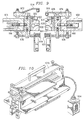
- a return module of the present invention is shown in Figure 9.
- the return module shown comprises opposed jaw facings 902 , 904 , support members 972 , 974 , heat probes 928 , 930 , thermosters 932 , 934 , crumb plates 914 , 916 , stripper bars 918, 920, and thermal barriers 936, 938.
- the support members 972, 974 are smaller than the support members used in the reclose module, but perform much the same function of maintaining a rigid support base for all of the various components that comprise the return module.
- the return module is installed on the bridge assemblies 906, 908 in a manner similar to that previously described with regard to the reclose module. Specifically, it is attached to the bridge assemblies 906, 908 by four bolts 956, 960 connected to the support members 972, 974. Since the jaw facings 902, 904 are in the same relative vertical positions as in a prior art facing assembly, a knife adapter, such as the one shown in Figure 8, is not required for the return module.
- the return module is aligned, stored, and transported using the invention's aligning handle 676, as is illustrated in Figure 6 .
- Figure 10 shows the aligning handle 1076 installed on the return module.
- the return module is also equipped with one or more electrical quick disconnect 1094 electrical connections in order to connect the various electrical components of the return module to the modified form and fill machine controls.
- the installation of the reclose module is completed after the quick disconnect 1094 is mated with a respective plug on the chassis of the form and fill machine and the aligning handle 1076 is removed.
- the return module then functions just as the prior art facing assembly described in relation to Figure 1b .
- the return module is easily installed in place of the reclose module on the modified form and fill machine of the present invention. Installation or removal of either module takes less than fifteen minutes, can be accomplished with a single standard socket wrench, and minimizes the operator's exposure to hot components and time spent with digits exposed while the sealing carriage is in the open position.
Landscapes
- Engineering & Computer Science (AREA)
- Mechanical Engineering (AREA)
- Physics & Mathematics (AREA)
- Thermal Sciences (AREA)
- Making Paper Articles (AREA)
- Containers And Plastic Fillers For Packaging (AREA)
- Bag Frames (AREA)
Abstract
Description
- The present invention relates to a reclose or zipper seal jaw design for use in a sealing carriage of a vertical form and fill packaging machine, and, in particular, to a quick-change, reclosable zipper seal jaw module and standard or "return" module that can accommodate variable bag sizes. The modules are self-aligning, easily installed on existing bridge assembly hardware, and incorporate several safety enhancements.
- Vertical form, fill, and seal packaging machines are commonly used in the snack food industry for forming, filling, and sealing bags of chips and other like products. Such packaging machines take a packaging film, such as polypropylene, from a sheet roll of said film, and forms the film into a vertical tube around a product delivery cylinder. The vertical tube is vertically sealed along its length to form a back seal. The machine applies a pair of heat-sealing jaws or facings against the tube to form a transverse seal. This transverse seal acts as the top seal on the bag below and the bottom seal on the package being filled and formed above. After the seal has been formed, the film tube is pushed downward to draw out another package length. The package below the transverse seal is separated by cutting across the sealed area.
- Before each transverse seal is formed by the sealing jaws, the product to be packaged is dropped through the product delivery cylinder and formed tube and is held within the tube above the bottom transverse seal. Prior to forming the upper transverse seal, the sealing jaws are brought together in two steps. First, a pair of stripping plates or bars are brought into contact with the film in order to flatten the tube and strip product out of the area to be sealed. Second, the final closing movement of the jaws is performed, thereby forming the transverse seal.
- The bag sealing functions of a vertical form, fill, and seal machine are best described with reference to Figures 1a and 1b. Figure 1a shows a sealing carriage on a prior art form, fill, and seal packaging machine. Figure 1b is a cross-section of a prior art facing assembly installed in said carriage. Opposed transverse
seal jaw facings 102, 104 (hereinafter referred to by Applicants as "jaw facings") are shown attached toopposed bridge assemblies heat probe jaw facings respective bridge assemblies heat separator heat separators jaw facings bridge assembly bridge assembly thermoster heat separator heat probe jaw facings bridge assemblies stationary rods - Also shown attached to the
bridge assemblies crumb plates stripper bars bridge assemblies stripper bars - Both of the
jaw facings central channel cutting tool 122. Thisknife 122 is recessed within thechannel 141 of one of thejaw facings 102 and held in place by twoknife brackets bridge assemblies knife brackets knife 122 to the transverse seal. This action cuts the transverse seal, thereby completing the process of forming, filling, and sealing a single package. - The prior art carriage described above is designed such that the
jaw facings jaw facings jaw facings crumb plates stripper bars - A zipper seal is a resealable barrier that can be installed on the top end of a bag either immediately below or above the upper transverse seal. After the consumer breaks the upper transverse seal to gain access to the product within the package, the zipper seal can be reclosed, thereby keeping the product fresh. Such package is referred to as a "reclose" bag. Consequently, the terms "zipper seal module" and "reclose module," and many other descriptive terms using as adjectives the words "zipper" or "reclose," are used herein by Applicants interchangeably.
- Figures 2a and 2b show one embodiment of a reclose
food package 281 incorporating azipper seal 283. Figure 2a is a perspective view of a flexible, plastic package orbag 281 used to contain potato chips, tortilla chips, and the like. Figure 2b is a cross-section of the top of saidbag 281. Thefood package 281 shown is typical in that it has an uppertransverse seal 285 and a lowertransverse seal 287. However, this bag also uniquely incorporates a zipper or recloseseal 283 immediately below the uppertransverse seal 285. Thezipper seal 283 is made up of amale engagement member 291 and afemale engagement member 289. - For the embodiment illustrated, the
package 281 is opened for the first time by pulling on the exterior walls of thepackage 281 below thezipper seal 283. The two opposedmembers zipper seal 283. Stress can then be exerted on the uppertransverse seal 285 until it opens. Once this occurs, thepackage 281 is fully opened and the product, such astortilla chips 293, may be consumed. Thepackage 281 can then be resealed by applying pressure to the exterior of thepackage 281 along thezipper seal 283, thereby forcing themale engagement member 291 back into thefemale engagement member 289. This novel reclose bag design is described in detail in United States Patent Application number 09/079,382 filed on May 15, 1998. - When making the
reclose bag 281 illustrated, theopposed members 289, 291 (of the zipper seal 283) must be heat sealed to the inside surface of thefood package 281. Further, these opposedmembers end zipper seal 283. - The film that enters a form and fill machine to form the
reclose package 281 shown in Figure 2a is typically a continuous sheet with graphics presented on one side. The side of the sheet on which the graphics are presented will ultimately comprise the outside of thepackage 281. The unprinted side of the sheet will ultimately comprise the inside of thepackage 281. Prior to entering the form and fill machine,zipper seals 283 must be attached to the inside film surface by securing one of theopposed members zipper seal 283 in the closed configuration position. Thezipper seal 283 thus secured should be oriented such that when the uppertransverse seal 285 is formed on thepackage 281, thezipper seal 283 is located in its proper position below and parallel to the uppertransverse seal 285. This will allow for the formation of both thetransverse seal 285 and the permanent attachment of thezipper seal 283 to the inside of thepackage 281. The simultaneous formation of thetransverse seal 285 and the installation of thezipper seal 283 can be accomplished with an extensively modified prior art sealing carriage, in part by installing a second set of facings for sealing the zipper seal into the package along with the existing set of facings. As will be described, such adaptation of an existing form and fill sealing carriage makes for a number of technical difficulties and unsatisfactory results. - Figures 3a and 3b illustrate one prior art embodiment known to Applicants of a modification of a sealing carriage to accommodate the formation of a reclose bag. Figure 3a is a perspective view of a modified sealing carriage, while Figure 3b is a cross-section of the modified facing assembly. By comparing Figures 3a and 3b with Figures 1a and 1b, it is evident that a second set of
opposed facings facings opposed facings seal jaw facings zipper seal facings zipper seal facings respective heat probe thermosters - Prior art modifications to the sealing carriage of a form and fill packaging system to accommodate the manufacture of reclose bags are not easily installed, have exhibited poor performance characteristics, raise several safety concerns, and are only suitable for one package size and zipper configuration. Consequently, the modification shown in Figures 3a and 3b is not a desirable fix. As will be explained, the purchase of a dedicated form and fill machine only capable of constructing reclose bags is also not an acceptable alternative.
- By way of background, most chip packaging facilities have on-site one to several (and perhaps as many as seven or eight) vertical form, fill, and seal packaging machines. A single packaging facility might be required in any given week to package several different product lines in numerous different bag sizes for each product line by using the same form and fill packaging machines. Each form and fill packaging machine is quite expensive, for example, in the range of $50,000 to $150,000, and represents a large capital investment. Consequently, it is critical to the economic efficiency of the packaging facility that each form and fill machine be capable of being quickly adapted to handle a variety of bag widths and lengths. This is easily done with the prior art vertical form, fill, and seal machine discussed herein for standard (non-reclose) bags. The facings 102,104 (shown in Figure 1a) can accommodate any required bag width up to the total width of the facings 102,104. The bag length is easily adjusted by changing the amount of film travel below the
facings - It is expected that a typical packaging facility will only need to dedicate a small portion of the packaging assets to the formation of reclose bags incorporating zipper seals. Consequently, a permanent changeover to a reclose bag configuration or the use of a specifically built reclose bag machine would result in such packaging machine sitting idle for long periods of time. The ability to quickly change over from a standard transverse seal configuration to a reclose configuration is, therefore, a major consideration. The present down-time involved in changing from one configuration back to the other, which is in excess of several hours, adds considerably to the labor costs in running reclose bags and reduces the overall packaging capacity of any single packaging facility.
- Along the same lines, prior art reclose designs allow for the production of only one bag width for any given set of
zipper seal facings zipper seal facings zipper seal facings zipper seal facings facings - The need to replace components on the modified carriage and facing assemblies shown in Figures 3a and 3b increases the safety hazards involved in such change over operation. In order to remove or install the
zipper facings various facings facings facings knife 122 is also extremely sharp and must be carefully removed. - The placement of the zipper seal facing 340, 342 below the standard jaw facing 302, 304 also introduces several problems. It can be seen from Figures 2b and 3b that the area that is required to be stripped of product prior to applying both a standard transverse seal and a reclose seal is approximately doubled in length compared to the area that requires stripping when only a transverse seal is formed. More importantly, with the
zipper seal 283 located below thetransverse seal 285, the zipper seal 283b is closest to the product and will always have to be stripped even if portions of thetransverse seal 285 do not require stripping. This is problematic in that thezipper seal 283 is significantly thicker than thetransverse seal 285. Effective stripping widths for atransverse seal 285 are on the order of 0,76 mm (.030 inches), while effective stripping widths for azipper seal 283 are on the order of .125 inches. Consequently, stripping efficiency of the transverse seal area is lost because the strippers must be set to accommodate thethicker zipper seal 283 located below. Further, the chassis or frame of the form and fill machine must be modified to allow space for stripping in light of the addition of components below the existing facings and accompanying stripper bars. The alternative is to limit the amount of stripping travel, which in turn limits the ability to remove product from the sealing areas. - It is also evident that the
zipper seal facings jaw facings bridge assemblies stationary rods facings zipper seal facings bridge assemblies zipper seal facings bridge assemblies zipper seal facings - Consequently, a need exists for a modular zipper seal jaw unit that can be easily removed from or installed on a prior art form and fill packaging machine sealing carriage, thereby quickly modifying the sealing carriage for a reclose configuration. This zipper seal jaw module should incorporate safety features to keep the operator away from heat sources and should physically lock in the closed position in order to avoid inadvertent closure of the device on the operator's hands during removal or installation. Ideally, the module should be self-aligning and quickly installable with a minimal number of tools. The module design should allow for a uniform application of pressure during the sealing mode between the jaw facings and the zipper seal facings. Further, the orientation of the module should allow for no interference with the form and fill machine chassis during stripping and promote increased stripping efficiency. A single module should be easily convertible to handle any width reclose bag without the need to stock and replace various sizes of zipper facings. The invention should also incorporate a standard return module that can be quickly and easily substituted for the reclose module to return the form and fill package machine to standard transverse seal operation.
- According to the present invention there is provided a reclose module for installation on the bridge assemblies of a sealing carriage, said module comprising: two support members; two opposed zipper seal facings, each attached to a respective support member; two opposed jaw facings, each attached to a respective support member; and wherein, upon installation of the support members on said bridge assemblies, the zipper seal facings and jaw facings are located approximately equidistant from the axis of the force vectors transmitted from the bridge assemblies to the support members during sealing operations and the jaw facings are below the zipper seal facings, further wherein said reclose module is a single unit that can be installed on and removed from the sealing carriage as a unit.
- Conveniently, the reclose module further comprises: aligning handles attachable to said support members when the module is in a closed position, and wherein such aligning handle retains the comprising elements of the reclose module in relative position and as a single unit in the event the reclose module is removed from the bridge assemblies.
- Preferably, at least one of the zipper seal facings comprises a slotted channel for receiving end inserts.
- Advantageously, the reclose module further comprises: two crumb plates, each attached to a respective support member.
- Conveniently, the reclose module further comprises: two stripper bars, each attached to a respective support member.
- Preferably, the reclose module further comprises: a heat probe in contact with at least one jaw facing; a heat probe in contact with at least one zipper seal facing; wires connected to each of said heat probes; and at least one electrical quick-connect for connecting said heat probes to controls on a form and fill machine.
- Advantageously, the reclose module further comprises: a knife adapter attached to one bridge assembly for orienting a knife to a jaw facing.
- In a further aspect of the present invention, there is provided a method for manufacturing a reclose bag with a vertical form, fill, and seal machine, said method comprising the steps of:
- (a) inverting the packaging film prior to the introduction of said packaging film into the form and fill machine, such that the packaging film is upside-down as it approaches a sealing carriage;.
- (b) forming said packaging film into a tube;
- (c) sealing a zipper seal to the inside of the film tube while simultaneously forming a transverse seal below said zipper seal;
- (d) moving downward the thus formed seals an approximate bag length;
- (e) introducing product into the film tube;
- (f) sealing said film tube above the product level by sealing a zipper seal to the inside of the film tube while simultaneously forming a transverse seal below said zipper seal;
- (g) cutting the transverse seal above the product level, thereby completing the formation of a single reclose bag filled with product.
- Conveniently, the pressure applied by the form and fill machine during the sealing steps (c) and (f) is generally uniform about the contact surface of the film tube.
- The preferred embodiment of the invention comprises a quick-change zipper seal jaw module and accompanying return module that are self-aligning and easily installed in less than fifteen minutes with a single standard tool. The zipper seal module uses two rigid support members to support an opposed pair of zipper seal facings and an opposed pair of jaw facings. The support members can also support crumb plates and stripper bars, as needed. Each support member is easily attached to an existing bridge assembly with one or more bolts. Each support member also has at least one threaded receiver for receiving a bolt from an aligning tool. This aligning tool holds the opposed facings together in an aligned position when the module is being installed, removed, or while in storage. The heating requirements of the module are completely self-contained and connected to electrical quick-connect plugs which mate with quick-connect outlets installed on the chassis of the form and fill machine.
- The zipper facings are located above the jaw facings in one embodiment of the invention. This requires that the package film be run upside-down, but also increases stripping efficiency, since the thicker zipper seal is located further from the product level in the bag during sealing. Further, the zipper seal facings and jaw facings are oriented such that the pressure applied on the module by the bridge assemblies during a sealing step is generally distributed equally about all facing contact surfaces. A knife adapter is provided to move the location of the knife to the repositioned jaw facings.
- In one embodiment of the invention, the zipper seal facing is constructed of a slotted channel that allows for the installation of end inserts. This allows for the same zipper facing to be used to make varying widths of reclose bags by merely changing the size of the end inserts or moving the inserts relative to each other within the slotted channel.
- The preferred embodiment of the invention also provides for a "return" module which returns the vertical form, fill, and seal machine to a standard transverse seal configuration using the same mounting hardware as used with the reclose or zipper seal module. The return module is also self-aligning by use of an alignment handle.
- The preferred embodiment of the invention is a great improvement over the prior art for a number of reasons. The time involved in changing a form and fill machine from a standard transverse seal configuration to a reclose configuration has been reduced from several hours to less than 15 minutes. A similar time saving is involved when adjusting the zipper seal facing of the invention for varying bag widths since the zipper seal facing need not be removed. This feature also saves a considerable amount of capital investment, since changing a reclose bag width does not require the use of a different, and expensive, size jaw facing.
- The use of an aligning handle with both the reclose module and return module greatly increases safety during change-over operations and when required maintenance must be performed. Since the module is completely self-contained, maintenance on heat probes, thermosters, and other module components can be done off-line and away from the potential crushing hazards associated with working on sealing carriage components while the sealing carriage is in the open position. Changing facings can also be done off-line. The modular installation and removal using the aligning handle is done with the sealing carriage in the closed position, thereby keeping an operator away from hot components immediately after operation and reducing the chance of the facings inadvertently closing on an operator's hand.
- The preferred embodiment of the invention performs the sealing function more efficiently than prior art designs and increases stripping efficiency due to the reversed and centered relative orientation of the jaw facings and zipper seal facings. Normal dwell times and temperatures can be used while still producing uniform and acceptable transverse seals and zipper seals. The orientation of the facings centered on the bridge assembly also adds minimally to the vertical space required below the bridge assemblies to accommodate stripping travel. Therefore, the modules do not interfere with an existing form and fill machine chassis during the stripping phase of package formation.
- The above as well as additional features and advantages of the present invention will become apparent in the following written detailed description.
- The novel features believed characteristic of the invention are set forth in the appended claims. The invention itself, however, as well as a preferred mode of use, further objectives and advantages thereof, will be best understood by reference to the following detailed description of illustrative embodiments when read in conjunction with the accompanying drawings, wherein:
- Figure 1a is a perspective view in elevation of a prior art sealing carriage;
- Figure 1b is a cross-section of a prior art facing assembly;
- Figure 2a is a perspective representation of a food package incorporating a zipper seal;bcross-section of the top portion of a food package incorporating a zipper seal;
- Figure2 ais a side viewperspective view in elevation of a prior art modification to a sealing carriage to accommodate a reclose configuration;
- Figure 33b is a cross-section of a prior art modification to a facing assembly to accommodate a reclose configuration;
- Figure 4a is a perspective view in elevation of the reclose module of the present invention installed on a prior art sealing carriage;
- Figure 4b is a cross-section of the reclose module of the present invention;
- Figure 5 is a perspective view in elevation of the reclose module of the present invention with an aligning handle installed;
- Figure 6 is a perspective view in elevation of the aligning handle of the present invention;
- Figure 7 is a perspective view in elevation of one embodiment of a zipper seal facing of the present invention;
- Figure 8 is a perspective view in elevation of the knife assembly of the present invention;
- Figure 9 is a cross-section view of the return module of the present invention; and
- Figure 10 is a perspective view in elevation of the return module of the present invention with handles.
- Figures 4a and 4b illustrate one preferred embodiment of the reclose module of the present invention. Figure 4a is a perspective view of the reclose module installed in a prior art sealing carriage, while Figure 4b is a cross-section of the reclose module in position on the
bridge assemblies - The reclose module is self-contained comprising many of the individual components which together make up the prior art modification embodiment shown in Figures 3a and 3b. With reference to Figure 4b, included within the reclose module are a pair of
opposed jaw facings zipper seal facings thermosters heat barriers crumb plates - The module itself is mounted onto the sealing carriage at the
bridge assemblies installation bolts nut wells bolts 460 and show the relative position of thebolts 460 along the length of abridge assembly 408. (Figure 5 shows the twoinstallation bolts nut wells bridge assemblies bolts - The relative vertical positioning of the facings pairs 402, 404, 440, 442 (the
jaw facings zipper seal facings zipper seal facings jaw facings facings - Another distinct advantage of the present invention over the prior art is the added rigidity of the module and the centering of the pressure transmitted to the
facings bridge assemblies support members support member front bridge assembly 408. Therear support member 472 must have some tolerance in its fit with therear bridge assembly 406 in order to accommodate the auto-aligning feature of the invention which will be described below. Second, thezipper seal facings jaw facings bridge assemblies support members zipper facings jaw facings - As noted previously, prior art reclose facing assembly designs do not allow for removal of components from the bridge assemblies, as the alignment of the facing is factory set. Consequently, most repair work that must be done on the prior art facing assembly, such as the replacement of heat probes or thermosters, must take place with the prior art facing assembly installed on the bridge assemblies. This exposes the operator to many of the safety hazards previously discussed. The present invention, however, provides for a self-aligning feature that is accomplished prior to installing the module on the
bridge assemblies - Figure 5 shows one embodiment of the aligning
handle 576 installed on a reclose module. Figure 6 shows the aligninghandle 676 without the reclose module attached. The aligninghandle 676 is constructed of a rigid material, such as hardened steel, and can be of a contiguous cast design, made up of several major components welded together, or made up of several major components bolted together. Importantly, the aligning handle has two front engaging means 678, 680 and two rear engaging means 682, 684. These engaging means 678, 680, 682, 684 in the embodiment illustrated comprise bolts with knobs at one end, but could be of any suitable design to rigidly attach the handle to modules. - Returning to Figure 5, when the aligning handle is placed in the proper position in relation to the accompanying module, each of the four
engaging means bolts lines support members 572, 574. These threaded receivers are located such that thezipper seal facings jaw facings handle 576 has been properly secured to the reclose module. The entire reclose module can then be carried in one, self-contained package by the aligninghandle 576. - To install the reclose module, it is placed in between the bridge assemblies while the sealing carriage is in the open position. The bridge assemblies are then slowly closed such that the
installation bolts - By referring back to Figure 4b, it can be seen that the
front support member 474 is now snugly fitted about thefront bridge assembly 408. Although shown apart in Figure 4b, at this stage the front and rear portions of the module would be held tightly together in an aligned position by the aligning handle. Therear support platform 472 allows for tolerance about therear bridge assembly 406 in order that this alignment can be maintained while theinstallation bolts installation bolts installation bolts - Returning to Figure 5, also shown is an electrical
quick connect plug 594. This electrical quick-connect plug 594 consolidates the wiring to various electrical components in the reclose module, such as the heat probes and thermosters. A receiving female outlet for thisquick connect plug 594 can be installed on the modified form and fill machine chassis, thereby accommodating a quick and simple positive connection between the electrical control and inputs of the form and fill machine with the electrical components contained within the reclosed module. Although Figure 5 shows only one quick-connect plug 594, an alternative embodiment of the reclose module comprises two quick-connect plugs, each with a wire harness directed to electrical components associated with one half of the module. Such a two-plug embodiment would require two separate receiving outlets installed on the chassis of the form and fill machine. Additional electrical controls are added to the form and fill machine to separately control the electrical components associated with thezipper seal facings - Returning to the installation of the invention's reclose module in a sealing carriage, and comparing Figure 3b and Figure 4b, it can be seen that the
channels jaw facings bridge assemblies bridge assembly jaw facings knife adapters knife 822 with the reclose module, theknife adapters knife 822 relative to the lower positionedjaw facings - The
knife adapters extenders installation pins knife 822 in theknife adapters knife 822 in receivingslots pins hole 817 in either end of theknife 822. - The
knife 422 is installed on the reclose module as illustrated in Figure 4a after the reclose module is installed on thebridge assemblies extensions knife brackets knife 422 is inserted into the channel on the rear jaw facing 402. The installation pins 409, 411 are next inserted through holes in the end of eachknife bracket knife 422. Likewise, theknife 422 can be removed by reversing the above sequence when the reclose module is removed from the sealing carriage. - The installation of the reclose module is completed once the support member installation bolts have been installed on the bridge assemblies, the knife has been properly positioned and attached with the knife adapters, and the electrical quick-connects have been inserted into the receiving outlets on the form and fill machine chassis. The entire installation process takes a single tool, a standard socket wrench, and takes less than fifteen minutes.
- The reclose module is removed by first opening the sealing carriage. The knife and knife adapters are removed and the electrical quick-connects are disconnected from the chassis. The ceiling carriage is then closed. Next, the aligning handle is attached to the support members as previously described. The nuts are then removed from the support member installation bolts. Finally, the sealing carriage is opened and the reclose module is lifted therefrom by the aligning handle.
- Figure 7 shows the rear zipper facing 740 for one embodiment of the present invention. This embodiment shows another novel feature of the invention which eliminates the need for the use of a different zipper seal facing for each different bag width run in the reclose configuration. This is accomplished by using a slotted
channel 796 in combination with twoinserts inserts sized inserts inserts inserts channel 796 in order to adjust for the appropriate bag width. Theinserts - Changing the bag width for a reclose configuration using this feature of the present invention is a relatively simple task. The reclose module is removed from the bridge assembly, as previously described. The operator next removes the reclose module to a work bench or similar area. The aligning handle is removed to allow access to the rear zipper facing 740.
Inserts new inserts inserts - The embodiment of the invention's reclose module illustrated in Figure 4b shows a rear zipper seal facing 440 with an
insert 498 in the slotted channel, while the opposedfront zipper seal 442 comprises a flat exposed surface. (This is also evident in Figure 5.) An alternative embodiment of the invention comprises slotted channels in both therear zipper facings 440 and thefront zipper facings 442. - In order to convert the modified form and fill machine of the present invention back to a standard (no zipper seal facings) configuration, the present invention utilizes what is called a "return" module, which returns the form and fill machine to the standard transverse seal operation. One embodiment of the return module of the present invention is shown in Figure 9. The return module shown comprises opposed
jaw facings support members thermosters crumb plates thermal barriers support members - The return module is installed on the
bridge assemblies bridge assemblies bolts support members jaw facings - The return module is aligned, stored, and transported using the invention's aligning
handle 676, as is illustrated in Figure 6. Figure 10 shows the aligninghandle 1076 installed on the return module. As with the reclose module, the return module is also equipped with one or more electricalquick disconnect 1094 electrical connections in order to connect the various electrical components of the return module to the modified form and fill machine controls. The installation of the reclose module is completed after thequick disconnect 1094 is mated with a respective plug on the chassis of the form and fill machine and the aligninghandle 1076 is removed. The return module then functions just as the prior art facing assembly described in relation to Figure 1b. - The return module is easily installed in place of the reclose module on the modified form and fill machine of the present invention. Installation or removal of either module takes less than fifteen minutes, can be accomplished with a single standard socket wrench, and minimizes the operator's exposure to hot components and time spent with digits exposed while the sealing carriage is in the open position.
- While the invention has been particularly shown and described with reference to a preferred embodiment, it will be understood by those skilled in the art that various changes in form and detail may be made within the scope of the claims.
Claims (9)
- A reclose module for installation on the bridge assemblies of a sealing carriage, said module comprising:two support members (472, 474);two opposed zipper seal facings (440, 442), each attached to a respective support member (472, 474);two opposed jaw facings (402, 404), each attached to a respective support member (472, 474); andwherein, upon installation of the support members (472, 474) on said bridge assemblies, the zipper seal facings (440, 442) and jaw facings (402, 404) are located approximately equidistant from the axis of the force vectors transmitted from the bridge assemblies to the support members during sealing operations and the jaw facings (402, 404) are below the zipper seal facings (440, 442), further wherein said reclose module is a single unit that can be installed on and removed from the sealing carriage as a unit.
- The reclose module of Claim 1 further comprising:aligning handles attachable to said support members when the module is in a closed position, and wherein such aligning handle retains the comprising elements of Claim 1 in relative position and as a single unit in the event the reclose module is removed from the bridge assemblies.
- A reclose module according to any preceding claim wherein at least one of the zipper seal facings comprises a slotted channel for receiving end inserts.
- A reclose module according to any of the preceding claims further comprising:two crumb plates, each attached to a respective support member.
- A reclose module according to any of the preceding claims further comprising:two stripper bars, each attached to a respective support member.
- A reclose module according to any of the preceding claims further comprising:a heat probe in contact with at least one jaw facing;a heat probe in contact with at least one zipper seal facing;wires connected to each of said heat probes; andat least one electrical quick-connect for connecting said heat probes to controls on a form and fill machine.
- A reclose module according to any of the preceding claims further comprising:a knife adapter attached to one bridge assembly for orienting a knife to a jaw facing.
- A method for manufacturing a reclose bag with a vertical form, fill, and seal machine, said method comprising the steps of:(a) inverting the packaging film prior to the introduction of said packaging film into the form and fill machine, such that the packaging film is upside-down as it approaches a sealing carriage;(b) forming said packaging film into a tube;(c) sealing a zipper seal to the inside of the film tube while simultaneously forming a transverse seal below said zipper seal;(d) moving downward the thus formed seals an approximate bag length;(e) introducing product into the film tube;(f) sealing said film tube above the product level by sealing a zipper seal to the inside of the film tube while simultaneously forming a transverse seal below said zipper seal;(g) cutting the transverse seal above the product level, thereby completing the formation of a single reclose bag filled with product.
- The method of Claim 8 wherein the pressure applied by the form and fill machine during the sealing steps (c) and (f) is generally uniform about the contact surface of the film tube.
Applications Claiming Priority (3)
| Application Number | Priority Date | Filing Date | Title |
|---|---|---|---|
| US390190 | 1999-09-07 | ||
| US09/390,190 US6665999B1 (en) | 1999-09-07 | 1999-09-07 | Seal jaw modules for reclose bag modification to vertical form, fill, and seal packaging system |
| PCT/US2000/023217 WO2001017857A1 (en) | 1999-09-07 | 2000-08-23 | Seal jaw modules for reclose bag modification to vertical form, fill, and seal packaging system |
Publications (3)
| Publication Number | Publication Date |
|---|---|
| EP1227982A1 EP1227982A1 (en) | 2002-08-07 |
| EP1227982A4 EP1227982A4 (en) | 2006-05-10 |
| EP1227982B1 true EP1227982B1 (en) | 2007-02-14 |
Family
ID=23541471
Family Applications (1)
| Application Number | Title | Priority Date | Filing Date |
|---|---|---|---|
| EP00959346A Expired - Lifetime EP1227982B1 (en) | 1999-09-07 | 2000-08-23 | Seal jaw modules for reclose bag modification to vertical form, fill, and seal packaging system |
Country Status (8)
| Country | Link |
|---|---|
| US (1) | US6665999B1 (en) |
| EP (1) | EP1227982B1 (en) |
| AU (1) | AU768860B2 (en) |
| BR (1) | BR0013561B1 (en) |
| CA (1) | CA2382758C (en) |
| ES (1) | ES2282132T3 (en) |
| PT (1) | PT1227982E (en) |
| WO (1) | WO2001017857A1 (en) |
Families Citing this family (20)
| Publication number | Priority date | Publication date | Assignee | Title |
|---|---|---|---|---|
| US7730698B1 (en) * | 2004-12-16 | 2010-06-08 | Montano Louis M | Split crimper for heat sealing packaging material |
| US8371094B2 (en) * | 2009-10-23 | 2013-02-12 | Frito-Lay North America, Inc. | Method and apparatus for compacting product |
| US9284075B2 (en) | 2009-10-23 | 2016-03-15 | Frito-Lay North America, Inc. | Apparatus for compacting product and high speed bagmaking |
| US8567165B2 (en) * | 2009-10-23 | 2013-10-29 | Frito-Lay North America, Inc. | Method and apparatus for compacting product |
| US8656690B2 (en) * | 2009-10-23 | 2014-02-25 | Frito-Lay North America, Inc. | Method and apparatus for compacting product |
| US8539741B2 (en) | 2010-02-10 | 2013-09-24 | Triangle Package Machinery Company | Seal and cut method and apparatus |
| US8740458B2 (en) * | 2010-05-25 | 2014-06-03 | Frito-Lay North America, Inc. | Easy open bag |
| JP6022784B2 (en) * | 2011-04-07 | 2016-11-09 | 日産自動車株式会社 | Separator welding apparatus and separator welding method |
| JP5820138B2 (en) | 2011-04-07 | 2015-11-24 | 株式会社京都製作所 | Bagging electrode manufacturing apparatus and bagging electrode manufacturing method |
| JP5684635B2 (en) | 2011-04-07 | 2015-03-18 | 株式会社京都製作所 | Bagging electrode manufacturing apparatus and bagging electrode manufacturing method |
| GB2496645B (en) * | 2011-11-17 | 2014-04-09 | Frito Lay Trading Co Gmbh | Packaging apparatus and method of making packages |
| WO2016035773A1 (en) * | 2014-09-03 | 2016-03-10 | 大成ラミック株式会社 | Fill packaging method and fill packaging machine for liquid object to be packaged |
| ES2578084B1 (en) * | 2015-01-20 | 2017-04-25 | Mespack, Sl | Welding or cutting unit for automatic forming and filling machine for flexible packaging |
| US10513362B2 (en) * | 2015-03-20 | 2019-12-24 | Dyco, Inc. | Sealing jaws for bagging apparatus |
| US10358244B2 (en) | 2015-10-26 | 2019-07-23 | Triangle Package Machinery Co. | Rotatable sealing jaw assembly for a form, fill and seal machine |
| CN108860803B (en) * | 2018-05-15 | 2020-05-26 | 安徽工程大学 | A plastic bag sealing machine |
| WO2020260379A1 (en) * | 2019-06-28 | 2020-12-30 | Tetra Laval Holdings & Finance S.A. | A sealing device, and a tetrahedral packaging container |
| CA3187495A1 (en) * | 2020-08-28 | 2022-03-03 | Victor GUYNN | Bagger system and method of operation |
| KR102308841B1 (en) * | 2021-03-25 | 2021-10-06 | (주)아남자동기 | Thermo fusion apparatus of stick packaging products |
| TWI866453B (en) | 2023-09-08 | 2024-12-11 | 鄭秋福 | Zipper Bag Zipper Edge Sealing Device |
Family Cites Families (25)
| Publication number | Priority date | Publication date | Assignee | Title |
|---|---|---|---|---|
| US1529518A (en) * | 1924-07-23 | 1925-03-10 | Jacob R Voeller | Cylinder-head grip |
| US2999532A (en) * | 1958-09-17 | 1961-09-12 | George J Bursak | Combined shear and heat seal apparatus |
| US3438173A (en) | 1965-03-17 | 1969-04-15 | Shozo Omori | Method for automatically packaging solid articles and apparatus therefor |
| US3538676A (en) * | 1967-03-08 | 1970-11-10 | William R Runo | Packaging machine |
| US3561504A (en) | 1968-10-17 | 1971-02-09 | Woodman Co | Product filling system |
| US3616087A (en) | 1969-10-06 | 1971-10-26 | Woodman Co | Sealing carriage |
| DE1955193C3 (en) * | 1969-11-03 | 1975-06-19 | Trumpf & Co, 7257 Ditzingen | Holder for inserting and removing a tool in or from a machine |
| US3685250A (en) | 1970-07-09 | 1972-08-22 | Woodman Co | Cam interrupted sealing jaws for product stripping |
| US3779836A (en) | 1971-03-26 | 1973-12-18 | Woodman Co | Tube seamer with clamp action |
| US3874976A (en) * | 1973-02-02 | 1975-04-01 | Computron Inc | Gripper jaw assembly |
| CA1126150A (en) * | 1978-09-12 | 1982-06-22 | Frederick W. Beer | Package and automatic method of forming same |
| US4485549A (en) * | 1983-05-09 | 1984-12-04 | W. A. Whitney Corp. | Apparatus for changing the tools of a punch press |
| US4909017B1 (en) * | 1989-07-28 | 1999-02-09 | Minigrip Inc | Reclosable bag material method and apparatus |
| US5016426A (en) * | 1989-08-11 | 1991-05-21 | W. A. Lane, Inc. | Biased cross seal for packaging machine |
| EP0453408A1 (en) * | 1990-04-20 | 1991-10-23 | SIG Schweizerische Industrie-Gesellschaft | Device for sealing a closing strip having two parts between two thermoplastic webs |
| TW243431B (en) * | 1991-05-31 | 1995-03-21 | Gen Foods Inc | Pouch having easy opening and reclosing characteristics and method and apparatus for production thereof |
| US5111643A (en) | 1991-08-23 | 1992-05-12 | Sun-Maid Growers Of California | Apparatus and fastener supply strip for attaching reclosable fastener to plastic bags |
| US5284002A (en) | 1992-02-25 | 1994-02-08 | Simple Packaging Solutions, Inc. | Apparatus and method for making a reclosable storage bag |
| US5768852A (en) | 1992-06-29 | 1998-06-23 | Pacmac, Inc. | Vertical form, fill and seal machine, components and method for making reclosable bags |
| US5930983A (en) * | 1992-06-29 | 1999-08-03 | Pacmac, Inc. | Form, fill and seal packaging machine with bag squeezer and method |
| DE4313205C1 (en) * | 1993-04-22 | 1994-08-18 | Haensel Otto Gmbh | Vertically intermittently working flat-bag machine with sealing units pivotable into a setting-up and a cleaning position |
| US5557907A (en) * | 1995-02-24 | 1996-09-24 | Illinois Tool Works Inc. | Transverse zipper system |
| FR2745261B1 (en) * | 1996-02-27 | 1998-05-07 | Flexico France Sarl | AUTOMATIC BAG FORMING, FILLING AND CLOSING MACHINE WITH CROSS-CLOSING PROFILES |
| US5794997A (en) * | 1996-07-16 | 1998-08-18 | Lewton, Jr.; Fred L. | Crankshaft manipulation device |
| FR2775953B1 (en) * | 1998-03-10 | 2000-06-02 | Flexico France Sarl | METHOD AND MACHINE FOR FORMING BAGS WITH CLOSURE WITH TRANSVERSE PROFILES |
-
1999
- 1999-09-07 US US09/390,190 patent/US6665999B1/en not_active Expired - Fee Related
-
2000
- 2000-08-23 EP EP00959346A patent/EP1227982B1/en not_active Expired - Lifetime
- 2000-08-23 AU AU70683/00A patent/AU768860B2/en not_active Ceased
- 2000-08-23 WO PCT/US2000/023217 patent/WO2001017857A1/en not_active Ceased
- 2000-08-23 ES ES00959346T patent/ES2282132T3/en not_active Expired - Lifetime
- 2000-08-23 CA CA002382758A patent/CA2382758C/en not_active Expired - Fee Related
- 2000-08-23 PT PT00959346T patent/PT1227982E/en unknown
- 2000-08-23 BR BRPI0013561-5A patent/BR0013561B1/en not_active IP Right Cessation
Also Published As
| Publication number | Publication date |
|---|---|
| CA2382758C (en) | 2009-12-22 |
| AU768860B2 (en) | 2004-01-08 |
| WO2001017857B1 (en) | 2001-07-05 |
| BR0013561A (en) | 2002-04-09 |
| CA2382758A1 (en) | 2001-03-15 |
| AU7068300A (en) | 2001-04-10 |
| PT1227982E (en) | 2007-03-30 |
| BR0013561B1 (en) | 2010-11-16 |
| EP1227982A1 (en) | 2002-08-07 |
| US6665999B1 (en) | 2003-12-23 |
| ES2282132T3 (en) | 2007-10-16 |
| EP1227982A4 (en) | 2006-05-10 |
| WO2001017857A1 (en) | 2001-03-15 |
Similar Documents
| Publication | Publication Date | Title |
|---|---|---|
| US6665999B1 (en) | Seal jaw modules for reclose bag modification to vertical form, fill, and seal packaging system | |
| EP0676331B1 (en) | Flowpacker and tool assembly therefor | |
| US20120291400A1 (en) | Tool changing device | |
| US5954261A (en) | Welding mold and method | |
| US4957571A (en) | Method for applying reclosable fastener to package | |
| KR20010077818A (en) | Method of making slide-zippered reclosable packages on horizontal form-fill-seal machines | |
| GB2238997A (en) | Packaging machine for producing a reclosable package for a product | |
| US8904925B2 (en) | Modular strapping head with heat blade | |
| EP0028116B1 (en) | Battery jar cover system | |
| US20120289387A1 (en) | Tool changing device | |
| CN106494682B (en) | Disk sealer | |
| WO2008073158A1 (en) | Apparatus for injection molding | |
| US6336489B1 (en) | Method and apparatus for impulse sealing polymeric vials in tandem | |
| JPH1095028A (en) | Injection molding machine | |
| US20150004277A1 (en) | Adjustable platen assembly for use in a clamp station | |
| US11559950B2 (en) | Adjustable sealing bar for pre-applied bottom gusset package and method of using the same | |
| CN218022594U (en) | Pillow type packing machine with variable bag width | |
| EP2565017B1 (en) | Welding unit for an automatic container forming and filling machine | |
| CN214824608U (en) | Semi-automatic joint sealing equipment | |
| CN109366881A (en) | Injection mold | |
| AU2012216478A1 (en) | Heat seal bar mounting apparatus of plastic bag making machine | |
| CN211919197U (en) | Manual hot melting sealing device for food packaging | |
| JP2506262B2 (en) | Clamping device for concrete form | |
| WO1997007961A1 (en) | Injection moulding machine | |
| JP4053158B2 (en) | Tire mold |
Legal Events
| Date | Code | Title | Description |
|---|---|---|---|
| PUAI | Public reference made under article 153(3) epc to a published international application that has entered the european phase |
Free format text: ORIGINAL CODE: 0009012 |
|
| 17P | Request for examination filed |
Effective date: 20020405 |
|
| AK | Designated contracting states |
Kind code of ref document: A1 Designated state(s): AT BE CH CY DE DK ES FI FR GB GR IE IT LI LU MC NL PT SE |
|
| AX | Request for extension of the european patent |
Free format text: AL;LT;LV;MK;RO;SI |
|
| RBV | Designated contracting states (corrected) |
Designated state(s): BE ES GB LU NL PT |
|
| REG | Reference to a national code |
Ref country code: DE Ref legal event code: 8566 |
|
| RAP1 | Party data changed (applicant data changed or rights of an application transferred) |
Owner name: FRITO-LAY NORTH AMERICA, INC. |
|
| A4 | Supplementary search report drawn up and despatched |
Effective date: 20060324 |
|
| RIC1 | Information provided on ipc code assigned before grant |
Ipc: B65B 51/30 20060101ALI20060320BHEP Ipc: B65B 61/18 20060101AFI20010316BHEP Ipc: B29C 65/18 20060101ALI20060320BHEP |
|
| RIC1 | Information provided on ipc code assigned before grant |
Ipc: B29C 65/74 20060101ALI20060627BHEP Ipc: B29C 65/18 20060101ALI20060627BHEP Ipc: B65B 61/18 20060101AFI20060627BHEP Ipc: B31B 19/90 20060101ALI20060627BHEP Ipc: B65B 51/30 20060101ALI20060627BHEP Ipc: B65D 51/30 20060101ALI20060627BHEP |
|
| GRAP | Despatch of communication of intention to grant a patent |
Free format text: ORIGINAL CODE: EPIDOSNIGR1 |
|
| GRAS | Grant fee paid |
Free format text: ORIGINAL CODE: EPIDOSNIGR3 |
|
| GRAA | (expected) grant |
Free format text: ORIGINAL CODE: 0009210 |
|
| AK | Designated contracting states |
Kind code of ref document: B1 Designated state(s): BE ES GB LU NL PT |
|
| REG | Reference to a national code |
Ref country code: GB Ref legal event code: FG4D |
|
| REG | Reference to a national code |
Ref country code: PT Ref legal event code: SC4A Free format text: AVAILABILITY OF NATIONAL TRANSLATION Effective date: 20070313 |
|
| REG | Reference to a national code |
Ref country code: ES Ref legal event code: FG2A Ref document number: 2282132 Country of ref document: ES Kind code of ref document: T3 |
|
| PLBE | No opposition filed within time limit |
Free format text: ORIGINAL CODE: 0009261 |
|
| STAA | Information on the status of an ep patent application or granted ep patent |
Free format text: STATUS: NO OPPOSITION FILED WITHIN TIME LIMIT |
|
| 26N | No opposition filed |
Effective date: 20071115 |
|
| GBPC | Gb: european patent ceased through non-payment of renewal fee |
Effective date: 20070823 |
|
| PGFP | Annual fee paid to national office [announced via postgrant information from national office to epo] |
Ref country code: LU Payment date: 20080829 Year of fee payment: 9 |
|
| PG25 | Lapsed in a contracting state [announced via postgrant information from national office to epo] |
Ref country code: GB Free format text: LAPSE BECAUSE OF NON-PAYMENT OF DUE FEES Effective date: 20070823 |
|
| PG25 | Lapsed in a contracting state [announced via postgrant information from national office to epo] |
Ref country code: LU Free format text: LAPSE BECAUSE OF NON-PAYMENT OF DUE FEES Effective date: 20090823 |
|
| PGFP | Annual fee paid to national office [announced via postgrant information from national office to epo] |
Ref country code: PT Payment date: 20110804 Year of fee payment: 12 |
|
| PGFP | Annual fee paid to national office [announced via postgrant information from national office to epo] |
Ref country code: BE Payment date: 20120827 Year of fee payment: 13 Ref country code: ES Payment date: 20120827 Year of fee payment: 13 |
|
| PGFP | Annual fee paid to national office [announced via postgrant information from national office to epo] |
Ref country code: NL Payment date: 20120825 Year of fee payment: 13 |
|
| REG | Reference to a national code |
Ref country code: PT Ref legal event code: MM4A Free format text: LAPSE DUE TO NON-PAYMENT OF FEES Effective date: 20130225 |
|
| PG25 | Lapsed in a contracting state [announced via postgrant information from national office to epo] |
Ref country code: PT Free format text: LAPSE BECAUSE OF NON-PAYMENT OF DUE FEES Effective date: 20130225 |
|
| BERE | Be: lapsed |
Owner name: FRITO-LAY NORTH AMERICA, INC. Effective date: 20130831 |
|
| REG | Reference to a national code |
Ref country code: NL Ref legal event code: V1 Effective date: 20140301 |
|
| PG25 | Lapsed in a contracting state [announced via postgrant information from national office to epo] |
Ref country code: NL Free format text: LAPSE BECAUSE OF NON-PAYMENT OF DUE FEES Effective date: 20140301 |
|
| PG25 | Lapsed in a contracting state [announced via postgrant information from national office to epo] |
Ref country code: BE Free format text: LAPSE BECAUSE OF NON-PAYMENT OF DUE FEES Effective date: 20130831 |
|
| REG | Reference to a national code |
Ref country code: ES Ref legal event code: FD2A Effective date: 20141010 |
|
| PG25 | Lapsed in a contracting state [announced via postgrant information from national office to epo] |
Ref country code: ES Free format text: LAPSE BECAUSE OF NON-PAYMENT OF DUE FEES Effective date: 20130824 |