EP1227597A2 - Noise cancelling method and apparatus - Google Patents
Noise cancelling method and apparatus Download PDFInfo
- Publication number
- EP1227597A2 EP1227597A2 EP01107438A EP01107438A EP1227597A2 EP 1227597 A2 EP1227597 A2 EP 1227597A2 EP 01107438 A EP01107438 A EP 01107438A EP 01107438 A EP01107438 A EP 01107438A EP 1227597 A2 EP1227597 A2 EP 1227597A2
- Authority
- EP
- European Patent Office
- Prior art keywords
- noise
- signal
- bandwidth
- zero
- noise canceling
- Prior art date
- Legal status (The legal status is an assumption and is not a legal conclusion. Google has not performed a legal analysis and makes no representation as to the accuracy of the status listed.)
- Withdrawn
Links
Images









Classifications
-
- H—ELECTRICITY
- H04—ELECTRIC COMMUNICATION TECHNIQUE
- H04B—TRANSMISSION
- H04B15/00—Suppression or limitation of noise or interference
-
- H—ELECTRICITY
- H04—ELECTRIC COMMUNICATION TECHNIQUE
- H04B—TRANSMISSION
- H04B1/00—Details of transmission systems, not covered by a single one of groups H04B3/00 - H04B13/00; Details of transmission systems not characterised by the medium used for transmission
- H04B1/06—Receivers
- H04B1/10—Means associated with receiver for limiting or suppressing noise or interference
- H04B1/12—Neutralising, balancing, or compensation arrangements
- H04B1/123—Neutralising, balancing, or compensation arrangements using adaptive balancing or compensation means
-
- H—ELECTRICITY
- H04—ELECTRIC COMMUNICATION TECHNIQUE
- H04B—TRANSMISSION
- H04B1/00—Details of transmission systems, not covered by a single one of groups H04B3/00 - H04B13/00; Details of transmission systems not characterised by the medium used for transmission
- H04B1/06—Receivers
- H04B1/10—Means associated with receiver for limiting or suppressing noise or interference
- H04B1/1027—Means associated with receiver for limiting or suppressing noise or interference assessing signal quality or detecting noise/interference for the received signal
- H04B1/1036—Means associated with receiver for limiting or suppressing noise or interference assessing signal quality or detecting noise/interference for the received signal with automatic suppression of narrow band noise or interference, e.g. by using tuneable notch filters
-
- H—ELECTRICITY
- H04—ELECTRIC COMMUNICATION TECHNIQUE
- H04L—TRANSMISSION OF DIGITAL INFORMATION, e.g. TELEGRAPHIC COMMUNICATION
- H04L27/00—Modulated-carrier systems
- H04L27/26—Systems using multi-frequency codes
- H04L27/2601—Multicarrier modulation systems
- H04L27/2647—Arrangements specific to the receiver only
Definitions
- the present invention relates to a noise canceling method and an apparatus therefor, and in particular to a noise canceling method and an apparatus therefor for faithfully taking out a signal buried in a noise.
- power in a distribution substation 100 is firstly supplied to a pole transformer 103 through a 6.6 KV high voltage distribution line 102, and is further supplied to a home 105 through a 100 V/200 V low voltage distribution line 104.
- an optical fiber (not shown) is set up parallel with the high voltage distribution line 102 between an access node 101 in the distribution substation 100 and a modem set up in the pole transformer.
- the communication between the modem in the pole transformer 103 and the modem inserted into the convenience outlet connected to an interior distribution line 106 in the home 105 is performed through the 100 V/200 V low voltage distribution line 104.
- the low voltage distribution line 104 looks like an inductor of 1 ⁇ H/m, as shown in Fig.21B, for a spectrum of a transmission signal TX shown in Fig.21A, and looks like an inductor of 150 ⁇ H if the line length is assumed to be 150 m.
- a service wire 107 connected to the low voltage distribution line 104 looks like a capacitor of 75 pF/m, and looks like a capacitor of 0.1125 ⁇ F if a 50 m service wire is assumed to be connected to the home 105. Not only the service wire, but also various household electric appliances in the home 105 look like a capacitive load (see Fig.21B), since the capacitors for canceling the noise are connected to AC 100 V.
- the portion between the utility pole where the pole transformer 103 is placed and the convenience outlets in the home looks like a low-pass filter (LPF), as shown in Fig.21B, and a reception signal RX greatly attenuates in a high frequency band, as shown in Fig.21C. Therefore, when arriving at the terminal side, the high frequency band signal is buried in a noise N in the worst case.
- LPF low-pass filter
- the loss in the low frequency band is not so large compared with the high frequency band, random noises (white noises) from the household electric appliances such as inverter appliances are extremely large. Therefore, the low frequency band signals are also buried in the noise N as shown in Fig.21C, and the high-speed data communication can not be put into practice, so that the solution has been demanded for a long time.
- FM modulation method, FSK modulation method, PSK modulation method, and the like said to be resistive to the noise were adopted as a modulation method of a power-line carrier modem.
- noise level of the actual power line was high, their practical uses were limited to the applications for a low speed, equal to or less than 1200 bps.
- the spread spectrum system was introduced. Since the spread spectrum system was resistive to the noise, it was greatly expected for practical use of the power-line carrier.
- the transmission capacity decreases rapidly when the S/N value is minus or negative (see Fig.21C) subject to the white noise, and it is theoretically impossible to realize the high-speed transmission. Accordingly, the Shannon limit could not be exceeded, so that the communication of 100 kbps at the maximum could be performed or the communication was disabled in the worst case.
- OFDM Orthogonal Frequency Division Multiplexing
- the reception signal greatly attenuates by the capacitive load, and becomes lower than the noise level.
- the attenuation of the reception signal is not so large in the low frequency band, the S/N value is still minus due to the noise from the household electric appliances.
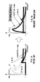
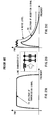
- the colored noise observed macroscopically in that way is noticed, and as shown in Fig.1B, the noise component N1 dominant in the low frequency band is positively canceled to shift the S/N value to plus, so that the extraction of a reception signal S buried in the low frequency band, with a comparatively high level, is attempted.
- the prevent invention realizes a noise canceling method and an apparatus therefor for interpolating a noise component based on a signal (hereinafter, occasionally referred to as specific signal) in which a time, an amplitude, and a phase are specified which is included into a received signal, and for canceling the noise component from the received signal.
- a signal hereinafter, occasionally referred to as specific signal
- the present invention realizes a noise canceling method and an apparatus therefor for periodically inserting a zero-point into a signal on a transmission side, for interpolating a noise component by using the zero-point on a reception side, and for subtracting the noise component from a received signal.
- Fig.2A shows a prior art transmission/reception system of a signal, in which a transmission signal from a transmission signal generator 32 is sent to a reception signal regenerator 33 through a Nyquist transmission line 31 as a transparent transmission line.
- an inserter (inserting portion) 1 of a specific signal or a zero-point (hereinafter, generally referred to as zero-point) is provided between the transmission signal generator 32 and the Nyquist transmission line 31 in such a transmission/reception system, and a noise canceler 2 is provided between the Nyquist transmission line 31 and the reception signal regenerator 33.
- the noise canceler 2 is composed of a frequency shift portion 3, a decimator (DCM) (decimating portion) 4, an interpolater (IPL) (interpolating portion) 5, a frequency reverse shift portion 6, and a subtracter (subtracting portion) 7, as described later.
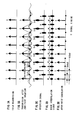
- the symbol rate of the transmission signal generated by the transmission signal generator 32 is assumed to be e.g. 192 kB as shown in Fig.3A. If such a transmission signal is provided to the zero-point inserter 1, the zero-point inserter 1 inserts the zero-point, as shown in Fig.3B, into the transmission signal of Fig.3A to be transmitted to the Nyquist transmission line 31. If the signal S is also transmitted at the same rate, the transmission rate assumes 384 kB.
- the reception side receives the reception signal S and the zero-point on which the noise N of the transmission line 31 is respectively put.
- the noise canceler 2 cancels the signal S including the noise N (S +N), and leaves only the noise N at the zero-point. Then, as shown in Fig.3D, a noise interpolation signal N' is generated at each reception signal point from the noises N on both sides.
- the noise canceler 2 further subtracts the noise interpolation signal N' shown in Fig.3D from the reception signal shown in Fig.3C, so that the noise N assumes N-N' as shown in Fig.3E.
- the signal (corresponding to the transmission signal), having substantially removed therefrom the noise, only composed of the signal component S can be regenerated.
- the above-mentioned transmission signal is firstly transmitted at the rate of 192 kB as shown in Fig.4A.
- the spectrum in this case is shown by the scalar, in which the abscissa denotes frequency bandwidth kHz, in the right of Fig.4A.
- the zero-points are inserted into such a transmission signal, the zero-points are to be inserted into signal points as shown in Fig.4B, so that the frequency bandwidth after the insertion assumes 384 kB. In this case, a spectrum is copied around +192 kHz can be obtained.
- the reception signal at the time when such a transmission signal into which the zero-points are inserted is transmitted to the reception side assumes the noise components N being overlapped with the signals S and the zero-points respectively, as shown in Fig.4C.
- the spectrum in this case is the same as that of the transmission signal shown in Fig.4B.
- the inverted signal in this case has a coefficient (-1) n because the inversion is made only to the signal component at the signal point.
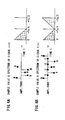
- decimation signal u(n) provided to the interpolater 5 shown in Fig.2B would exhibit the operations shown in Figs.6A and 6B.
- the signal u(n) from the decimator 4 is only composed of the noise component having the sample value and the spectrum shown in Fig.6A.
- the signal has the same transmission rate as the reception signal S(n) shown in Fig.5A and has only the noise component.
- the transmission signal into which the zero-points are inserted shown in Fig.4B can be obtained.
- Fig.7 shows how the noise component is canceled by paying attention only to the noise component.
- the transmission signal has the transmission bandwidth of 192 kB ( ⁇ 96 kB), and the zero-points are inserted thereto, the bandwidth is doubled, so that the copied component is generated to be sent to the Nyquist transmission line 31.
- the noise distribution firstly extends over ⁇ 192 kHz.
- the noise level is high especially in the left half of the frequency bandwidth of-192-0 kHz as shown in Figs. 1A and 1B, and is low in the frequency bandwidth of 0-+192 kHz.
- a noise component A+B will be shifted by +96 kHz for the noise characteristic 1 ⁇ , as shown in a noise characteristic 2 ⁇ .
- a noise component D in the noise characteristic 1 ⁇ will be aliased to -192 kHz--96 kHz.
- the noise bandwidth for which the interpolation (interpolated prediction) is desired to be performed is shifted to the interpolation bandwidth, thereby more effectively canceling the noise.
- the frequency becomes half. Therefore, the noise component A is aliased in +96-+192 kHz, the noise component B is aliased to-192--96 kHz, the noise component C is aliased to -96-0 kHz, and the noise component D is aliased to 0-+96 kHz.
- the bandwidth where the aliased component becomes the least is selected here.
- the interpolater 5 interpolates the zero-points and performs a filter canceling of the noise components A+C and B+D on both sides, the noise components A+C and B+D only between -96-+96 kHz remain as shown in a noise characteristic 4 ⁇ .
- the noise components A+C and B+D only between -192-0 kHz remain as shown in a noise characteristic 5 ⁇ .
- the subtracter 7 subtracts such noise components from the entire noise components shown in the characteristic 1 ⁇ thereby completely canceling the noise components A and B between-192-0 kHz as shown in a characteristic 6 ⁇ . It is to be noted that although the noise components C and D remain, their noise level is low, as shown in Fig.1B, so that the S/N value is not greatly influenced.
- the reception signal from which the noise is canceled in that way is regenerated substantially corresponding to the transmission signal.
- the reason for performing the frequency shift as mentioned above is because the interpolation bandwidth is set e.g. to the bandwidth where the most noises exist (in low frequency band in this example) to select the high frequency band with less noise for the aliased frequency bandwidth.
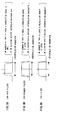
- Figs.8A-8E show various patterns of the zero-point insertion.
- Fig. 8A shows the case where the zero-points are inserted into every 4th signal S, whereby the interpolated noise bandwidth assumes 96 kHz.
- Fig.8B shows a case where the zero-points are inserted into every 3rd signal S, whereby the interpolated noise bandwidth assumes 128 kHz.
- Fig.8C shows a case where the zero-points are inserted into every other signal in the same way as the above-mentioned example, whereby the interpolated noise bandwidth assumes 192 kHz.
- Fig.8D shows an example in which two zero-points are inserted between the signals S, whereby the interpolated noise bandwidth assumes 256 kHz.
- Fig.8E shows an example in which three zero-points are inserted between signals S, whereby the interpolated noise bandwidth assumes 288 kHz.
- the system parameter may be optimized in order to effectively cancel the noise without decreasing the entire rate and attenuating the signal.
- an equalizer may be inserted at the former stage of the noise canceler.
- the inserted number of the zero-point is determined according to the decision result, and the number is notified to the transmission side, it becomes possible to adaptively change the zero-point inserted number.
- the zero-point insertion may be performed on the transmission side by using e.g. the PN (pseudo random) system.
- the reception side can interpolate the random noise by the PN system.
- the optimization may be performed according to the system characteristic.
- the interpolation 5 shown in Fig.2B can perform the interpolating operation by using various filter characteristics as shown in Figs.9A-9C.
- the interpolation bandwidth is made a transmission bandwidth.
- the filter has a characteristic that the number of taps is large and the cancelation range is small.
- the interpolation bandwidth is made the Nyquist bandwidth, and the filter has a characteristic that the number of taps is small, the cancelation range is large, but the aliasing waveform occurs outside the interpolated bandwidth.
- the interpolation bandwidth is also made the Nyquist bandwidth, and the filter has a characteristic that the number of taps is large, the calculation amount is much, and the aliasing waveform occurs outside the interpolation bandwidth.
- the above-mentioned frequency shift amount may be automatically determined for the frequency bandwidth by detecting the frequency bandwidth in which the noise frequency component of the received signal is large.
- an automatic equalizing process for removing the intersymbol interference at the former or latter stage of the noise cancelation may be performed.
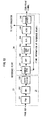
- Figs.10A and 10B show an embodiment of a modem using a noise canceling method and an apparatus therefor according to the present invention.
- a scramble process is performed to a transmission signal SD by a scrambler (SCR) 11, and a serial signal is converted into a parallel signal.
- the parallel signal is converted from a Gray code (G) of which the transmission signal is originally formed into a Natural code (N) by a vector sum circuit 12.
- G Gray code
- N Natural code
- a signal generator 13 transmits the transmission signal as shown in Figs.3A and 4A.
- the zero-points are inserted into the transmission signal by the zero-point inserter 1 according to the present invention, and the waveform is shaped by a roll-off filter (ROF) 14.
- ROF roll-off filter
- the output signal of the roll-off filter 14 is modulated by a modulation circuit (MOD) 15 and is further converted from the digital signal into the analog signal by a D/A conversion circuit 16. Then, a low-pass filter (LPF) 17 extracts a signal only in a low frequency bandwidth including a frequency bandwidth (10 kHz-450 kHz) of a power carrier wave to be transmitted to the transmission line.
- MOD modulation circuit
- LPF low-pass filter
- a predetermined frequency bandwidth component (10-450 kHz for a power carrier modem) is firstly extracted by a band-pass filter (BPF) 19, and then the analog signal is restored to the digital signal by an A/D conversion circuit 20.
- BPF band-pass filter
- the analog signal expressed in the digital form is demodulated into the baseband signal by a demodulation circuit (DEM) 21, so that the waveform is shaped by a roll-off filter 22.
- DEM demodulation circuit
- the output of the roll-off filter 22 is sent to a timing extractor 23 and a VCXO type PLL circuit 24, thereby extracting the phase of the zero-point signal and providing a sampling timing signal to the A/D converter 20.
- the noise component of the transmission line is canceled by the noise canceler 2 according to the present invention from the output signal of the roll-off filter 22, an intersymbol interference is removed by an equalizer (EQL) 25, and a phase adjustment is performed by a carrier automatic phase controller (CAPC) 26, so that a decision circuit (DEC) 27 further outputs a signal component from which the noise is removed.
- EQL equalizer
- CAC carrier automatic phase controller
- a vector difference (error) calculation by the Natural code, opposite to the vector sum circuit 12, is performed by the vector difference circuit 28, and the Natural code is restored to the Gray code, so that the parallel Gray code is converted into a serial signal by a descrambler (DSCR) 29 for the descramble process to be outputted as a reception signal RD.
- DSCR descrambler
- a transmission clock generation circuit (TX-CLK) 18 provides a transmission clock to the zero-point inserter 1 and the D/A converter 16, and distributes the same to other portions.
- a reception clock generation circuit (RX-CLK) 30 extracts the reception clock to be provided to the noise canceler 2 and the portions of the receiver.
- reception clock generation circuit 30 only passes the zero-point signal extracted from the PLL circuit 24. Also, the zero-point signal is a mere symbol timing signal in the prior art example.
- Fig.10A corresponds to a Nyquist transmission line 31 as a transparent transmission line.
- the Nyquist transmission line as shown in Fig.1B, transmits signals with the interval of the transmission signal points being the Nyquist interval (384 kB).
- Fig. 11 shows an embodiment of a noise canceler 2 shown in Fig.10A, which corresponds to the noise canceler 2 shown in Fig.2B.
- a received signal A (384 kB) is outputted as a signal C whose frequency is shifted by a desired rotation vector signal B by the frequency shift portion 3.
- the signal C is sent to the decimator 4, where the signal is converted into a signal D (192 kB) having only the noise component shown in Fig.5D, based on the zero-point signal (192 kB) extracted from the PLL circuit 24 shown in Fig.10A.
- the signal D is sent to the interpolater 5 to be outputted as a signal E (384 kB) interpolated by the filter process. Since the signal E is sent to the frequency reverse shift portion 6 and shifted toward the reverse direction to the rotation vector signal B used by the frequency shift portion 3, the signal is rotated in the reverse direction by a signal F composing a conjugated complex number with the signal B to be outputted as a signal G. It is to be noted that a delay circuit 8 is provided on the course in order that the signal F is adjusted to the timing of the output signal of the interpolater 5.
- the output signal G of the frequency reverse shift portion 6 is subtracted from the received signal A by the subtracter 7 to assume an output signal K. It is to be noted that a delay circuit 9 is also provided to the received signal A in order to adjust the timing to the output signal of the interpolater 5 in this case.
- the signal K that is the received signal A from which the noise component is canceled is outputted.
- Fig. 12 shows an embodiment of the interpolater 5 shown in Fig.11, which is composed of a zero-point inserter 51 and an interpolation filter 52.
- the zero-point inserter 51 inserts the zero-points between the noises, as shown in Fig.6B, with respect to the signal D (192 kB) composed of only the noise component outputted from the decimator 4 to be provided to the interpolation filter 52 as a signal of 384 kB transmission bandwidth.
- the interpolation filter 52 can be composed of a transversal filter, which can compose various filters as shown in Figs.9A-9C with a delay circuit 521 and filter coefficients C1-Cn of a multiplication circuit 522.
- the interpolation signal E outputted therefrom is outputted as a signal having a certain amplitude where the noise component N' at each zero-point is interpolated by the noise components N on both sides of the zero-point at the signal shown in Fig.3D.
- Fig.13 shows an embodiment of the timing extractor 23 and the VCXO type PLL circuit 24 shown in Fig.10A.
- the timing extractor 23 is composed of a power calculation circuit (PWR) 231, a band-pass filter 232, and a vectorizing circuit 233.
- the PLL circuit 24 is composed of a comparator 241, a low-pass filter 242, a secondary PLL circuit 243, a D/A conversion circuit 244, a VCXO (Voltage Controlled Crystal Oscillator) circuit 245, and a frequency divider 246.
- PWR power calculation circuit
- the PLL circuit 24 is composed of a comparator 241, a low-pass filter 242, a secondary PLL circuit 243, a D/A conversion circuit 244, a VCXO (Voltage Controlled Crystal Oscillator) circuit 245, and a frequency divider 246.
- VCW Voltage Controlled Crystal Oscillator
- the vector signal outputted from the roll-off filter 22 is squared by the power calculation circuit 231 to calculate the power.
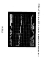
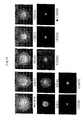
- the spectrum at this time is shown in Fig.14, where the line spectrum in the center of the photograph indicates the zero-point signal of 192 kHz. Namely, since the zero-point is periodically transmitted on the transmission side, the energy for this section is zero, whereas it becomes possible to extract the power spectrum according to the insertion degree of the zero-point.
- the power value thus obtained is passed through the band-pass filter 232. Since the band-pass filter having the center frequency of 192 kHz is used in this example, desired zero-point signal information is outputted to the vectorizing circuit 233.
- the vectorizing circuit 233 vectorizes the input signal by synthesizing the input signal with a signal whose phase is different by 90 degrees, and provides the same to the PLL circuit 24 as timing phase information.
- the timing phase information from the vectorizing circuit 233 is firstly compared with the phase of a reference point preliminarily known at the comparator 241.
- the phase difference is filtered to include only a low component by the low-pass filter 242, so that the controlled voltage of the VCXO 245 is controlled by the secondary PLL circuit 243 composed of two integrators and the D/A conversion circuit 244.
- phase information is fed back to the comparator 241 to be compared with the phase at the reference point.
- the phase difference between the timing phase information from the vectorizing circuit 233 and the reference point is pulled in or nullified thereby enabling the extraction of the zero-point signal whose synchronization is established.
- the sample timing signal to the A/D converter 16 is outputted from the VCXO circuit 245, and is finally fed back to the comparator 241 to compose a phase locked loop.
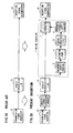
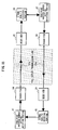
- Figs.8A-8E various embodiments as shown in Figs.8A-8E can be taken into account in the above embodiment. Namely, it is not necessary to fix this zero-point interval, but it is possible to control the zero-point interval as shown in Fig. 15.
- a deciding portion 36 for deciding the signal quality by the output signal from the receiver 35 is provided. If the decision result is provided to a zero-point inserted number setting/notifying portion 37, which determines the zero-point inserted number, and notifies the information to a zero-point inserted number setting/notifying portion 41 through the transmission line 31b to set the zero-point number of the transmitter 34.
- the signal quality is decided by a signal quality deciding portion 40 provided in the same way as the signal quality deciding portion 36, based on the signal received by the receiver 39 from the transmitter 38 through the transmission line 31b. If the zero-point inserted number setting/notifying portion 41 determines the zero-point inserted number based on the decision result and notifies the same to the transmitter 38, this transmitter 38 also performs the insertion control of the zero-point in the same way as the transmitter 34.
- the zero-point interval as shown in Figs.8A-8E can be adaptively changed based on the signal quality of the transmission line.
- the above-mentioned frequency shift portion 3, as shown in Fig.11, provides the fixed rotation vector signal B. However, it is also possible to automatically change this vector signal.
- Fig.16 shows an arrangement of such an automatic frequency shift, in which multipliers 42 and 43, decimators 44 and 45, FFT calculators (operating unit) 46 and 47, and a shift amount determining portion 48 are additionally provided in the noise canceler 2 in Fig.11.
- carrier signals ⁇ f1 and ⁇ f2 where the frequencies of the outputs from the roll-off filter 22 are respectively shifted by 90 degrees mutually by the multipliers 42 and 43, are multiplied, and are respectively decimated to obtain the signals of the rate 192 kB at the decimators 44 and 45. Then, the signals are converted into the frequency signals by the FFT calculators 46 and 47, and determines which frequency bandwidth has the largest noise bandwidth at the frequency shift amount determining portion 48, so that the determined frequency shift amount is provided to the frequency shift portion 3.
- the reason for using two FFT calculators is because the frequency bandwidth of the input signal is 192 kB, a half of the whole bandwidth.
- Fig. 17 shows a noise reduction state in case where the frequency shift amount is variously shifted. In this case, it is found that the reduction effect is the largest over the range of 128 kHz-224 kHz.
- the baseband signal bandwidth at the time when the signal of such a transmission bandwidth is outputted from the roll-off filter 22 of the modem shown in Fig.10A is shown in Fig.18B.
- the bandwidth of ⁇ 192 kHz around 0 kHz can be obtained.
- 10 kHz-174 kHz in Fig.18A corresponds to-220 kHz--56 kHz in Fig.18B.
- the noise canceler 2 of the present invention inputs the output signal of the roll-off filter 22 as it is.
- an equalizer (EQL) 33 is provided on the output side (former stage of noise canceler 2) of a demodulator/roll-off filter (DEM/ROF) 21 (corresponding to filter 22 in Fig.10A) as in a modification shown in Fig.19, and the intersymbol interference is preliminarily removed, it becomes possible to perform a more effective noise cancelation.
- the equalizing process is divided so that the equalizer 33 may perform a time equalization, for example, and the equalizer 25 may perform a frequency equalization, for example.
- time equalization and the frequency equalization are known for an equalizer in the ADSL field, a quite large effect can be achieved by the time axis equalization alone.
- a noise canceling method and an apparatus therefor is arranged so that a signal in which a time axis, an amplitude, and a phase are specified or a zero-point signal is inserted into a transmission signal, a noise component is interpolated by using the specified signal or the zero-point signal, and an originally transmitted signal is regenerated by subtracting the noise component from a received signal. Therefore, it becomes possible to realize a high-speed data transmission by an effective noise cancelation in a low frequency band with less signal attenuation, even in circumstances with a number of noises, especially in a state where the S/N value is minus such as in a power-line carrier.
- a noise canceling method and an apparatus therefor can be similarly applied not only to the power-line carrier modem, but also to the CATV modem, the ADSL modem, the VDSL modem, the 2.4G wireless LAN, the wireless transmission field, and the optical transmission field.
- the high recording density can be realized for a signal buried in the noise due to the enhanced speed such as a magnetic disk by accurately taking out the signal.
- a noise canceling method and an apparatus therefor can be applied to a process of taking out the signal from the noise in the multi-valued transmission technology of semiconductors, and can contribute to the enhanced speed of the semiconductor performance. Furthermore, the application to the fields troubled by various noises such as in the voice recognition, the image compression, the demodulation of the bar code scanner, and the like is made possible.
Landscapes
- Engineering & Computer Science (AREA)
- Computer Networks & Wireless Communication (AREA)
- Signal Processing (AREA)
- Noise Elimination (AREA)
- Digital Transmission Methods That Use Modulated Carrier Waves (AREA)
Abstract
Description
- Power-line carrier modem field which attempts to realize a data transmission at a high speed under circumstances with many noises such as in a power-line carrier;
- CATV modem, ADSL modem, VDSL modem, 2.4G wireless LAN, wireless transmission field, optical transmission field, and the like;
- Magnetic disk or optical disk which attempts to realize a high recording density by taking out such a signal as is buried in the noise due to the transmission rate accelerated;
- Semiconductor of accelerated multi valued transmission technology;
- Voice recognition, image compression, demodulation of bar code scanner, and the like under noisy circumstances.
Claims (24)
- A noise canceling method comprising the steps of:interpolating a noise component based on a signal in which a time, an amplitude, and a phase are specified which is included into a received signal, andcanceling the noise component from the received signal.
- A noise canceling method comprising the steps of:periodically inserting a zero-point into a signal on a transmission side,interpolating a noise component by using the zero-point on a reception side, andsubtracting the noise component from a received signal.
- The noise canceling method as claimed in claim 2 wherein one or more zero-points are inserted at intervals of an integer number of samples.
- The noise canceling method as claimed in claim 3 wherein an inserted number of the zero-points is determined by deciding a signal quality on the reception side to be notified to the transmission side.
- The noise canceling method as claimed in any one of claims 1 to 4 wherein a transmission line of the received signal comprises a transparent transmission line.
- The noise canceling method as claimed in claim 5 wherein the transparent transmission line comprises a Nyquist transmission line.
- The noise canceling method as claimed in claim 1 or 2 wherein the step of interpolating includes steps of performing a frequency shift of the received signal to a desired frequency bandwidth, decimating according to the zero-point, performing an interpolation, and finally performing the frequency shift in a reverse direction so as to adjust to the original signal, thereby generating the noise component of the received signal.
- The noise canceling method as claimed in claim 7 wherein for the step of interpolating, a zero-point is inserted into the decimated signal, and a low-pass filter process for making an interpolation bandwidth a transmission bandwidth is further performed.
- The noise canceling method as claimed in claim 8 wherein the low-pass filter process comprises a cos-squared filter process for making the interpolation bandwidth a Nyquist bandwidth.
- The noise canceling method as claimed in claim 8 wherein the low-pass filter process comprises a cos filter process for making the interpolation bandwidth a Nyquist bandwidth.
- The noise canceling method as claimed in claim 7 wherein a frequency bandwidth, in which a noise frequency component is large, is detected in the received signal so that the frequency shift amount is automatically determined for the frequency bandwidth.
- The noise canceling method as claimed in any one of claims 1 to 11 wherein an automatic equalizing process is further performed so as to remove an intersymbol interference at a former or latter stage of a noise cancelation.
- A noise canceling apparatus comprising:means for interpolating a noise component from a received signal including a signal in which a time, an amplitude, and a phase are specified, andmeans for canceling the noise component from the received signal.
- A noise canceling apparatus comprising:means for periodically inserting a zero-point into a signal on a transmission side,means for interpolating a noise component of a received signal by using the zero-point on a reception side, andmeans for subtracting the noise component from the received signal.
- The noise canceling apparatus as claimed in claim 14 wherein one or more zero-points are inserted at intervals of an integer number of samples.
- The noise canceling apparatus as claimed in claim 15 wherein an inserted number of the zero-points is determined by deciding a signal quality on the reception side to be notified to the transmission side.
- The noise canceling apparatus as claimed in any one of claims 13 to 16 wherein a transmission line of the received signal comprises a transparent transmission line.
- The noise canceling apparatus as claimed in claim 17 wherein the transparent transmission line comprises a Nyquist transmission line.
- The noise canceling apparatus as claimed in claim 13 or 14 wherein the means for interpolating include means for performing a frequency shift to the received signal to a desired frequency bandwidth, means for decimating according to the zero-point thereafter, means for further performing an interpolation, and means for performing the frequency shift in a reverse direction so as to adjust to the original signal, thereby generating the noise component of the received signal.
- The noise canceling apparatus as claimed in claim 19 wherein the interpolation means include a circuit for inserting zero-points into the decimated signal, and further include a low-pass filter for making an interpolation bandwidth a transmission bandwidth.
- The noise canceling apparatus as claimed in claim 20 wherein the low-pass filter comprises a cos-squared filter for making the interpolation bandwidth a Nyquist bandwidth.
- The noise canceling apparatus as claimed in claim 20 wherein the low-pass filter comprises a cos filter for making the interpolation bandwidth a Nyquist bandwidth.
- The noise canceling apparatus as claimed in claim 19 wherein the means for performing the frequency shift include means for detecting a frequency bandwidth, in which a noise frequency component is large, in the received signal so that the frequency shift amount is automatically determined for the frequency bandwidth.
- The noise canceling apparatus as claimed in any one of claims 1 to 23 wherein an automatic equalizer is further provided for removing an intersymbol interference at a former or latter stage of a noise cancelation.
Applications Claiming Priority (2)
| Application Number | Priority Date | Filing Date | Title |
|---|---|---|---|
| JP2000359949A JP3385266B2 (en) | 2000-11-27 | 2000-11-27 | Noise removal method and apparatus |
| JP2000359949 | 2000-11-27 |
Publications (2)
| Publication Number | Publication Date |
|---|---|
| EP1227597A2 true EP1227597A2 (en) | 2002-07-31 |
| EP1227597A3 EP1227597A3 (en) | 2004-01-28 |
Family
ID=18831626
Family Applications (1)
| Application Number | Title | Priority Date | Filing Date |
|---|---|---|---|
| EP01107438A Withdrawn EP1227597A3 (en) | 2000-11-27 | 2001-03-27 | Noise cancelling method and apparatus |
Country Status (6)
| Country | Link |
|---|---|
| US (2) | US7110465B2 (en) |
| EP (1) | EP1227597A3 (en) |
| JP (1) | JP3385266B2 (en) |
| KR (1) | KR100655345B1 (en) |
| CN (1) | CN1198400C (en) |
| TW (1) | TW522665B (en) |
Cited By (3)
| Publication number | Priority date | Publication date | Assignee | Title |
|---|---|---|---|---|
| RU2244386C2 (en) * | 2003-03-28 | 2005-01-10 | Корпорация "Самсунг Электроникс" | Method and device for recovering audio-signal high-frequency component |
| RU2257671C1 (en) * | 2003-12-09 | 2005-07-27 | Федеральное государственное унитарное предприятие Воронежский научно-исследовательский институт "Вега" | Digital narrow-band signals detector |
| EP1333608A3 (en) * | 2002-01-31 | 2006-03-29 | Fujitsu Limited | Data transmission system and data transmission method for cable television |
Families Citing this family (27)
| Publication number | Priority date | Publication date | Assignee | Title |
|---|---|---|---|---|
| JP3427381B2 (en) * | 2001-06-20 | 2003-07-14 | 富士通株式会社 | Noise cancellation method and apparatus |
| RU2210858C2 (en) * | 2001-10-08 | 2003-08-20 | Дунаев Игорь Борисович | Method for noise-immune data transmission |
| DE60205128T2 (en) * | 2001-10-19 | 2006-05-24 | Matsushita Electric Industrial Co., Ltd., Kadoma | DEVICE AND METHOD FOR SPREADING SPECTRUM TRANSMISSION |
| JP3695586B2 (en) * | 2002-06-25 | 2005-09-14 | 三菱電機株式会社 | Receiver |
| JP3927463B2 (en) * | 2002-07-30 | 2007-06-06 | トヨタ自動車株式会社 | Digital signal processing receiver |
| US7489747B2 (en) * | 2003-02-21 | 2009-02-10 | Xocyst Transfer Ag L.L.C. | Decision directed flicker noise cancellation |
| US7042967B2 (en) * | 2003-03-03 | 2006-05-09 | Interdigital Technology Corporation | Reduced complexity sliding window based equalizer |
| JP4438482B2 (en) | 2004-04-05 | 2010-03-24 | ソニー・エリクソン・モバイルコミュニケーションズ株式会社 | Reception quality estimation method and apparatus |
| US20070278881A1 (en) * | 2004-09-08 | 2007-12-06 | Nobuyoshi Yamashita | Shaft Member For Hydrodynamic Bearing Apparatuses And A Method For Producing The Same |
| JP3747415B1 (en) * | 2005-05-11 | 2006-02-22 | 株式会社ネットインデックス | Multiplex transmission apparatus and multiple transmission method |
| WO2007015317A1 (en) * | 2005-08-02 | 2007-02-08 | Sumitomo Electric Industries, Ltd. | Transmitter, receiver, communication method and transmitting/receiving system |
| EP2086116A3 (en) * | 2008-01-31 | 2013-10-16 | ST Wireless SA | Method and arrangement for signal processing in a receiver that can be tuned to different carriers |
| US7515703B1 (en) | 2008-05-19 | 2009-04-07 | International Business Machines Corporation | Method and system for determining conference call embellishment tones and transmission of same |
| US8622302B2 (en) * | 2009-03-17 | 2014-01-07 | Datalogic ADC, Inc. | Systems and methods for compensating for fixed pattern noise |
| US8737636B2 (en) | 2009-07-10 | 2014-05-27 | Qualcomm Incorporated | Systems, methods, apparatus, and computer-readable media for adaptive active noise cancellation |
| CN101667426A (en) * | 2009-09-23 | 2010-03-10 | 中兴通讯股份有限公司 | Device and method for eliminating environmental noise |
| US20120281687A1 (en) * | 2010-02-01 | 2012-11-08 | Nec Corporation | Wireless base station, transmission method, and program |
| EP2355432A1 (en) * | 2010-02-05 | 2011-08-10 | Nokia Siemens Networks Oy | Method and arrangement for transmitting an orthogonal frequency diversity multiplex signal via at least one optical filter |
| US9634720B2 (en) | 2013-07-05 | 2017-04-25 | Sony Corporation | Apparatuses and a method for crosstalk estimations |
| US9591498B1 (en) * | 2014-06-25 | 2017-03-07 | Sprint Communications Company L.P. | Detection of base station synchronization failure |
| US9565646B1 (en) | 2014-06-25 | 2017-02-07 | Sprint Communications Company L.P. | Detection of base station synchronization failure |
| US9258153B1 (en) * | 2014-11-28 | 2016-02-09 | Keysight Technologies, Inc. | Inter-symbol interference (ISI) loss filter device |
| US9786262B2 (en) | 2015-06-24 | 2017-10-10 | Edward Villaume | Programmable noise reducing, deadening, and cancelation devices, systems and methods |
| CN106059623B (en) * | 2016-05-25 | 2019-09-06 | 深圳市佳联智控电子科技有限公司 | A kind of implementation method of power line carrier, PLC |
| WO2019167140A1 (en) * | 2018-02-27 | 2019-09-06 | 三菱電機株式会社 | Radio communication system and interference suppression method |
| US10763976B1 (en) * | 2019-03-13 | 2020-09-01 | Rohde & Schwarz Gmbh & Co. Kg | Digital low frequency correction circuit and method for reducing low frequency disturbances within a digital signal |
| CA3164466C (en) | 2019-12-13 | 2023-11-28 | Zte Corporation | Time-domain modulation scheme for low peak average power ratio |
Family Cites Families (12)
| Publication number | Priority date | Publication date | Assignee | Title |
|---|---|---|---|---|
| JP2763982B2 (en) | 1992-03-13 | 1998-06-11 | 富士通株式会社 | Transmission signal processing method |
| US5583889A (en) * | 1994-07-08 | 1996-12-10 | Zenith Electronics Corporation | Trellis coded modulation system for HDTV |
| JPH09116461A (en) * | 1995-10-18 | 1997-05-02 | Katsuyoshi Azeyanagi | Method and apparatus for separating and estimating noise included in spread spectrum signal |
| US6215798B1 (en) * | 1996-11-01 | 2001-04-10 | Telefonaktiebolaget Lm Ericsson (Publ) | Multi-frame synchronization for parallel channel transmissions |
| DE19646164A1 (en) * | 1996-11-08 | 1998-05-14 | Deutsche Telekom Ag | Process for the transmission of digital signals |
| JP2998794B2 (en) | 1997-01-28 | 2000-01-11 | 日本電気株式会社 | Periodic noise removing apparatus and periodic noise removing method |
| CA2302370C (en) * | 1997-09-04 | 2004-06-01 | Silicon Image, Inc. | System and method for high-speed, synchronized data communication |
| JP3568182B2 (en) | 1997-12-03 | 2004-09-22 | 株式会社日立国際電気 | Data transmission device synchronization detection method and device |
| AU3218699A (en) * | 1998-03-30 | 1999-10-18 | 3Com Corporation | Low complexity frequency estimator and interference cancellation method and device |
| US6426983B1 (en) * | 1998-09-14 | 2002-07-30 | Terayon Communication Systems, Inc. | Method and apparatus of using a bank of filters for excision of narrow band interference signal from CDMA signal |
| JP3084368B1 (en) | 1999-03-30 | 2000-09-04 | 株式会社次世代デジタルテレビジョン放送システム研究所 | OFDM receiver |
| JP3675670B2 (en) | 1999-05-27 | 2005-07-27 | パイオニア株式会社 | Receiver |
-
2000
- 2000-11-27 JP JP2000359949A patent/JP3385266B2/en not_active Expired - Fee Related
-
2001
- 2001-03-27 EP EP01107438A patent/EP1227597A3/en not_active Withdrawn
- 2001-03-28 US US09/819,395 patent/US7110465B2/en not_active Expired - Fee Related
- 2001-11-22 KR KR1020010072919A patent/KR100655345B1/en not_active Expired - Fee Related
- 2001-11-26 TW TW090129187A patent/TW522665B/en not_active IP Right Cessation
- 2001-11-27 CN CNB011394757A patent/CN1198400C/en not_active Expired - Fee Related
-
2006
- 2006-07-25 US US11/492,523 patent/US20060256890A1/en not_active Abandoned
Cited By (3)
| Publication number | Priority date | Publication date | Assignee | Title |
|---|---|---|---|---|
| EP1333608A3 (en) * | 2002-01-31 | 2006-03-29 | Fujitsu Limited | Data transmission system and data transmission method for cable television |
| RU2244386C2 (en) * | 2003-03-28 | 2005-01-10 | Корпорация "Самсунг Электроникс" | Method and device for recovering audio-signal high-frequency component |
| RU2257671C1 (en) * | 2003-12-09 | 2005-07-27 | Федеральное государственное унитарное предприятие Воронежский научно-исследовательский институт "Вега" | Digital narrow-band signals detector |
Also Published As
| Publication number | Publication date |
|---|---|
| TW522665B (en) | 2003-03-01 |
| KR20020041286A (en) | 2002-06-01 |
| EP1227597A3 (en) | 2004-01-28 |
| US20060256890A1 (en) | 2006-11-16 |
| US20020064234A1 (en) | 2002-05-30 |
| JP3385266B2 (en) | 2003-03-10 |
| JP2002164801A (en) | 2002-06-07 |
| US7110465B2 (en) | 2006-09-19 |
| CN1198400C (en) | 2005-04-20 |
| CN1374762A (en) | 2002-10-16 |
| KR100655345B1 (en) | 2006-12-08 |
Similar Documents
| Publication | Publication Date | Title |
|---|---|---|
| US7110465B2 (en) | Noise canceling method and apparatus | |
| JP3427381B2 (en) | Noise cancellation method and apparatus | |
| JP3407253B2 (en) | Peak suppression method and data transmission device | |
| EP1341332A1 (en) | Data transmission method and apparatus | |
| WO2010042350A1 (en) | Adaptive frequency-domain reference noise canceller for multicarrier communications systems | |
| WO1997050188A1 (en) | Asymmetric digital subscriber loop transceiver and method | |
| EP1271873A2 (en) | Interleaving in multicarrier transmission | |
| JP3986929B2 (en) | Leakage electromagnetic field suppression transmission method and leakage electromagnetic field suppression transmission apparatus in power line carrier communication | |
| EP1333593A1 (en) | Power line transmission technical | |
| JP3421027B2 (en) | Synchronization method and device | |
| JP3691480B2 (en) | Noise removal method and apparatus | |
| Nedic | An unified approach to equalization and echo cancellation in OQAM-based multi-carrier data transmission | |
| JP3644021B2 (en) | Noise removal method and apparatus |
Legal Events
| Date | Code | Title | Description |
|---|---|---|---|
| PUAI | Public reference made under article 153(3) epc to a published international application that has entered the european phase |
Free format text: ORIGINAL CODE: 0009012 |
|
| AK | Designated contracting states |
Kind code of ref document: A2 Designated state(s): AT BE CH CY DE DK ES FI FR GB GR IE IT LI LU MC NL PT SE TR |
|
| AX | Request for extension of the european patent |
Free format text: AL;LT;LV;MK;RO;SI |
|
| PUAL | Search report despatched |
Free format text: ORIGINAL CODE: 0009013 |
|
| AK | Designated contracting states |
Kind code of ref document: A3 Designated state(s): AT BE CH CY DE DK ES FI FR GB GR IE IT LI LU MC NL PT SE TR |
|
| AX | Request for extension of the european patent |
Extension state: AL LT LV MK RO SI |
|
| RIC1 | Information provided on ipc code assigned before grant |
Ipc: 7H 04B 3/54 B Ipc: 7H 04B 1/10 A |
|
| 17P | Request for examination filed |
Effective date: 20040217 |
|
| AKX | Designation fees paid |
Designated state(s): DE FR GB |
|
| STAA | Information on the status of an ep patent application or granted ep patent |
Free format text: STATUS: THE APPLICATION HAS BEEN WITHDRAWN |
|
| 18W | Application withdrawn |
Effective date: 20090126 |