EP1227533A2 - Secondary battery device and method of protecting an overdischarge of the same - Google Patents
Secondary battery device and method of protecting an overdischarge of the same Download PDFInfo
- Publication number
- EP1227533A2 EP1227533A2 EP02001697A EP02001697A EP1227533A2 EP 1227533 A2 EP1227533 A2 EP 1227533A2 EP 02001697 A EP02001697 A EP 02001697A EP 02001697 A EP02001697 A EP 02001697A EP 1227533 A2 EP1227533 A2 EP 1227533A2
- Authority
- EP
- European Patent Office
- Prior art keywords
- secondary battery
- state
- load circuit
- load
- overdischarge
- Prior art date
- Legal status (The legal status is an assumption and is not a legal conclusion. Google has not performed a legal analysis and makes no representation as to the accuracy of the status listed.)
- Withdrawn
Links
- 238000000034 method Methods 0.000 title claims description 7
- 230000001681 protective effect Effects 0.000 claims abstract description 20
- 230000002950 deficient Effects 0.000 description 7
- 230000001413 cellular effect Effects 0.000 description 5
- 238000004891 communication Methods 0.000 description 4
- 239000000725 suspension Substances 0.000 description 4
- 238000001514 detection method Methods 0.000 description 3
- HBBGRARXTFLTSG-UHFFFAOYSA-N Lithium ion Chemical compound [Li+] HBBGRARXTFLTSG-UHFFFAOYSA-N 0.000 description 2
- 238000000354 decomposition reaction Methods 0.000 description 2
- 230000006866 deterioration Effects 0.000 description 2
- 238000010586 diagram Methods 0.000 description 2
- 239000003792 electrolyte Substances 0.000 description 2
- 229910001416 lithium ion Inorganic materials 0.000 description 2
- 230000003449 preventive effect Effects 0.000 description 2
- 230000002159 abnormal effect Effects 0.000 description 1
- 230000000694 effects Effects 0.000 description 1
- 238000012986 modification Methods 0.000 description 1
- 230000004048 modification Effects 0.000 description 1
- 239000005486 organic electrolyte Substances 0.000 description 1
Images


Classifications
-
- H—ELECTRICITY
- H01—ELECTRIC ELEMENTS
- H01M—PROCESSES OR MEANS, e.g. BATTERIES, FOR THE DIRECT CONVERSION OF CHEMICAL ENERGY INTO ELECTRICAL ENERGY
- H01M10/00—Secondary cells; Manufacture thereof
- H01M10/42—Methods or arrangements for servicing or maintenance of secondary cells or secondary half-cells
- H01M10/44—Methods for charging or discharging
-
- G—PHYSICS
- G01—MEASURING; TESTING
- G01R—MEASURING ELECTRIC VARIABLES; MEASURING MAGNETIC VARIABLES
- G01R19/00—Arrangements for measuring currents or voltages or for indicating presence or sign thereof
- G01R19/165—Indicating that current or voltage is either above or below a predetermined value or within or outside a predetermined range of values
- G01R19/16533—Indicating that current or voltage is either above or below a predetermined value or within or outside a predetermined range of values characterised by the application
- G01R19/16538—Indicating that current or voltage is either above or below a predetermined value or within or outside a predetermined range of values characterised by the application in AC or DC supplies
- G01R19/16542—Indicating that current or voltage is either above or below a predetermined value or within or outside a predetermined range of values characterised by the application in AC or DC supplies for batteries
-
- G—PHYSICS
- G01—MEASURING; TESTING
- G01R—MEASURING ELECTRIC VARIABLES; MEASURING MAGNETIC VARIABLES
- G01R31/00—Arrangements for testing electric properties; Arrangements for locating electric faults; Arrangements for electrical testing characterised by what is being tested not provided for elsewhere
- G01R31/36—Arrangements for testing, measuring or monitoring the electrical condition of accumulators or electric batteries, e.g. capacity or state of charge [SoC]
- G01R31/3644—Constructional arrangements
- G01R31/3648—Constructional arrangements comprising digital calculation means, e.g. for performing an algorithm
-
- G—PHYSICS
- G01—MEASURING; TESTING
- G01R—MEASURING ELECTRIC VARIABLES; MEASURING MAGNETIC VARIABLES
- G01R31/00—Arrangements for testing electric properties; Arrangements for locating electric faults; Arrangements for electrical testing characterised by what is being tested not provided for elsewhere
- G01R31/36—Arrangements for testing, measuring or monitoring the electrical condition of accumulators or electric batteries, e.g. capacity or state of charge [SoC]
- G01R31/396—Acquisition or processing of data for testing or for monitoring individual cells or groups of cells within a battery
-
- Y—GENERAL TAGGING OF NEW TECHNOLOGICAL DEVELOPMENTS; GENERAL TAGGING OF CROSS-SECTIONAL TECHNOLOGIES SPANNING OVER SEVERAL SECTIONS OF THE IPC; TECHNICAL SUBJECTS COVERED BY FORMER USPC CROSS-REFERENCE ART COLLECTIONS [XRACs] AND DIGESTS
- Y02—TECHNOLOGIES OR APPLICATIONS FOR MITIGATION OR ADAPTATION AGAINST CLIMATE CHANGE
- Y02E—REDUCTION OF GREENHOUSE GAS [GHG] EMISSIONS, RELATED TO ENERGY GENERATION, TRANSMISSION OR DISTRIBUTION
- Y02E60/00—Enabling technologies; Technologies with a potential or indirect contribution to GHG emissions mitigation
- Y02E60/10—Energy storage using batteries
-
- Y—GENERAL TAGGING OF NEW TECHNOLOGICAL DEVELOPMENTS; GENERAL TAGGING OF CROSS-SECTIONAL TECHNOLOGIES SPANNING OVER SEVERAL SECTIONS OF THE IPC; TECHNICAL SUBJECTS COVERED BY FORMER USPC CROSS-REFERENCE ART COLLECTIONS [XRACs] AND DIGESTS
- Y10—TECHNICAL SUBJECTS COVERED BY FORMER USPC
- Y10S—TECHNICAL SUBJECTS COVERED BY FORMER USPC CROSS-REFERENCE ART COLLECTIONS [XRACs] AND DIGESTS
- Y10S320/00—Electricity: battery or capacitor charging or discharging
- Y10S320/13—Fault detection
Definitions
- the present invention relates to a secondary battery device comprising an overdischarge protective unit and a method of protecting an overdischarge of the secondary battery.
- a secondary battery device comprises, e.g., a plurality of unit batteries connected in series.
- some of the unit batteries can be overcharged or overdischarged due to variation of the capacity or internal impedance of the unit batteries. For example, when a lithium ion battery as a unit battery is overcharged beyond a tolerance voltage, the decomposition reaction of an organic electrolyte proceeds. On the contrary, when the lithium ion battery is overdischarged, it shows an increase of internal resistance or the like, causing the deterioration of performance or safety thereof.
- a battery device normally comprises a protective circuit incorporated therein.
- the group of unit batteries is electrically connected to an external circuit, such as load and charger, through the protective circuit.
- the protective circuit individually detects the terminal voltage of each of the unit batteries. When one of the unit batteries shows a terminal voltage of higher than a predetermined reference voltage, the protective circuit causes an FET element or the like to disconnect the battery device from the external circuit so that charge or discharge is forced to suspend. Therefore, the overcharge and overdischarge can be prevented, thereby protecting the unit batteries.
- a potable personal computer or the like is subject to defectives, such as troubles in hard disk, when the power supply is forced to be turned off while CPU is in a predetermined operation state, such as reading of data. Such a forced suspension of discharge should be avoided as much as possible. It is inconvenient also for cellular phone that the power supply is forced to be turned off during communication.
- the protective circuit causes the suspension of discharge to an apparatus such as main body of personal computer to prevent one of the unit batteries from being overdischarged, even if the total battery voltage of the secondary battery device falls within a normal range which allows the supply of electric power high enough to operate the apparatus.
- the power supply can be forced to be turned off even when CPU of personal computer is in a predetermined operation state or cellular phone is communicating.
- the unit batteries be protected against overdischarge or the like.
- the continuation of predetermined operation state of load should be given priority.
- An object of the invention is to provide a secondary battery device and a method of protecting an overdischarge of the secondary battery, which is subject as little as possible to defectives, such as disconnection of power supply in a predetermined operation state of load.
- the secondary battery device comprises a secondary battery, a load state judging unit, and an overdischarge protective unit connected to the secondary battery.
- the secondary battery supplies electric power into a load circuit.
- the load state judging unit judges the operation state of the load circuit.
- the overdischarge protective unit detects the discharged state of the secondary battery, and breaks the discharge from the secondary battery when the secondary battery reaches a predetermined discharged state.
- the load state judging unit judges the load circuit stays in a predetermined operation state requiring the protection of power supply, the supply of electric power into the load circuit is allowed to continue without breaking the discharge from the secondary battery.
- the "a predetermined operation state of the load circuit requiring the protection of power supply” as used herein may be set to stay in any of the following states (1), (2).
- the predetermined operation state of the load circuit may be arbitrarily set by the user or may be previously fixed to the definite conditions by the manufacturer.
- the overdischarge protective unit allows the supply of electric power into the load circuit to continue without breaking the discharge from the secondary battery when the load state judging unit judges that the load circuit stays in the predetermined operation state requiring the protection of power supply. Accordingly, the occurrence of defectives such as sudden disconnection of power supply can be prevented as much as possible when the load circuit stays in the predetermined operation state requiring the protection of power supply, such as state where the hard disk of personal computer is driven or communicating state of cellular phone.
- the risk of overdischarging to an extent such that the terminal voltage of the secondary battery falls below a predetermined reference voltage can be eliminated by providing the secondary battery device with an overdischarge preventive function on the load circuit side thereof.
- the secondary battery device may be overdischarged when the load circuit stays in a predetermined operation state. However, it is thought that the load circuit stays in a predetermined operation state requiring the protection of power supply for a short period of time. Accordingly, the operation of the load circuit is normally terminated as early as possible by the use of a mechanism which informs the exterior of the fact that the secondary battery is overdischarged. For example, the mechanism informs to the exterior by means of displaying on the display of the personal computer or sounding an alarm. By doing so, the secondary battery device cannot reach an abnormal state developed by the continuation of overdischarge and thus can be recovered to its normal terminal voltage after being charged.
- the secondary battery may be a plurality of unit batteries connected in series.
- the unit battery includes not only a single battery cell but also a plurality of battery cells connected in parallel.
- a secondary battery device comprises a secondary battery, a load state judging unit, a total voltage detecting unit, and an overdischarge protective unit.
- the secondary battery comprises a series combination of a plurality of unit batteries.
- the load state judging unit judges the operation state of the load circuit.
- the total voltage detecting unit detects the total terminal voltage of the plurality of unit batteries.
- the overdischarge protective unit is connected to the plurality of unit batteries. The overdischarge protective unit detects the discharged state of each of the unit batteries based on their terminal voltage, and breaks the discharge from said secondary battery when any of the unit batteries reaches a predetermined overdischarge state.
- the load state judging unit judges that the load circuit stays in a predetermined operation state requiring the protection of power supply, the supply of electric power into the load circuit is allowed to continue without breaking the discharge from the secondary battery when the total terminal voltage is not lower than a predetermined total reference voltage even if any of the plurality of unit batteries shows a terminal voltage falling below a predetermined unit reference voltage.
- the load state judging unit judges that the load circuit stays in a predetermined operation state requiring the protection of power supply, the supply of electric power into the load circuit is allowed to continue when-the total terminal voltage is not lower than a predetermined total reference voltage even if any of the plurality of unit batteries shows a terminal voltage falling below a predetermined unit reference voltage. Accordingly, even when the secondary battery device is not provided with an overdischarge preventive function on the load circuit side thereof, the risk of overdischarging to an extent such that the total terminal voltage of the secondary battery falls below a predetermined total reference voltage can be eliminated by the secondary battery device alone.
- the load state judging unit judges the operation state of the load circuit on the basis of a load current value supplied into the load circuit.
- the operation state of the main body of personal computer can be judged by the secondary battery device alone without using any arrangement such as reception of a signal indicating the operation state from the main body of personal computer.
- a secondary battery device 1 is used. e.g., as a power supply for portable personal computer.
- Fig. 1 shows the electrical configuration of the secondary battery device 1.
- a battery cell 2 (2a to 2d) corresponds to "unit battery” of the present invention (hereinafter the battery cell 2 is referred as unit battery 2).
- the secondary battery 3 is connected to a power supply terminal 5 on the positive side thereof through a switch element 4 such as an FET. Further, the secondary battery 3 is connected to a grounding terminal 6 on the negative side thereof.
- a controller 7 performs on-off control of the switching element 4 on the basis of the terminal voltage of the unit battery 2 as described later. the controller 7 and the switching element 4 corresponds to the "overdischarge protective unit" of the present invention.
- a signal terminal 8 corresponds to the "load state judging unit" of the present invention.
- the signal terminal 8 receives a low level signal from a detection circuit (not shown) provided in the main body of personal computer when the main body of personal computer stays in any of the following states (i) and (ii). When the main body of personal computer stays in neither of the following states (i) and (ii), the signal terminal 8 receives a high level signal from the detection circuit. These signals are given to a total voltage detecting portion 10 and an AND gate 12 described later.
- the internal configuration of the controller 7 will be described hereinafter.
- the interior of the controller 7 comprised four voltage detecting portions 9a to 9d, a total voltage detecting portion 10, an OR gate 11, an AND gate 12, and an NOR gate 13.
- the voltage detection portions 9a to 9d detect the terminal voltage of the respective unit batteries 2.
- the total voltage detecting portion 10 detects the total terminal voltage of the unit batteries 2.
- the voltage detecting portions 9a to 9d are provided for the respective unit batteries 2 to detect individually the terminal voltage thereof. When the detected terminal voltage falls below a unit reference voltage (e.g., 2.5 V), a high level signal is then given to the AND gate 12.
- a unit reference voltage e.g. 2.5 V
- the total voltage detecting portion 10 is connected to the positive electrode or negative electrode of the both end unit batteries 2a and 2d of the unit batteries to detect the total terminal voltage of the unit batteries 2 and compare it with a total reference voltage. When the detected voltage is not lower than the total reference voltage, a low level signal is outputted to the NOR gate 13. On the contrary, when the detected voltage falls below the total reference voltage, a high level signal is outputted to the NOR gate 13.
- a first total reference voltage (e.g., 11.2 V) is set as the total reference voltage of the total voltage detecting portion 10.
- a second total reference voltage (e.g., 13.2 V) is set as the total reference voltage of the total voltage detecting portion 10.
- the first and second reference voltages may be the same or different.
- the discharge current is smaller in the state other than the states (i) and (ii) than in the state (i) or (ii). Therefore, when the main body of computer stays in the state other than the states (i) and (ii), the resulting voltage drop is small, causing the suspension of discharge at the detected voltage close to the open circuit voltage. On the contrary, when the main body of computer stays in the state (i) or (ii), the resulting voltage drop is great, causing the suspension of discharge at a voltage considerably lower than the open circuit voltage.
- the first and second total reference voltages are predetermined to the same value, overdischarge occurs more deeply in the operation state other than the states (i) and (ii) than in the states (i) or (ii).
- the first total reference voltage e.g., 11.2 V
- the second total reference voltage e.g. 13.2 V
- the OR gate 11 To the input terminal of the OR gate 11 are connected the output of the voltage detecting portions 9a to 9d. When any of the terminal voltage of the unit batteries 2 detected by the voltage detecting portions 9a to 9d falls below 2.5 V (unit reference voltage), a high level signal is then given to the input of the AND gate 12. When both the output of the OR gate 11 and the output of the signal terminal 8 are on a high level, the AND gate 12 outputs a high level signal. In other cases, the AND gate 12 outputs a low level signal.
- the NOR gate 13 outputs a signal (low level signal) which indicates the disconnection of the main body of personal computer from the unit batteries 2, to the switching element 4 when the output of the AND gate 12 is on a high level or a high level signal which indicates that the detected voltage of the total voltage detecting portion 10 falls below 11.3V (the first total reference voltage) or 13.2 V(the second total reference voltage) is inputted to the NOR gate 13 from the total voltage detecting portion 10.
- a personal computer stays in the foregoing state of hard disk driving or active state as well as in various operation states such as state awaiting input signal during the starting of application program. These states require different electric current values to be supplied.
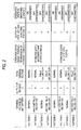
- patterns 1 to 4 shows the operation state of switching element when the main body of computer stays in the state other than the states (i) and (ii)
- patterns 5 to 8 shows the operation state of switching element when the main body of computer stays in the state (i) or (ii).
- the sleep state exists when the user does not use the personal computer over a predetermined period of time or longer and thus is often allowed to stand over an extended period of time.
- overdischarge it is similarly preferred that overdischarge be preferentially prevented.
- the present embodiment is arranged such that when any of the unit batteries 2 shows a terminal voltage of less than 2.5 V, the power supply is forced to be turned off.
- the unit batteries When all the unit batteries show a terminal voltage of not lower than 2.5 V and the output of the AND gate is on a low level, if the total terminal voltage falls below 13.2 V, the NOR gate 13 outputs a low level signal which then turns the switching element 4 off (pattern 3). Accordingly, the unit batteries are disconnected from the main body of personal computer, making it possible to prevent the decomposition of the electrolyte due to overdischarge while it is stood over an extended period of time. Hence the desired safety and performance of the battery can be maintained.
- the active state sometimes continues for a extended period of time when a large amount of data is stored.
- an arrangement can be made such that the fact that some of the unit batteries 2 are overdischarged is made known to the exterior by displaying on the display of the personal computer or sounding an alarm.
- the active state is broken and the system takes processing awaiting state from active state.
- it possible to prevent as much as possible the power supply from being forced to be turned off in the active state. It is thought that when the battery is charged thereafter, the terminal voltage of some of the unit batteries 2 is restored, eliminating troubles.
- the NOR gate 13 When the battery is discharged as abnormally as the total terminal voltage falls below 11.2 V, the NOR gate 13 outputs a low level signal regardless of the output of the AND gate 12 to cause the switching element 4 to be turned off (patterns 7, 8), eliminating the risk of electrolyte leakage.
- Fig. 3 illustrates a second embodiment of implication of the invention.
- the second embodiment is the same as the first embodiment except the structure of the load state judging unit. Accordingly, like numerals are used for like components in the first and second embodiments. The description of like components is omitted. The components different from those of the first embodiment will be described hereinafter.
- the value of load current supplied from the secondary battery device 1 into the main body of personal computer varies with the operation state of the main body of personal computer. In some detail, when the power supply is turned off, the load current is not greater than several milliamperes (about 3 mA) . When the main body of personal computer stays in the idle state, the load current is scores of milliamperes (about 75 mA) . While only OS is being started, the load current is about 1 A on the average. While an application program is being started, the load current is about 1.5 A at maximum.
- a current detecting circuit 14 is provided between the positive electrode of the unit batteries 2 and the power supply terminal 5 instead of the signal terminal 8.
- the current detecting circuit 14 detects the load current flowing through the power supply line during discharge to the main body of personal computer.
- a predetermined reference value e.g. 70 mA
- a low level signal is given to the total voltage detecting portion 10 and the AND gate 12.
- a high level signal is given to the total voltage detecting portion 10 and the AND gate 12.
- the operation state of the main body of personal computer can be judged by the secondary battery device alone without using any arrangement such as reception of a signal indicating the operation state from the main body of personal computer.
Landscapes
- Physics & Mathematics (AREA)
- General Physics & Mathematics (AREA)
- Engineering & Computer Science (AREA)
- Power Engineering (AREA)
- Manufacturing & Machinery (AREA)
- Chemical & Material Sciences (AREA)
- Chemical Kinetics & Catalysis (AREA)
- Electrochemistry (AREA)
- General Chemical & Material Sciences (AREA)
- Charge And Discharge Circuits For Batteries Or The Like (AREA)
- Secondary Cells (AREA)
Abstract
A secondary battery device is disclosed comprising:

Description
The present invention relates to a secondary battery
device comprising an overdischarge protective unit and a method
of protecting an overdischarge of the secondary battery.
A secondary battery device comprises, e.g., a plurality
of unit batteries connected in series. In such a secondary
battery device, some of the unit batteries can be overcharged
or overdischarged due to variation of the capacity or internal
impedance of the unit batteries. For example, when a lithium
ion battery as a unit battery is overcharged beyond a tolerance
voltage, the decomposition reaction of an organic electrolyte
proceeds. On the contrary, when the lithium ion battery is
overdischarged, it shows an increase of internal resistance
or the like, causing the deterioration of performance or safety
thereof.
Thus, a battery device normally comprises a protective
circuit incorporated therein. The group of unit batteries is
electrically connected to an external circuit, such as load
and charger, through the protective circuit. The protective
circuit individually detects the terminal voltage of each of
the unit batteries. When one of the unit batteries shows a
terminal voltage of higher than a predetermined reference
voltage, the protective circuit causes an FET element or the
like to disconnect the battery device from the external circuit
so that charge or discharge is forced to suspend. Therefore,
the overcharge and overdischarge can be prevented, thereby
protecting the unit batteries.
A potable personal computer or the like is subject to
defectives, such as troubles in hard disk, when the power supply
is forced to be turned off while CPU is in a predetermined
operation state, such as reading of data. Such a forced
suspension of discharge should be avoided as much as possible.
It is inconvenient also for cellular phone that the power supply
is forced to be turned off during communication.
In the conventional secondary battery device, when the
terminal voltages of the unit batteries show a great variation,
the protective circuit causes the suspension of discharge to
an apparatus such as main body of personal computer to prevent
one of the unit batteries from being overdischarged, even if
the total battery voltage of the secondary battery device falls
within a normal range which allows the supply of electric power
high enough to operate the apparatus. As a result, it is much
likely that the power supply can be forced to be turned off
even when CPU of personal computer is in a predetermined
operation state or cellular phone is communicating. Of course,
it is necessary that the unit batteries be protected against
overdischarge or the like. However, there are many cases where
the continuation of predetermined operation state of load should
be given priority.
An object of the invention is to provide a secondary
battery device and a method of protecting an overdischarge of
the secondary battery, which is subject as little as possible
to defectives, such as disconnection of power supply in a
predetermined operation state of load.
In order to accomplish the object above, the following
means are adopted. The secondary battery device according to
a first aspect of the invention comprises a secondary battery,
a load state judging unit, and an overdischarge protective unit
connected to the secondary battery. The secondary battery
supplies electric power into a load circuit. The load state
judging unit judges the operation state of the load circuit.
The overdischarge protective unit detects the discharged state
of the secondary battery, and breaks the discharge from the
secondary battery when the secondary battery reaches a
predetermined discharged state. When the load state judging
unit judges the load circuit stays in a predetermined operation
state requiring the protection of power supply, the supply of
electric power into the load circuit is allowed to continue
without breaking the discharge from the secondary battery.
The "a predetermined operation state of the load circuit
requiring the protection of power supply" as used herein may
be set to stay in any of the following states (1), (2). The
predetermined operation state of the load circuit may be
arbitrarily set by the user or may be previously fixed to the
definite conditions by the manufacturer.
In accordance with the present invention, the
overdischarge protective unit allows the supply of electric
power into the load circuit to continue without breaking the
discharge from the secondary battery when the load state judging
unit judges that the load circuit stays in the predetermined
operation state requiring the protection of power supply.
Accordingly, the occurrence of defectives such as sudden
disconnection of power supply can be prevented as much as
possible when the load circuit stays in the predetermined
operation state requiring the protection of power supply, such
as state where the hard disk of personal computer is driven
or communicating state of cellular phone.
The risk of overdischarging to an extent such that the
terminal voltage of the secondary battery falls below a
predetermined reference voltage can be eliminated by providing
the secondary battery device with an overdischarge preventive
function on the load circuit side thereof. The secondary
battery device may be overdischarged when the load circuit stays
in a predetermined operation state. However, it is thought
that the load circuit stays in a predetermined operation state
requiring the protection of power supply for a short period
of time. Accordingly, the operation of the load circuit is
normally terminated as early as possible by the use of a mechanism
which informs the exterior of the fact that the secondary battery
is overdischarged. For example, the mechanism informs to the
exterior by means of displaying on the display of the personal
computer or sounding an alarm. By doing so, the secondary
battery device cannot reach an abnormal state developed by the
continuation of overdischarge and thus can be recovered to its
normal terminal voltage after being charged.
The secondary battery may be a plurality of unit batteries
connected in series. The unit battery includes not only a single
battery cell but also a plurality of battery cells connected
in parallel.
A secondary battery device according to a second aspect
of the invention comprises a secondary battery, a load state
judging unit, a total voltage detecting unit, and an
overdischarge protective unit. The secondary battery
comprises a series combination of a plurality of unit batteries.
The load state judging unit judges the operation state of the
load circuit. The total voltage detecting unit detects the
total terminal voltage of the plurality of unit batteries. The
overdischarge protective unit is connected to the plurality
of unit batteries. The overdischarge protective unit detects
the discharged state of each of the unit batteries based on
their terminal voltage, and breaks the discharge from said
secondary battery when any of the unit batteries reaches a
predetermined overdischarge state. When the load state judging
unit judges that the load circuit stays in a predetermined
operation state requiring the protection of power supply, the
supply of electric power into the load circuit is allowed to
continue without breaking the discharge from the secondary
battery when the total terminal voltage is not lower than a
predetermined total reference voltage even if any of the
plurality of unit batteries shows a terminal voltage falling
below a predetermined unit reference voltage.
In this arrangement, when the load state judging unit
judges that the load circuit stays in a predetermined operation
state requiring the protection of power supply, the supply of
electric power into the load circuit is allowed to continue
when-the total terminal voltage is not lower than a predetermined
total reference voltage even if any of the plurality of unit
batteries shows a terminal voltage falling below a predetermined
unit reference voltage. Accordingly, even when the secondary
battery device is not provided with an overdischarge preventive
function on the load circuit side thereof, the risk of
overdischarging to an extent such that the total terminal voltage
of the secondary battery falls below a predetermined total
reference voltage can be eliminated by the secondary battery
device alone.
In the above-mentioned secondary battery, it is
preferable that the load state judging unit judges the operation
state of the load circuit on the basis of a load current value
supplied into the load circuit.
In this arrangement, the operation state of the main body
of personal computer can be judged by the secondary battery
device alone without using any arrangement such as reception
of a signal indicating the operation state from the main body
of personal computer.
The first embodiment of implication of the invention will
be further described in connection with Figs. 1 and 2.
A secondary battery device 1 according to the present
embodiment is used. e.g., as a power supply for portable personal
computer. Fig. 1 shows the electrical configuration of the
secondary battery device 1. A battery cell 2 (2a to 2d)
corresponds to "unit battery" of the present invention
(hereinafter the battery cell 2 is referred as unit battery
2). A secondary battery 3 (nominal voltage: 14.8 V (= 3.7 x
4)) comprises four unit batteries 2 (2a to 2d) in series. The
secondary battery 3 is connected to a power supply terminal
5 on the positive side thereof through a switch element 4 such
as an FET. Further, the secondary battery 3 is connected to
a grounding terminal 6 on the negative side thereof. By turning
the switching element 4 on, electric power is supplied into
the main body of a personal computer (not shown) connected to
the power supply terminal 5 and the grounding terminal 6. On
the contrary, by turning the switching element 4 off, the
discharge to the main body of personal computer breaks to suspend
the supply of electric power into the main body of personal
computer. A controller 7 performs on-off control of the
switching element 4 on the basis of the terminal voltage of
the unit battery 2 as described later. the controller 7 and
the switching element 4 corresponds to the "overdischarge
protective unit" of the present invention.
A signal terminal 8 corresponds to the "load state judging
unit" of the present invention. The signal terminal 8 receives
a low level signal from a detection circuit (not shown) provided
in the main body of personal computer when the main body of
personal computer stays in any of the following states (i) and
(ii). When the main body of personal computer stays in neither
of the following states (i) and (ii), the signal terminal 8
receives a high level signal from the detection circuit. These
signals are given to a total voltage detecting portion 10 and
an AND gate 12 described later.
The above states (i) and (ii) correspond to the "operation
state requiring the protection of power supply" of the present
invention.
The internal configuration of the controller 7 will be
described hereinafter. The interior of the controller 7
comprised four voltage detecting portions 9a to 9d, a total
voltage detecting portion 10, an OR gate 11, an AND gate 12,
and an NOR gate 13. The voltage detection portions 9a to 9d
detect the terminal voltage of the respective unit batteries
2. The total voltage detecting portion 10 detects the total
terminal voltage of the unit batteries 2. The voltage detecting
portions 9a to 9d are provided for the respective unit batteries
2 to detect individually the terminal voltage thereof. When
the detected terminal voltage falls below a unit reference
voltage (e.g., 2.5 V), a high level signal is then given to
the AND gate 12. The total voltage detecting portion 10 is
connected to the positive electrode or negative electrode of
the both end unit batteries 2a and 2d of the unit batteries
to detect the total terminal voltage of the unit batteries 2
and compare it with a total reference voltage. When the detected
voltage is not lower than the total reference voltage, a low
level signal is outputted to the NOR gate 13. On the contrary,
when the detected voltage falls below the total reference voltage,
a high level signal is outputted to the NOR gate 13.
Two such total reference voltages are selectively
provided. When a low level signal is received from the signal
terminal 8 (when the main body of personal computer stays in
the foregoing state (i) or (ii)), a first total reference voltage
(e.g., 11.2 V) is set as the total reference voltage of the
total voltage detecting portion 10. On the contrary, when a
high level signal is received from the terminal signal 8 (when
the main body of personal computer stays in a state other than
the foregoing states (i) and (ii), e.g., sleep state described
later), a second total reference voltage (e.g., 13.2 V) is set
as the total reference voltage of the total voltage detecting
portion 10.
The first and second reference voltages may be the same
or different. However, the discharge current is smaller in
the state other than the states (i) and (ii) than in the state
(i) or (ii). Therefore, when the main body of computer stays
in the state other than the states (i) and (ii), the resulting
voltage drop is small, causing the suspension of discharge at
the detected voltage close to the open circuit voltage. On
the contrary, when the main body of computer stays in the state
(i) or (ii), the resulting voltage drop is great, causing the
suspension of discharge at a voltage considerably lower than
the open circuit voltage. Accordingly, when the first and
second total reference voltages are predetermined to the same
value, overdischarge occurs more deeply in the operation state
other than the states (i) and (ii) than in the states (i) or
(ii). In order to avoid this trouble, it is preferred in the
present embodiment that the first total reference voltage (e.g.,
11.2 V) in the operation state (i) or (ii) be predetermined
to be lower than the second total reference voltage (e.g., 13.2
V) in the operation state other than the states (i) and (ii).
By doing so, when the main body of personal computer stays in
the operation state other than the states (i) and (ii), the
overdischarge protective unit can be actuated earlier.
To the input terminal of the OR gate 11 are connected
the output of the voltage detecting portions 9a to 9d. When
any of the terminal voltage of the unit batteries 2 detected
by the voltage detecting portions 9a to 9d falls below 2.5 V
(unit reference voltage), a high level signal is then given
to the input of the AND gate 12. When both the output of the
OR gate 11 and the output of the signal terminal 8 are on a
high level, the AND gate 12 outputs a high level signal. In
other cases, the AND gate 12 outputs a low level signal. The
NOR gate 13 outputs a signal (low level signal) which indicates
the disconnection of the main body of personal computer from
the unit batteries 2, to the switching element 4 when the output
of the AND gate 12 is on a high level or a high level signal
which indicates that the detected voltage of the total voltage
detecting portion 10 falls below 11.3V (the first total reference
voltage) or 13.2 V(the second total reference voltage) is
inputted to the NOR gate 13 from the total voltage detecting
portion 10.
The operation of the present embodiment having the
foregoing constitution will be described hereinafter by
referring to the operation state table shown in Fig. 2.
A personal computer stays in the foregoing state of hard
disk driving or active state as well as in various operation
states such as state awaiting input signal during the starting
of application program. These states require different
electric current values to be supplied.
For example, when the processing awaiting state continues
for a predetermined period of time with the application program
being started, displaying on the display is extinguished and
the operating speed of CPU is lowered to proceed to a processing
awaiting state with low power consumption of personal computer,
i.e., so-called sleep state. Even in such a sleep state,
electric current of several milliamperes always flows from the
secondary battery 3 to the main body of personal computer. Thus,
the secondary battery 3 is gradually discharged. Therefore,
some of the unit batteries 2 show a terminal voltage of lower
than 2.5 V due to the variation of the capacity of the unit
batteries 2 of the secondary battery 3, etc.
In Fig. 2, patterns 1 to 4 shows the operation state of
switching element when the main body of computer stays in the
state other than the states (i) and (ii), patterns 5 to 8 shows
the operation state of switching element when the main body
of computer stays in the state (i) or (ii).
As shown in Fig. 2, in patterns 1 to 4, since the output
of the signal terminal 8 is always on a high level, when the
terminal voltage of some of the unit batteries 2 falls below
2.5 V and the OR gate 11 outputs a high level signal, the output
of the AND gate 12 is on a high level. Hence, the NOR gate
13 outputs the low level signal, causing the switching element
4 to be turned off (patterns 2, 4). In other words, regardless
of the total terminal voltage of all the unit batteries 2, the
unit batteries 2 are disconnected from the main body of personal
computer so that the power supply is forced to be turned off.
Thus, the unit batteries 2 are preferentially prevented from
being overdischarged, making it possible to prevent the
deterioration of performance or life of the secondary battery
3.
When the power supply is forced to be turned off in the
sleep state, data which has not been saved so far can be lost.
However, the sleep state exists when the user does not use the
personal computer over a predetermined period of time or longer
and thus is often allowed to stand over an extended period of
time. For such an operation state which can be allowed to stand
over an extended period of time, it is similarly preferred that
overdischarge be preferentially prevented. Accordingly, the
present embodiment is arranged such that when any of the unit
batteries 2 shows a terminal voltage of less than 2.5 V, the
power supply is forced to be turned off.
When all the unit batteries show a terminal voltage of
not lower than 2.5 V and the output of the AND gate is on a
low level, if the total terminal voltage falls below 13.2 V,
the NOR gate 13 outputs a low level signal which then turns
the switching element 4 off (pattern 3). Accordingly, the unit
batteries are disconnected from the main body of personal
computer, making it possible to prevent the decomposition of
the electrolyte due to overdischarge while it is stood over
an extended period of time. Hence the desired safety and
performance of the battery can be maintained.
On the other hand, when the main body of personal computer
reaches the foregoing active state upon the reception of input
signal inputted by key operation before reaching the foregoing
sleep state, a large load current flows from the secondary
battery 3 to the main body of personal computer. Then, some
of the unit batteries 2 may show a terminal voltage of less
than 2.5 V even for a short period of time due to the variation
of capacity of the unit batteries of the secondary battery 3.
Therefore, as shown in Fig. 2, in patterns 5 to 8, since
the signal from the signal terminal 8 is always on a low level,
even when some of the unit batteries 2 show a terminal voltage
of less than 2.5V and the OR gate 11 outputs a high level signal,
the output of AND gate 12 is on a low level. Accordingly, the
NOR gate 13 outputs a high level signal which then keeps the
switching element 4 on to cause the supply of electric power
to continue so far as the total terminal voltage of all the
unit batteries 2 does not falls below 11.2 V (pattern 6).
Although, some of the unit batteries 2 which show the terminal
voltage of less than 2.5 V are kept to be discharged during
this period, this active state is normally terminated in a short
period of time and then the processing awaiting state is again
reached. Thereafter, as in the foregoing sleep state, some
of the unit batteries 2 show a terminal voltage of less than
2.5 V, forcing the power supply to be turned off. Thus, by
preventing as much as possible the power supply from being forced
to be turned off in the active state, the occurrence of defectives
of the hard disk can be prevented.
The active state sometimes continues for a extended period
of time when a large amount of data is stored. In this case,
an arrangement can be made such that the fact that some of the
unit batteries 2 are overdischarged is made known to the exterior
by displaying on the display of the personal computer or sounding
an alarm. With such arrangement, the active state is broken
and the system takes processing awaiting state from active state.
Hence, it possible to prevent as much as possible the power
supply from being forced to be turned off in the active state.
It is thought that when the battery is charged thereafter, the
terminal voltage of some of the unit batteries 2 is restored,
eliminating troubles. When the battery is discharged as
abnormally as the total terminal voltage falls below 11.2 V,
the NOR gate 13 outputs a low level signal regardless of the
output of the AND gate 12 to cause the switching element 4 to
be turned off (patterns 7, 8), eliminating the risk of
electrolyte leakage.
Thus, while the hard disk is being driven, or while CPU
of the main body of personal computer stays in the active state,
even if some of the unit batteries 2 show a terminal voltage
of less than 2.5V, discharge to the main body of personal computer
is continued to prevent the power supply from being forced to
be turned off so far as the total terminal voltage of the secondary
battery 3 does not falls below 11.2 V. Accordingly, the
occurrence of defectives on hard disk or the like due to forced
disconnection of power supply can be prevented as much as
possible.
Fig. 3 illustrates a second embodiment of implication
of the invention. The second embodiment is the same as the first
embodiment except the structure of the load state judging unit.
Accordingly, like numerals are used for like components in the
first and second embodiments. The description of like
components is omitted. The components different from those
of the first embodiment will be described hereinafter.
The value of load current supplied from the secondary
battery device 1 into the main body of personal computer varies
with the operation state of the main body of personal computer.
In some detail, when the power supply is turned off, the load
current is not greater than several milliamperes (about 3 mA) .
When the main body of personal computer stays in the idle state,
the load current is scores of milliamperes (about 75 mA) . While
only OS is being started, the load current is about 1 A on the
average. While an application program is being started, the
load current is about 1.5 A at maximum. In the present embodiment,
a current detecting circuit 14 is provided between the positive
electrode of the unit batteries 2 and the power supply terminal
5 instead of the signal terminal 8. The current detecting
circuit 14 detects the load current flowing through the power
supply line during discharge to the main body of personal
computer. When the load current thus detected exceeds a
predetermined reference value (e.g., 70 mA), a low level signal
is given to the total voltage detecting portion 10 and the AND
gate 12. On the contrary, when the load current thus detected
falls below the predetermined reference value, a high level
signal is given to the total voltage detecting portion 10 and
the AND gate 12. The operation of the controller 7 on the basis
of the change of signal level is the same as the operation based
on the change of signal level of the signal terminal 8 in the
first embodiment.
In this arrangement, the operation state of the main body
of personal computer can be judged by the secondary battery
device alone without using any arrangement such as reception
of a signal indicating the operation state from the main body
of personal computer.
The invention is not limited to the foregoing embodiments.
The following embodiments are included in the technical scope
of the invention. Other various changes and modifications can
be made therein without departing from the spirit and scope
thereof.
Claims (8)
- A secondary battery device comprising:a secondary battery for supplying electric power into a load circuit;a load state judging unit for judging an operation state of said load circuit; andan overdischarge protective unit connected to said secondary battery for detecting a discharged state of said secondary battery and breaking the discharge from said secondary battery when said secondary battery reaches a predetermined overdischarged state, said over discharge protective unit allows the supply of electric power into said load circuit to continue without breaking the discharge from said secondary battery when said load state judging unit judges that said load circuit stays in a predetermined operation state requiring a protection of power supply.
- A secondary battery device comprising:a secondary battery comprising a series combination of a plurality of unit batteries for supplying electric power into a load circuit;a load state judging unit for judging an operation state of said load circuit;a total voltage detecting unit for detecting a total terminal voltage of said plurality of unit batteries; andan overdischarge protective unit connected to said plurality of unit batteries for detecting a discharged state of each of said unit batteries and breaking the discharge from said secondary battery when any of said unit batteries reaches a predetermined overdischarge state, said overdischarge protective unit allowing the supply of electric power into said load circuit to continue without breaking the discharge from said secondary battery if the total terminal voltage is not lower than a predetermined total reference voltage, when said load state judging unit judges that said load circuit stays in a predetermined operation state requiring a protection of power supply.
- The secondary battery device according to Claim 1, wherein said load state judging unit judges the operation state of said load circuit on the basis of a load current value supplied into said load circuit.
- The secondary battery device according to Claim 2, wherein said load state judging unit judges the operation state of said load circuit on the basis of a load current value supplied into said load circuit.
- Amethod of protecting an overdischarge of a secondary battery, said method comprising:wherein the supply of electric power into said load circuit continues without breaking the discharge from said secondary battery when said load circuit is judged that it stays in a predetermined operation state requiring a protection of power supply.supplying electric power into a load circuit;judging an operation state of said load circuit; anddetecting a discharged state of said secondary battery and breaking the discharge from said secondary battery when said secondary battery reaches a predetermined overdischarged state,
- The method of protecting an overdischarge of a secondary battery device according to claim 5, further comprising:wherein the supply of electric power into said load circuit continues without breaking the discharge from said secondary battery if the total terminal voltage is not lower than a predetermined total reference voltage, when said load circuit is judged that it stays in the predetermined operation state requiring the protection of power supply.detecting a total terminal voltage of a plurality of unit batteries of a secondary battery; anddetecting a discharged state of each of said unit batteries and breaking the discharge from said secondary battery when any of said unit batteries reaches a predetermined overdischarge state,
- The method of protecting an overdischarge of a secondary battery device according to claim 5, wherein the operation state of said load circuit is judged on the basis of a load current value supplied into said load circuit.
- The method of protecting an overdischarge of a secondary battery device according to claim 6, wherein the operation state of said load circuit is judged on the basis of a load current value supplied into said load circuit.
Applications Claiming Priority (4)
| Application Number | Priority Date | Filing Date | Title |
|---|---|---|---|
| JP2001015233 | 2001-01-24 | ||
| JP2001015233 | 2001-01-24 | ||
| JP2001378936 | 2001-12-12 | ||
| JP2001378936A JP3883183B2 (en) | 2001-01-24 | 2001-12-12 | Secondary battery device |
Publications (1)
| Publication Number | Publication Date |
|---|---|
| EP1227533A2 true EP1227533A2 (en) | 2002-07-31 |
Family
ID=26608172
Family Applications (1)
| Application Number | Title | Priority Date | Filing Date |
|---|---|---|---|
| EP02001697A Withdrawn EP1227533A2 (en) | 2001-01-24 | 2002-01-24 | Secondary battery device and method of protecting an overdischarge of the same |
Country Status (5)
| Country | Link |
|---|---|
| US (1) | US6518728B2 (en) |
| EP (1) | EP1227533A2 (en) |
| JP (1) | JP3883183B2 (en) |
| KR (1) | KR20020062819A (en) |
| CN (1) | CN1372346A (en) |
Cited By (2)
| Publication number | Priority date | Publication date | Assignee | Title |
|---|---|---|---|---|
| CN103023115A (en) * | 2012-12-20 | 2013-04-03 | 浙江万马新能源有限公司 | Alternating current charging pile |
| CN110007194A (en) * | 2019-04-22 | 2019-07-12 | 国网河北省电力有限公司石家庄市鹿泉区供电分公司 | A charging and discharging pile leakage fault location acquisition system |
Families Citing this family (6)
| Publication number | Priority date | Publication date | Assignee | Title |
|---|---|---|---|---|
| ITMI20061438A1 (en) * | 2006-07-24 | 2008-01-25 | Campagnolo Srl | METHOD AND RECHARGING SYSTEM OF A BATTERY POWER UNIT |
| JP5262034B2 (en) * | 2007-09-14 | 2013-08-14 | 株式会社リコー | Charge / discharge protection circuit, battery pack incorporating the charge / discharge protection circuit, and electronic device using the battery pack |
| US7800247B2 (en) * | 2008-05-30 | 2010-09-21 | Chun-Chieh Chang | Storage system that maximizes the utilization of renewable energy |
| US8502503B2 (en) * | 2008-12-18 | 2013-08-06 | O2Micro Inc. | Circuits and methods for protection of battery modules |
| WO2012102352A1 (en) * | 2011-01-28 | 2012-08-02 | 住友重機械工業株式会社 | Shovel |
| US20120280572A1 (en) * | 2011-05-05 | 2012-11-08 | O2Micro, Inc. | Battery systems and controllers |
Family Cites Families (2)
| Publication number | Priority date | Publication date | Assignee | Title |
|---|---|---|---|---|
| JP3597617B2 (en) * | 1995-12-27 | 2004-12-08 | 株式会社日立超エル・エス・アイ・システムズ | Secondary battery protection circuit |
| US6340880B1 (en) * | 1999-11-11 | 2002-01-22 | Mitsumi Electric Co., Ltd. | Method of protecting a chargeable electric cell |
-
2001
- 2001-12-12 JP JP2001378936A patent/JP3883183B2/en not_active Expired - Fee Related
-
2002
- 2002-01-22 KR KR1020020003515A patent/KR20020062819A/en not_active Withdrawn
- 2002-01-23 US US10/052,596 patent/US6518728B2/en not_active Expired - Lifetime
- 2002-01-24 EP EP02001697A patent/EP1227533A2/en not_active Withdrawn
- 2002-01-24 CN CN02102395A patent/CN1372346A/en active Pending
Cited By (2)
| Publication number | Priority date | Publication date | Assignee | Title |
|---|---|---|---|---|
| CN103023115A (en) * | 2012-12-20 | 2013-04-03 | 浙江万马新能源有限公司 | Alternating current charging pile |
| CN110007194A (en) * | 2019-04-22 | 2019-07-12 | 国网河北省电力有限公司石家庄市鹿泉区供电分公司 | A charging and discharging pile leakage fault location acquisition system |
Also Published As
| Publication number | Publication date |
|---|---|
| KR20020062819A (en) | 2002-07-31 |
| US6518728B2 (en) | 2003-02-11 |
| JP2002300732A (en) | 2002-10-11 |
| US20020158608A1 (en) | 2002-10-31 |
| JP3883183B2 (en) | 2007-02-21 |
| CN1372346A (en) | 2002-10-02 |
Similar Documents
| Publication | Publication Date | Title |
|---|---|---|
| JP3618472B2 (en) | Battery unit and device using battery unit | |
| KR100193736B1 (en) | Battery pack with battery protection | |
| US6025699A (en) | Self discharge of batteries at high temperatures | |
| JP3219524B2 (en) | Overdischarge protection circuit for secondary battery | |
| US6518728B2 (en) | Secondary battery device and method of protecting an overdischarge of the same | |
| JPH11225444A (en) | Battery pack | |
| JPH0956056A (en) | Secondary-battery power unit, protective circuit, and method for protecting secondary battery from being abnormally charged | |
| JP2002078222A (en) | Lithium ion secondary battery charging circuit and battery pack | |
| JPH10290530A (en) | Secondary battery protection circuit | |
| KR100553525B1 (en) | Battery protection circuit | |
| KR20070105219A (en) | Battery pack protection circuit | |
| JP3331200B2 (en) | Module battery protection device and power storage device | |
| US7449864B2 (en) | Apparatus and method for controlling battery discharge between internal battery and external battery | |
| JP3894377B2 (en) | BATTERY PACK AND BATTERY PACK CONTROL METHOD | |
| JPH1198702A (en) | Battery abnormality detection device and battery pack | |
| JP2939689B2 (en) | Monitoring and control equipment for organic electrolyte secondary batteries and assembled batteries | |
| JPH10150721A (en) | Protective circuit for secondary battery | |
| JPH04344129A (en) | Electronic apparatus | |
| CN109524946B (en) | BMS battery protection system | |
| EP1253696A1 (en) | A method of charging a battery | |
| KR200280002Y1 (en) | Lithium-ion battery protective circuit | |
| CN114156956B (en) | Cell protection circuits, batteries and terminal equipment | |
| US20040207363A1 (en) | Method of charging a battery | |
| JP2003164070A (en) | Charger | |
| KR20070109084A (en) | Battery pack |
Legal Events
| Date | Code | Title | Description |
|---|---|---|---|
| PUAI | Public reference made under article 153(3) epc to a published international application that has entered the european phase |
Free format text: ORIGINAL CODE: 0009012 |
|
| AK | Designated contracting states |
Kind code of ref document: A2 Designated state(s): AT BE CH CY DE DK ES FI FR GB GR IE IT LI LU MC NL PT SE TR |
|
| AX | Request for extension of the european patent |
Free format text: AL;LT;LV;MK;RO;SI |
|
| STAA | Information on the status of an ep patent application or granted ep patent |
Free format text: STATUS: THE APPLICATION IS DEEMED TO BE WITHDRAWN |
|
| 18D | Application deemed to be withdrawn |
Effective date: 20040801 |