EP1227286A1 - Air conditioner - Google Patents
Air conditioner Download PDFInfo
- Publication number
- EP1227286A1 EP1227286A1 EP00969980A EP00969980A EP1227286A1 EP 1227286 A1 EP1227286 A1 EP 1227286A1 EP 00969980 A EP00969980 A EP 00969980A EP 00969980 A EP00969980 A EP 00969980A EP 1227286 A1 EP1227286 A1 EP 1227286A1
- Authority
- EP
- European Patent Office
- Prior art keywords
- heat exchanger
- indoor
- temperature
- air conditioner
- control means
- Prior art date
- Legal status (The legal status is an assumption and is not a legal conclusion. Google has not performed a legal analysis and makes no representation as to the accuracy of the status listed.)
- Granted
Links
- 238000010981 drying operation Methods 0.000 claims abstract description 28
- 230000007246 mechanism Effects 0.000 claims abstract description 22
- 230000008859 change Effects 0.000 claims description 2
- 239000003507 refrigerant Substances 0.000 abstract description 25
- 238000001816 cooling Methods 0.000 description 7
- 238000001704 evaporation Methods 0.000 description 7
- 230000008020 evaporation Effects 0.000 description 7
- 238000010438 heat treatment Methods 0.000 description 7
- 238000009833 condensation Methods 0.000 description 5
- 230000005494 condensation Effects 0.000 description 5
- 238000000034 method Methods 0.000 description 4
- 238000004378 air conditioning Methods 0.000 description 2
- 230000008901 benefit Effects 0.000 description 2
- 230000000694 effects Effects 0.000 description 2
- 238000012986 modification Methods 0.000 description 2
- 230000004048 modification Effects 0.000 description 2
- 240000008574 Capsicum frutescens Species 0.000 description 1
- 238000005452 bending Methods 0.000 description 1
- 230000015556 catabolic process Effects 0.000 description 1
- 238000006731 degradation reaction Methods 0.000 description 1
- 238000007791 dehumidification Methods 0.000 description 1
- 238000010586 diagram Methods 0.000 description 1
- 238000005259 measurement Methods 0.000 description 1
- 239000011295 pitch Substances 0.000 description 1
- 230000009467 reduction Effects 0.000 description 1
Images




Classifications
-
- F—MECHANICAL ENGINEERING; LIGHTING; HEATING; WEAPONS; BLASTING
- F25—REFRIGERATION OR COOLING; COMBINED HEATING AND REFRIGERATION SYSTEMS; HEAT PUMP SYSTEMS; MANUFACTURE OR STORAGE OF ICE; LIQUEFACTION SOLIDIFICATION OF GASES
- F25B—REFRIGERATION MACHINES, PLANTS OR SYSTEMS; COMBINED HEATING AND REFRIGERATION SYSTEMS; HEAT PUMP SYSTEMS
- F25B49/00—Arrangement or mounting of control or safety devices
- F25B49/02—Arrangement or mounting of control or safety devices for compression type machines, plants or systems
-
- F—MECHANICAL ENGINEERING; LIGHTING; HEATING; WEAPONS; BLASTING
- F24—HEATING; RANGES; VENTILATING
- F24F—AIR-CONDITIONING; AIR-HUMIDIFICATION; VENTILATION; USE OF AIR CURRENTS FOR SCREENING
- F24F3/00—Air-conditioning systems in which conditioned primary air is supplied from one or more central stations to distributing units in the rooms or spaces where it may receive secondary treatment; Apparatus specially designed for such systems
- F24F3/12—Air-conditioning systems in which conditioned primary air is supplied from one or more central stations to distributing units in the rooms or spaces where it may receive secondary treatment; Apparatus specially designed for such systems characterised by the treatment of the air otherwise than by heating and cooling
- F24F3/14—Air-conditioning systems in which conditioned primary air is supplied from one or more central stations to distributing units in the rooms or spaces where it may receive secondary treatment; Apparatus specially designed for such systems characterised by the treatment of the air otherwise than by heating and cooling by humidification; by dehumidification
- F24F3/153—Air-conditioning systems in which conditioned primary air is supplied from one or more central stations to distributing units in the rooms or spaces where it may receive secondary treatment; Apparatus specially designed for such systems characterised by the treatment of the air otherwise than by heating and cooling by humidification; by dehumidification with subsequent heating, i.e. with the air, given the required humidity in the central station, passing a heating element to achieve the required temperature
-
- F—MECHANICAL ENGINEERING; LIGHTING; HEATING; WEAPONS; BLASTING
- F24—HEATING; RANGES; VENTILATING
- F24F—AIR-CONDITIONING; AIR-HUMIDIFICATION; VENTILATION; USE OF AIR CURRENTS FOR SCREENING
- F24F1/00—Room units for air-conditioning, e.g. separate or self-contained units or units receiving primary air from a central station
- F24F1/0007—Indoor units, e.g. fan coil units
- F24F1/0083—Indoor units, e.g. fan coil units with dehumidification means
-
- F—MECHANICAL ENGINEERING; LIGHTING; HEATING; WEAPONS; BLASTING
- F24—HEATING; RANGES; VENTILATING
- F24F—AIR-CONDITIONING; AIR-HUMIDIFICATION; VENTILATION; USE OF AIR CURRENTS FOR SCREENING
- F24F1/00—Room units for air-conditioning, e.g. separate or self-contained units or units receiving primary air from a central station
- F24F1/0007—Indoor units, e.g. fan coil units
- F24F1/0043—Indoor units, e.g. fan coil units characterised by mounting arrangements
- F24F1/0057—Indoor units, e.g. fan coil units characterised by mounting arrangements mounted in or on a wall
-
- F—MECHANICAL ENGINEERING; LIGHTING; HEATING; WEAPONS; BLASTING
- F24—HEATING; RANGES; VENTILATING
- F24F—AIR-CONDITIONING; AIR-HUMIDIFICATION; VENTILATION; USE OF AIR CURRENTS FOR SCREENING
- F24F1/00—Room units for air-conditioning, e.g. separate or self-contained units or units receiving primary air from a central station
- F24F1/0007—Indoor units, e.g. fan coil units
- F24F1/0059—Indoor units, e.g. fan coil units characterised by heat exchangers
- F24F1/0063—Indoor units, e.g. fan coil units characterised by heat exchangers by the mounting or arrangement of the heat exchangers
-
- F—MECHANICAL ENGINEERING; LIGHTING; HEATING; WEAPONS; BLASTING
- F25—REFRIGERATION OR COOLING; COMBINED HEATING AND REFRIGERATION SYSTEMS; HEAT PUMP SYSTEMS; MANUFACTURE OR STORAGE OF ICE; LIQUEFACTION SOLIDIFICATION OF GASES
- F25B—REFRIGERATION MACHINES, PLANTS OR SYSTEMS; COMBINED HEATING AND REFRIGERATION SYSTEMS; HEAT PUMP SYSTEMS
- F25B13/00—Compression machines, plants or systems, with reversible cycle
-
- F—MECHANICAL ENGINEERING; LIGHTING; HEATING; WEAPONS; BLASTING
- F25—REFRIGERATION OR COOLING; COMBINED HEATING AND REFRIGERATION SYSTEMS; HEAT PUMP SYSTEMS; MANUFACTURE OR STORAGE OF ICE; LIQUEFACTION SOLIDIFICATION OF GASES
- F25B—REFRIGERATION MACHINES, PLANTS OR SYSTEMS; COMBINED HEATING AND REFRIGERATION SYSTEMS; HEAT PUMP SYSTEMS
- F25B39/00—Evaporators; Condensers
- F25B39/02—Evaporators
-
- F—MECHANICAL ENGINEERING; LIGHTING; HEATING; WEAPONS; BLASTING
- F25—REFRIGERATION OR COOLING; COMBINED HEATING AND REFRIGERATION SYSTEMS; HEAT PUMP SYSTEMS; MANUFACTURE OR STORAGE OF ICE; LIQUEFACTION SOLIDIFICATION OF GASES
- F25B—REFRIGERATION MACHINES, PLANTS OR SYSTEMS; COMBINED HEATING AND REFRIGERATION SYSTEMS; HEAT PUMP SYSTEMS
- F25B2313/00—Compression machines, plants or systems with reversible cycle not otherwise provided for
- F25B2313/023—Compression machines, plants or systems with reversible cycle not otherwise provided for using multiple indoor units
- F25B2313/0234—Compression machines, plants or systems with reversible cycle not otherwise provided for using multiple indoor units in series arrangements
-
- F—MECHANICAL ENGINEERING; LIGHTING; HEATING; WEAPONS; BLASTING
- F25—REFRIGERATION OR COOLING; COMBINED HEATING AND REFRIGERATION SYSTEMS; HEAT PUMP SYSTEMS; MANUFACTURE OR STORAGE OF ICE; LIQUEFACTION SOLIDIFICATION OF GASES
- F25B—REFRIGERATION MACHINES, PLANTS OR SYSTEMS; COMBINED HEATING AND REFRIGERATION SYSTEMS; HEAT PUMP SYSTEMS
- F25B2313/00—Compression machines, plants or systems with reversible cycle not otherwise provided for
- F25B2313/023—Compression machines, plants or systems with reversible cycle not otherwise provided for using multiple indoor units
- F25B2313/0234—Compression machines, plants or systems with reversible cycle not otherwise provided for using multiple indoor units in series arrangements
- F25B2313/02341—Compression machines, plants or systems with reversible cycle not otherwise provided for using multiple indoor units in series arrangements during cooling
-
- F—MECHANICAL ENGINEERING; LIGHTING; HEATING; WEAPONS; BLASTING
- F25—REFRIGERATION OR COOLING; COMBINED HEATING AND REFRIGERATION SYSTEMS; HEAT PUMP SYSTEMS; MANUFACTURE OR STORAGE OF ICE; LIQUEFACTION SOLIDIFICATION OF GASES
- F25B—REFRIGERATION MACHINES, PLANTS OR SYSTEMS; COMBINED HEATING AND REFRIGERATION SYSTEMS; HEAT PUMP SYSTEMS
- F25B2313/00—Compression machines, plants or systems with reversible cycle not otherwise provided for
- F25B2313/023—Compression machines, plants or systems with reversible cycle not otherwise provided for using multiple indoor units
- F25B2313/0234—Compression machines, plants or systems with reversible cycle not otherwise provided for using multiple indoor units in series arrangements
- F25B2313/02343—Compression machines, plants or systems with reversible cycle not otherwise provided for using multiple indoor units in series arrangements during dehumidification
-
- F—MECHANICAL ENGINEERING; LIGHTING; HEATING; WEAPONS; BLASTING
- F25—REFRIGERATION OR COOLING; COMBINED HEATING AND REFRIGERATION SYSTEMS; HEAT PUMP SYSTEMS; MANUFACTURE OR STORAGE OF ICE; LIQUEFACTION SOLIDIFICATION OF GASES
- F25B—REFRIGERATION MACHINES, PLANTS OR SYSTEMS; COMBINED HEATING AND REFRIGERATION SYSTEMS; HEAT PUMP SYSTEMS
- F25B2313/00—Compression machines, plants or systems with reversible cycle not otherwise provided for
- F25B2313/023—Compression machines, plants or systems with reversible cycle not otherwise provided for using multiple indoor units
- F25B2313/0234—Compression machines, plants or systems with reversible cycle not otherwise provided for using multiple indoor units in series arrangements
- F25B2313/02344—Compression machines, plants or systems with reversible cycle not otherwise provided for using multiple indoor units in series arrangements during heating
-
- F—MECHANICAL ENGINEERING; LIGHTING; HEATING; WEAPONS; BLASTING
- F25—REFRIGERATION OR COOLING; COMBINED HEATING AND REFRIGERATION SYSTEMS; HEAT PUMP SYSTEMS; MANUFACTURE OR STORAGE OF ICE; LIQUEFACTION SOLIDIFICATION OF GASES
- F25B—REFRIGERATION MACHINES, PLANTS OR SYSTEMS; COMBINED HEATING AND REFRIGERATION SYSTEMS; HEAT PUMP SYSTEMS
- F25B2313/00—Compression machines, plants or systems with reversible cycle not otherwise provided for
- F25B2313/025—Compression machines, plants or systems with reversible cycle not otherwise provided for using multiple outdoor units
- F25B2313/0254—Compression machines, plants or systems with reversible cycle not otherwise provided for using multiple outdoor units in series arrangements
-
- F—MECHANICAL ENGINEERING; LIGHTING; HEATING; WEAPONS; BLASTING
- F25—REFRIGERATION OR COOLING; COMBINED HEATING AND REFRIGERATION SYSTEMS; HEAT PUMP SYSTEMS; MANUFACTURE OR STORAGE OF ICE; LIQUEFACTION SOLIDIFICATION OF GASES
- F25B—REFRIGERATION MACHINES, PLANTS OR SYSTEMS; COMBINED HEATING AND REFRIGERATION SYSTEMS; HEAT PUMP SYSTEMS
- F25B2700/00—Sensing or detecting of parameters; Sensors therefor
- F25B2700/02—Humidity
-
- F—MECHANICAL ENGINEERING; LIGHTING; HEATING; WEAPONS; BLASTING
- F25—REFRIGERATION OR COOLING; COMBINED HEATING AND REFRIGERATION SYSTEMS; HEAT PUMP SYSTEMS; MANUFACTURE OR STORAGE OF ICE; LIQUEFACTION SOLIDIFICATION OF GASES
- F25B—REFRIGERATION MACHINES, PLANTS OR SYSTEMS; COMBINED HEATING AND REFRIGERATION SYSTEMS; HEAT PUMP SYSTEMS
- F25B2700/00—Sensing or detecting of parameters; Sensors therefor
- F25B2700/21—Temperatures
- F25B2700/2104—Temperatures of an indoor room or compartment
Definitions
- the present invention relates to an air conditioner capable of conducting a reheat drying operation.
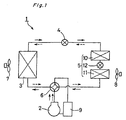
- This air conditioner 1 is a heat pump type air conditioner equipped with a compressor 2, outdoor heat exchanger 3, depressurizing mechanism 4 and indoor heat exchanger 5.
- the refrigerant circuit is constituted such that a refrigerant from the compressor 2 is circulated.
- the discharge side and the suction side of the compressor 2 are connected to primary ports of a four-path switching valve 6.
- a refrigerant circuit from one of secondary ports of the four-path switching valve 6 to the other secondary port of the four-path switching valve 6 via each of the outdoor heat exchanger 3 equipped with an outdoor fan 7, the depressurizing mechanism 4 and the indoor heat exchanger 5 equipped with an indoor fan 8 is constructed by refrigerant piping. It is noted that the refrigerant returns from the four-path switching valve 6 to the suction side of the compressor 2 via an accumulator 9. Furthermore, the indoor heat exchanger 5 consists of a first heat exchanger 10 and a second heat exchanger 11, which are connected in series, and a depressurizing mechanism 12 is disposed between these heat exchangers 10, 11.
- Types of air conditioning operations conducted by the aforementioned refrigerant circuit include a cooling operation, heating operation, reheat drying operation and so forth.
- the depressurizing mechanism 12 of the indoor heat exchanger 5 is made fully open, while the depressurizing mechanism 4 is adjusted to a prescribed opening and further the outdoor fan 7 and the indoor fan 8 are driven at a prescribed rotating speed.
- a refrigerant discharged from the compressor 2 is circulated as shown with unbroken line arrows so that the outdoor heat exchanger 3 is allowed to function as a condenser and that the indoor heat exchanger 5 is allowed to function as an evaporator in order to cool indoor air.
- a refrigerant discharged from the compressor 2 is circulated as shown with broken line arrows so that the indoor heat exchanger 5 is allowed to function as a condenser and that the outdoor heat exchanger 3 is allowed to function as an evaporator in order to heat indoor air.
- the depressurizing mechanism 12 of the indoor heat exchanger 5 is adjusted to a prescribed opening, while the depressurizing mechanism 4 is made fully open. Furthermore, the indoor fan 8 is driven at a prescribed rotating speed, while the outdoor fan 7 is stopped. Then, a refrigerant discharged from the compressor 2 is circulated by a cooling cycle as shown with unbroken line arrows so that the first heat exchanger 10 of the indoor heat exchanger 5 is allowed to function as a condenser, while the second heat exchanger 11 is allowed to function as an evaporator.
- a reheat drying operation is conducted wherein indoor air is cooled and dehumidified in the second heat exchanger 11 functioning as an evaporator, then reheated in the first heat exchanger 10 functioning as a condenser and returned indoors.
- an object of the present invention is to provide an air conditioner capable of reliably conducting a reheat drying operation by controlling the temperature of an evaporator to increase the dehumidifying amount even when the interior of a room is slightly heated while dehumidified.
- the present invention provides an air conditioner having an indoor heat exchanger 5 consisting of a first heat exchanger 10 and a second heat exchanger 11, which are connected in series, and a depressurizing mechanism 12 disposed between these heat exchangers 10, 11 and capable of conducting a reheat drying operation where the first heat exchanger 10 is allowed to function as a condenser, while the second heat exchanger 11 is allowed to function as an evaporator so that indoor air is cooled and dehumidified, then reheated and returned indoors, wherein there is provided a control means 13 for controlling temperature of the second heat exchanger 11 functioning as an evaporator during the reheat drying operation.
- the indoor equipment is equipped with a control means 13 for controlling the temperature of the second heat exchanger 11 functioning as an evaporator. Consequently, when the interior of a room is slightly heated while a reheat drying operation is conducted, the control means 13 can be used to lower the temperature of the second heat exchanger 11 or suppress its temperature rise even if the condensation temperature of the first heat exchanger 10 functioning as a condenser is raised. Therefore, a reheat drying operation can be reliably conducted without reducing the dehumidifying amount. As a result, indoor environment required by a user can be achieved, and hence comfort is improved. It is noted that, when the temperature of the second heat exchanger 11 is controlled as described above, there is an advantage that a reliable dehumidifying effect can be obtained during a usual reheat drying operation.
- an indoor temperature sensor 27 and a humidity sensor 28 are provided to obtain dew-point temperature obtained from temperature and humidity measured by these sensors 27, 28, while temperature of the second heat exchanger 11 is controlled on the basis of the dew-point temperature.
- this air conditioner is equipped with the indoor temperature sensor 27 and the humidity sensor 28, indoor temperature and humidity are measured, and the temperature of the second heat exchanger 11 is controlled on the basis of the dew-point temperature obtained from the measurement results by using the control means 13. As a result, precise dehumidifying control can be performed. Consequently, a reheat drying operation according to indoor environment required by the user can be conducted further reliably.
- control means 13 includes an air volume control means for controlling an air volume to the second heat exchanger 11.
- the temperature of the second heat exchanger 11 can be controlled by reducing a passing air volume by using the air volume control means.
- the dehumidifying amount can be reliably increased in a simple constitution.
- control means 13 includes a pressure control means which is constituted to be able to change opening of the depressurizing mechanism 12.
- the temperature of the second heat exchanger 11 can be controlled by controlling the depressurizing amount to the second heat exchanger 11 by using the pressure control means.
- the dehumidifying amount can be reliably increased in a simple constitution.
- a refrigerant circuit of an air conditioner basically has the same constitution as that of the refrigerant circuit of a common air conditioner 1 shown in Fig. 1, but has an improved control. That is, as shown in Fig. 1, the air conditioner 1 is a heat pump type air conditioner equipped with a compressor 2, outdoor heat exchanger 3, depressurizing mechanism 4 and indoor heat exchanger 5. Its refrigerant circuit is constituted such that a refrigerant from the compressor 2 is circulated. The discharge side and the suction side of the compressor 2 are connected to primary ports of a four-path switching valve 6.
- the refrigerant circuit from one of secondary ports of the four-path switching valve 6 to the other secondary port of the four-path switching valve 6 via each of the outdoor heat exchanger 3 equipped with an outdoor fan 7, the depressurizing mechanism 4 and the indoor heat exchanger 5 equipped with an indoor fan 8 is constructed by refrigerant piping. It is noted that the refrigerant returns from the four-path switching valve 6 to the suction side of the compressor 2 via an accumulator 9. Furthermore, the indoor heat exchanger 5 consists of a first heat exchanger 10 and a second heat exchanger 11, which are connected in series, and a depressurizing mechanism 12 is disposed between these heat exchangers 10, 11.
- Types of air conditioning operations conducted by the aforementioned refrigerant circuit include a cooling operation, heating operation, reheat drying operation and so forth.
- the depressurizing mechanism 12 of the indoor heat exchanger 5 is made fully open, while the depressurizing mechanism 4 is adjusted to a prescribed opening and further the outdoor fan 7 and the indoor fan 8 are driven at a prescribed rotating speed.
- a refrigerant discharged from the compressor 2 is circulated as shown with unbroken line arrows so that the outdoor heat exchanger 3 is allowed to function as a condenser and that the indoor heat exchanger 5 is allowed to function as an evaporator in order to cool indoor air.
- a refrigerant discharged from the compressor 2 is circulated as shown with broken line arrows so that the indoor heat exchanger 5 is allowed to function as a condenser and that the outdoor heat exchanger 3 is allowed to function as an evaporator in order to heat indoor air.
- the depressurizing mechanism 12 of the indoor heat exchanger 5 is adjusted to a prescribed opening, while the depressurizing mechanism 4 is made fully open. Furthermore, the indoor fan 8 is driven at a prescribed rotating speed, while the outdoor fan 7 is stopped. Then, a refrigerant discharged from the compressor 2 is circulated as shown with unbroken line arrows so that the first heat exchanger 10 of the indoor heat exchanger 5 is allowed to function as a condenser, while the second heat exchanger 11 is allowed to function as an evaporator.
- a reheat drying operation is conducted wherein indoor air is cooled and dehumidified in the second heat exchanger 11 functioning as an evaporator, then reheated in the first heat exchanger 10 functioning as a condenser and returned indoors.
- the outdoor heat exchanger 3 can also function as a condenser, outside air surrounding the outdoor heat exchanger 3 is not flowed therethrough by stopping the outdoor fan 7 as described above so that heat exchange is not performed in the outdoor heat exchanger 3 where possible.
- a controller 13 shown in Fig. 4 serves as a control means and controls the temperature of the second heat exchanger 11 functioning as an evaporator.
- Fig. 2 is a vertical cross sectional view showing indoor equipment of the air conditioner according to an embodiment.
- a grid-like top suction port 17 is formed over almost the whole surface of a top panel 16, and a grid-like front suction port 19 is formed over almost the whole surface of a front panel 18.
- the indoor heat exchanger 5 disposed in the casing 15 is divided into a rear side heat exchanger 10 (first heat exchanger) and a front side heat exchanger 11 (second heat exchanger) and is constituted by combining these in an inversed V shape.
- a crossflow fan 8 is disposed as an indoor fan inside the inversed V shaped indoor heat exchanger 5.
- a scroll unit 20 is formed behind this crossflow fan 8, and smoothly connected to a blowoff port 21 opening in a front side lower portion of the casing 15 of the indoor equipment.
- air conditioner 1 air cooled and dehumidified in the front side heat exchanger 10 and air heated in the rear side heat exchanger 11 are mixed in the equipment and blown off from the blowoff port 21 so that a reheat drying operation can be conducted.
- the indoor equipment of the air conditioner 1 is equipped with an air volume control means cooperating with the controller 13 to control an air volume supplied from the front suction port 19.
- the air volume control means is constituted by a shutter 22 capable of opening and closing the front suction port 19, a gear 23 with a motor for moving the shutter 22 along the inside of the front panel 18 and a reel 25 for reeling up the shutter 22.
- a rod-like reel 25 is disposed in an upper portion of the casing on the front panel 18 side so that its longitudinal direction should be substantially in parallel to the longitudinal direction of the casing 15.
- An upper end portion of the generally rectangular shutter 22 is attached to the reel 25 so that the shutter 22 is reeled up to the reel 25.
- a gear 23 having a rotating shaft 24 of a motor in its center is disposed at a position on the lower side of the reel 25, and the shutter 22 is disposed between the gear 23 and the front panel 18.
- projections and depressions having the same pitches as those of the gear 23 are formed on the inside surface of the shutter 22, that is a surface in a direction facing the gear 23.
- Fig. 4 is a perspective view showing the indoor equipment of the air conditioner 1.
- slits 29 are provided in a lower portion of the side surface of the indoor equipment main body 14.
- a temperature sensor 27 for measuring indoor temperature and a humidity sensor 28 for measuring indoor humidity are disposed in the rear of these slits.
- These sensors 27, 28 are provided so that the dew-point temperature is obtained from the indoor temperature and humidity in order to judge from this dew-point temperature whether temperature of the front side heat exchanger 11 should be controlled by using the air volume control means or not.
- these sensors 27, 28 are disposed in the indoor equipment, precise dew-point temperature can be obtained since indoor air comes in and out from the slits 29 provided in front of the sensors 27, 28. Therefore, indoor humidity and temperature can be precisely measured.
- Fig. 5 is a flow chart for explaining control operations using the air volume control means.
- step S1 whether temperature of the front side heat exchanger 11 functioning as an evaporator is lower than the dew-point temperature obtained from indoor temperature and humidity measured by the sensors 27, 28 is judged. In this case, when the temperature of the front side heat exchanger 11 is equal or higher, it means that dehumidifying ability may be insufficient. Therefore, the operation proceeds to step S2, where air volume distribution control using the shutter 22 used as an air volume control means is started and opening of the front suction port 19 is narrowed. Subsequently, the operation proceeds to step S3, where this state is maintained until the operation state is stabilized with the above opening (for about 10 minutes).
- step S1 when the dew-point temperature is higher, it means that dehumidifying ability is sufficient. Therefore, air volume distribution control using the shutter 22 is not performed, and the current state is maintained (step S4). Then, after a certain time elapses, the operation returns to step S1 again.
- a usual reheat drying operation is started so that the ratio of air volumes passing to the heat exchangers 10, 11 is basically constant.
- the reason why the air volume is not controlled from the beginning is to prevent degradation of the whole operation ability due to initial reduction of the air volume to the front side heat exchanger 11.
- opening of the front suction port 19 is adjusted to be automatically narrowed by the shutter 22 so that the suction air volume is reduced.
- opening of the front suction port 19 can be adjusted by the shutter 22 continuously, and the air volume distribution control is performed continuously until a reheat drying operation is executed while the interior of a room is slightly heated. Furthermore, even when the above operation is executed, the above judgment and control are performed every certain time so that this state is maintained at all times. Thus, even when condensation temperature of the rear side heat exchanger 10 functioning as a condenser is raised to heat the interior of a room slightly, temperature of the front side heat exchanger 11 functioning as an evaporator is lowered or its temperature rise can be suppressed by the air volume control means.
- a reheat drying operation can be conducted reliably without reducing the dehumidifying amount.
- indoor environment desired by a user can be achieved, and hence comfort is improved. It is noted that, when temperature of the front side heat exchanger 11 is controlled as described above, there is an advantage that a reliable dehumidifying effect can be obtained during a usual reheat drying operation.
- the present invention is not limited to the above embodiment, but various modifications can be implemented within a scope of the present invention.
- this is judged by comparing the temperature of the front side heat exchanger 11 used as an evaporator and the dew-point temperature.
- this may be judged by comparing the temperature of the front side heat exchanger 11 and the evaporation temperature required to make indoor humidity 50% or lower.
- the evaporation temperature required in this case can be obtained by using a sensor or the like, but a particular temperature may be preset in advance in consideration to an actual use state or the like.
- the air volume supplied from the front suction port 19 is controlled by using the shutter 22 as the air volume control means.
- the suction air volume can also be controlled by providing a front lid 30 which can cover the front suction port 19 from outside. That is, the front lid 30 has a shape obtained by slightly bending a generally rectangular plate in the vertical direction and is disposed so that its recessed portion faces inside, while its lower end portion is attached rotatably to the casing 15 at the lower portion of the front suction port 19.
- a rotating shaft 32 of a motor is provided at the center of an attaching portion 31, to which the front lid 30 is attached. By driving the motor, the front lid 30 rotates inward and outward by using the rotating shaft 32 of the attaching portion 31 as a center.
- the suction air volume can be controlled by adjusting opening of the front suction port 19 by the rotation of the front lid 30.
- temperature of the front side heat exchanger 11 is lowered to increase the dehumidifying amount by controlling the air volume passing through the front side heat exchanger 11 functioning as an evaporator, that is, reducing the suction air volume from the front suction port 19.
- the evaporation temperature of the front side heat exchanger 11 can also be lowered to increase the dehumidifying amount by controlling a pressure of the refrigerant, which flows into the front side heat exchanger 11.
- evaporation temperature in the front side heat exchanger 11 can be reduced to increase the dehumidifying amount by utilizing a depressurizing mechanism 12 provided on the entrance side of a refrigerant passage of the front side heat exchanger 11 as a pressure control means to narrow the opening of the depressurizing mechanism 12 and thereby increase the depressurizing amount.
- a depressurizing mechanism 12 provided on the entrance side of a refrigerant passage of the front side heat exchanger 11 as a pressure control means to narrow the opening of the depressurizing mechanism 12 and thereby increase the depressurizing amount.
- the indoor temperature sensor and the humidity sensor are disposed in the indoor equipment main body 14, but these may be disposed anywhere as long as indoor temperature and humidity can be measured.
Landscapes
- Engineering & Computer Science (AREA)
- Mechanical Engineering (AREA)
- General Engineering & Computer Science (AREA)
- Chemical & Material Sciences (AREA)
- Combustion & Propulsion (AREA)
- Physics & Mathematics (AREA)
- Thermal Sciences (AREA)
- Air Conditioning Control Device (AREA)
- Air Filters, Heat-Exchange Apparatuses, And Housings Of Air-Conditioning Units (AREA)
- Drying Of Solid Materials (AREA)
Abstract
Description
Claims (4)
- An air conditioner having an indoor heat exchanger (5) consisting of a first heat exchanger (10) and a second heat exchanger (11), which are connected in series, and a depressurizing mechanism (12) disposed between these heat exchangers (10), (11) and capable of conducting a reheat drying operation where the first heat exchanger (10) is allowed to function as a condenser, while the second heat exchanger (11) is allowed to function as an evaporator so that indoor air is cooled and dehumidified, then reheated and returned indoors, wherein there is provided a control means (13) for controlling temperature of the second heat exchanger (11) functioning as an evaporator during the reheat drying operation.
- The air conditioner according to Claim 1, wherein an indoor temperature sensor (27) and a humidity sensor (28) are provided to obtain dew-point temperature obtained from temperature and humidity measured by these sensors (27), (28), while temperature of the second heat exchanger (11) is controlled on the basis of the dew-point temperature.
- The air conditioner according to Claim 1, wherein the control means (13) includes an air volume control means for controlling an air volume to the second heat exchanger (11).
- The air conditioner according to Claim 1, wherein the control means (13) includes a pressure control means which is constituted to be able to change opening of the depressurizing mechanism (12).
Applications Claiming Priority (3)
| Application Number | Priority Date | Filing Date | Title |
|---|---|---|---|
| JP30854499A JP2001124434A (en) | 1999-10-29 | 1999-10-29 | Air conditioner |
| JP30854499 | 1999-10-29 | ||
| PCT/JP2000/007369 WO2001033146A1 (en) | 1999-10-29 | 2000-10-23 | Air conditioner |
Publications (3)
| Publication Number | Publication Date |
|---|---|
| EP1227286A1 true EP1227286A1 (en) | 2002-07-31 |
| EP1227286A4 EP1227286A4 (en) | 2003-05-07 |
| EP1227286B1 EP1227286B1 (en) | 2009-02-25 |
Family
ID=17982316
Family Applications (1)
| Application Number | Title | Priority Date | Filing Date |
|---|---|---|---|
| EP00969980A Expired - Lifetime EP1227286B1 (en) | 1999-10-29 | 2000-10-23 | Air conditioner |
Country Status (9)
| Country | Link |
|---|---|
| EP (1) | EP1227286B1 (en) |
| JP (1) | JP2001124434A (en) |
| KR (1) | KR100491718B1 (en) |
| CN (1) | CN1196902C (en) |
| AT (1) | ATE423949T1 (en) |
| AU (1) | AU7953600A (en) |
| DE (1) | DE60041649D1 (en) |
| ES (1) | ES2321685T3 (en) |
| WO (1) | WO2001033146A1 (en) |
Cited By (6)
| Publication number | Priority date | Publication date | Assignee | Title |
|---|---|---|---|---|
| US7886556B2 (en) * | 2004-03-31 | 2011-02-15 | Daikin Industries, Ltd. | Air conditioning system |
| EP2040009A4 (en) * | 2006-07-06 | 2014-04-23 | Daikin Ind Ltd | AIR CONDITIONING SYSTEM |
| EP3282198A1 (en) * | 2016-08-09 | 2018-02-14 | Panasonic Intellectual Property Management Co., Ltd. | Air conditioner |
| EP3282199A1 (en) * | 2016-08-09 | 2018-02-14 | Panasonic Intellectual Property Management Co., Ltd. | Air conditioner |
| DE102017109552A1 (en) * | 2017-05-04 | 2018-11-08 | Weiss-Doppelbodensysteme GmbH | Air conditioner for double floor systems |
| CN112797657A (en) * | 2019-10-28 | 2021-05-14 | 广东美的制冷设备有限公司 | Air conditioner and control method thereof |
Families Citing this family (6)
| Publication number | Priority date | Publication date | Assignee | Title |
|---|---|---|---|---|
| JP2002130863A (en) * | 2000-10-19 | 2002-05-09 | Chikayoshi Sato | Dehumidification method |
| KR100911789B1 (en) | 2003-01-15 | 2009-08-12 | 엘지전자 주식회사 | Dehumidification Air Conditioner |
| KR100710057B1 (en) * | 2006-02-27 | 2007-04-20 | 주식회사 대우일렉트로닉스 | Cooling system of air conditioner |
| JP2008014605A (en) * | 2006-07-10 | 2008-01-24 | Matsushita Electric Ind Co Ltd | Air conditioner |
| KR101260418B1 (en) | 2012-07-30 | 2013-05-07 | 정종인 | Dryer and cold storage system using heat pump and method for operating the system |
| CN115789791B (en) * | 2022-10-28 | 2024-11-08 | 珠海格力电器股份有限公司 | Air conditioning system and control method |
Family Cites Families (10)
| Publication number | Priority date | Publication date | Assignee | Title |
|---|---|---|---|---|
| JP2658691B2 (en) * | 1991-01-29 | 1997-09-30 | 三菱電機株式会社 | Dehumidifier |
| JPH0518630A (en) * | 1991-07-10 | 1993-01-26 | Toshiba Corp | Air conditioner |
| JP2945512B2 (en) * | 1991-07-19 | 1999-09-06 | 株式会社日立製作所 | Air conditioner |
| US5341650A (en) * | 1992-03-13 | 1994-08-30 | Kabushiki Kaisha Toshiba | Air conditioning apparatus having a plurality of inlets for taking in indoor air at a plurality of portions of main body thereof |
| JP3190139B2 (en) * | 1992-10-13 | 2001-07-23 | 東芝キヤリア株式会社 | Air conditioner |
| JP3205098B2 (en) * | 1992-12-22 | 2001-09-04 | 富士通システムコンストラクション株式会社 | Air conditioner |
| JP3404968B2 (en) * | 1995-03-16 | 2003-05-12 | 株式会社日立製作所 | Air conditioner |
| US5678417A (en) * | 1995-06-28 | 1997-10-21 | Kabushiki Kaisha Toshiba | Air conditioning apparatus having dehumidifying operation function |
| JP3410859B2 (en) * | 1995-06-28 | 2003-05-26 | 東芝キヤリア株式会社 | Air conditioner |
| JPH11248288A (en) * | 1998-03-04 | 1999-09-14 | Sanyo Electric Co Ltd | Air conditioner |
-
1999
- 1999-10-29 JP JP30854499A patent/JP2001124434A/en active Pending
-
2000
- 2000-10-23 WO PCT/JP2000/007369 patent/WO2001033146A1/en not_active Ceased
- 2000-10-23 DE DE60041649T patent/DE60041649D1/en not_active Expired - Lifetime
- 2000-10-23 KR KR10-2002-7005192A patent/KR100491718B1/en not_active Expired - Fee Related
- 2000-10-23 ES ES00969980T patent/ES2321685T3/en not_active Expired - Lifetime
- 2000-10-23 CN CNB008149356A patent/CN1196902C/en not_active Expired - Fee Related
- 2000-10-23 AU AU79536/00A patent/AU7953600A/en not_active Abandoned
- 2000-10-23 EP EP00969980A patent/EP1227286B1/en not_active Expired - Lifetime
- 2000-10-23 AT AT00969980T patent/ATE423949T1/en not_active IP Right Cessation
Cited By (10)
| Publication number | Priority date | Publication date | Assignee | Title |
|---|---|---|---|---|
| US7886556B2 (en) * | 2004-03-31 | 2011-02-15 | Daikin Industries, Ltd. | Air conditioning system |
| EP2040009A4 (en) * | 2006-07-06 | 2014-04-23 | Daikin Ind Ltd | AIR CONDITIONING SYSTEM |
| EP3282198A1 (en) * | 2016-08-09 | 2018-02-14 | Panasonic Intellectual Property Management Co., Ltd. | Air conditioner |
| EP3282199A1 (en) * | 2016-08-09 | 2018-02-14 | Panasonic Intellectual Property Management Co., Ltd. | Air conditioner |
| CN107726444A (en) * | 2016-08-09 | 2018-02-23 | 松下知识产权经营株式会社 | Air conditioner |
| CN107726492A (en) * | 2016-08-09 | 2018-02-23 | 松下知识产权经营株式会社 | Air conditioner |
| CN107726444B (en) * | 2016-08-09 | 2021-03-09 | 松下知识产权经营株式会社 | Air conditioner |
| CN107726492B (en) * | 2016-08-09 | 2021-03-16 | 松下知识产权经营株式会社 | Air conditioner |
| DE102017109552A1 (en) * | 2017-05-04 | 2018-11-08 | Weiss-Doppelbodensysteme GmbH | Air conditioner for double floor systems |
| CN112797657A (en) * | 2019-10-28 | 2021-05-14 | 广东美的制冷设备有限公司 | Air conditioner and control method thereof |
Also Published As
| Publication number | Publication date |
|---|---|
| CN1196902C (en) | 2005-04-13 |
| DE60041649D1 (en) | 2009-04-09 |
| KR20020070973A (en) | 2002-09-11 |
| ES2321685T3 (en) | 2009-06-10 |
| CN1384910A (en) | 2002-12-11 |
| EP1227286A4 (en) | 2003-05-07 |
| JP2001124434A (en) | 2001-05-11 |
| ATE423949T1 (en) | 2009-03-15 |
| EP1227286B1 (en) | 2009-02-25 |
| AU7953600A (en) | 2001-05-14 |
| WO2001033146A1 (en) | 2001-05-10 |
| KR100491718B1 (en) | 2005-05-25 |
Similar Documents
| Publication | Publication Date | Title |
|---|---|---|
| CN108507138B (en) | Air conditioner and control method thereof | |
| EP1227286B1 (en) | Air conditioner | |
| US7987680B2 (en) | Air conditioner | |
| EP3896355B1 (en) | Air conditioner and control method therefor | |
| JP5895788B2 (en) | Air conditioner for vehicles | |
| EP3346202A1 (en) | Air-conditioning device and indoor unit | |
| KR101409088B1 (en) | Fan coil unit | |
| KR200353071Y1 (en) | an instrument of use for constant temperature and humidity | |
| WO2005010443A1 (en) | Multiple room-type air conditioner and method of controlling the same | |
| JP2005009849A (en) | Air conditioner | |
| JPH08178393A (en) | Air conditioner | |
| JP4183320B2 (en) | Air conditioner | |
| JP2000025446A (en) | Air conditioner | |
| CN110736142B (en) | Air conditioner and rapid dehumidification control method without cooling | |
| JPH0718570B2 (en) | Air purification ventilation air conditioner and control system of the device | |
| JPH08276720A (en) | Air conditioner for vehicle | |
| KR100234081B1 (en) | Air conditioner and control method therefor | |
| CN114838420B (en) | A fresh air and humidity control device | |
| JP3991202B2 (en) | Air conditioner | |
| KR102849598B1 (en) | Constant temperature and humidity system | |
| KR20050078879A (en) | Process of controlling a motor for duct type air-conditioner | |
| JP2845533B2 (en) | Air conditioner | |
| KR200191664Y1 (en) | Air conditioner | |
| JPH1163586A (en) | Air conditioner with humidifier | |
| JP2007322088A (en) | Air conditioner |
Legal Events
| Date | Code | Title | Description |
|---|---|---|---|
| PUAI | Public reference made under article 153(3) epc to a published international application that has entered the european phase |
Free format text: ORIGINAL CODE: 0009012 |
|
| 17P | Request for examination filed |
Effective date: 20020524 |
|
| AK | Designated contracting states |
Kind code of ref document: A1 Designated state(s): AT BE CH CY DE DK ES FI FR GB GR IE IT LI LU MC NL PT SE |
|
| RIN1 | Information on inventor provided before grant (corrected) |
Inventor name: TSUCHINO, TAKASHI, C/O SHIGA-SEISAKUSHO OF DAIKIN Inventor name: SUZUKI, TOORU, SHIGA-SEISAKUSHO OF DAIKIN IND. LTD |
|
| A4 | Supplementary search report drawn up and despatched |
Effective date: 20030324 |
|
| RIC1 | Information provided on ipc code assigned before grant |
Ipc: 7F 24F 3/153 B Ipc: 7F 25B 29/00 A Ipc: 7F 24F 3/14 B Ipc: 7F 24F 11/02 B |
|
| 17Q | First examination report despatched |
Effective date: 20040420 |
|
| GRAP | Despatch of communication of intention to grant a patent |
Free format text: ORIGINAL CODE: EPIDOSNIGR1 |
|
| GRAS | Grant fee paid |
Free format text: ORIGINAL CODE: EPIDOSNIGR3 |
|
| GRAA | (expected) grant |
Free format text: ORIGINAL CODE: 0009210 |
|
| AK | Designated contracting states |
Kind code of ref document: B1 Designated state(s): AT BE CH CY DE DK ES FI FR GB GR IE IT LI LU MC NL PT SE |
|
| REG | Reference to a national code |
Ref country code: GB Ref legal event code: FG4D |
|
| REG | Reference to a national code |
Ref country code: CH Ref legal event code: EP |
|
| REG | Reference to a national code |
Ref country code: IE Ref legal event code: FG4D |
|
| REF | Corresponds to: |
Ref document number: 60041649 Country of ref document: DE Date of ref document: 20090409 Kind code of ref document: P |
|
| REG | Reference to a national code |
Ref country code: ES Ref legal event code: FG2A Ref document number: 2321685 Country of ref document: ES Kind code of ref document: T3 |
|
| PG25 | Lapsed in a contracting state [announced via postgrant information from national office to epo] |
Ref country code: NL Free format text: LAPSE BECAUSE OF FAILURE TO SUBMIT A TRANSLATION OF THE DESCRIPTION OR TO PAY THE FEE WITHIN THE PRESCRIBED TIME-LIMIT Effective date: 20090225 Ref country code: FI Free format text: LAPSE BECAUSE OF FAILURE TO SUBMIT A TRANSLATION OF THE DESCRIPTION OR TO PAY THE FEE WITHIN THE PRESCRIBED TIME-LIMIT Effective date: 20090225 |
|
| NLV1 | Nl: lapsed or annulled due to failure to fulfill the requirements of art. 29p and 29m of the patents act | ||
| PG25 | Lapsed in a contracting state [announced via postgrant information from national office to epo] |
Ref country code: AT Free format text: LAPSE BECAUSE OF FAILURE TO SUBMIT A TRANSLATION OF THE DESCRIPTION OR TO PAY THE FEE WITHIN THE PRESCRIBED TIME-LIMIT Effective date: 20090225 Ref country code: SE Free format text: LAPSE BECAUSE OF FAILURE TO SUBMIT A TRANSLATION OF THE DESCRIPTION OR TO PAY THE FEE WITHIN THE PRESCRIBED TIME-LIMIT Effective date: 20090525 |
|
| PG25 | Lapsed in a contracting state [announced via postgrant information from national office to epo] |
Ref country code: BE Free format text: LAPSE BECAUSE OF FAILURE TO SUBMIT A TRANSLATION OF THE DESCRIPTION OR TO PAY THE FEE WITHIN THE PRESCRIBED TIME-LIMIT Effective date: 20090225 |
|
| PG25 | Lapsed in a contracting state [announced via postgrant information from national office to epo] |
Ref country code: DK Free format text: LAPSE BECAUSE OF FAILURE TO SUBMIT A TRANSLATION OF THE DESCRIPTION OR TO PAY THE FEE WITHIN THE PRESCRIBED TIME-LIMIT Effective date: 20090225 Ref country code: PT Free format text: LAPSE BECAUSE OF FAILURE TO SUBMIT A TRANSLATION OF THE DESCRIPTION OR TO PAY THE FEE WITHIN THE PRESCRIBED TIME-LIMIT Effective date: 20090812 |
|
| PLBE | No opposition filed within time limit |
Free format text: ORIGINAL CODE: 0009261 |
|
| STAA | Information on the status of an ep patent application or granted ep patent |
Free format text: STATUS: NO OPPOSITION FILED WITHIN TIME LIMIT |
|
| 26N | No opposition filed |
Effective date: 20091126 |
|
| PG25 | Lapsed in a contracting state [announced via postgrant information from national office to epo] |
Ref country code: MC Free format text: LAPSE BECAUSE OF NON-PAYMENT OF DUE FEES Effective date: 20091031 |
|
| REG | Reference to a national code |
Ref country code: CH Ref legal event code: PL |
|
| REG | Reference to a national code |
Ref country code: IE Ref legal event code: MM4A |
|
| PG25 | Lapsed in a contracting state [announced via postgrant information from national office to epo] |
Ref country code: LI Free format text: LAPSE BECAUSE OF NON-PAYMENT OF DUE FEES Effective date: 20091031 Ref country code: GR Free format text: LAPSE BECAUSE OF FAILURE TO SUBMIT A TRANSLATION OF THE DESCRIPTION OR TO PAY THE FEE WITHIN THE PRESCRIBED TIME-LIMIT Effective date: 20090526 Ref country code: CH Free format text: LAPSE BECAUSE OF NON-PAYMENT OF DUE FEES Effective date: 20091031 Ref country code: IE Free format text: LAPSE BECAUSE OF NON-PAYMENT OF DUE FEES Effective date: 20091023 |
|
| PG25 | Lapsed in a contracting state [announced via postgrant information from national office to epo] |
Ref country code: LU Free format text: LAPSE BECAUSE OF NON-PAYMENT OF DUE FEES Effective date: 20091023 |
|
| PG25 | Lapsed in a contracting state [announced via postgrant information from national office to epo] |
Ref country code: CY Free format text: LAPSE BECAUSE OF FAILURE TO SUBMIT A TRANSLATION OF THE DESCRIPTION OR TO PAY THE FEE WITHIN THE PRESCRIBED TIME-LIMIT Effective date: 20090225 |
|
| REG | Reference to a national code |
Ref country code: FR Ref legal event code: PLFP Year of fee payment: 17 |
|
| PGFP | Annual fee paid to national office [announced via postgrant information from national office to epo] |
Ref country code: FR Payment date: 20160919 Year of fee payment: 17 |
|
| PGFP | Annual fee paid to national office [announced via postgrant information from national office to epo] |
Ref country code: ES Payment date: 20160913 Year of fee payment: 17 |
|
| PGFP | Annual fee paid to national office [announced via postgrant information from national office to epo] |
Ref country code: GB Payment date: 20161019 Year of fee payment: 17 Ref country code: DE Payment date: 20161018 Year of fee payment: 17 |
|
| PGFP | Annual fee paid to national office [announced via postgrant information from national office to epo] |
Ref country code: IT Payment date: 20161024 Year of fee payment: 17 |
|
| REG | Reference to a national code |
Ref country code: DE Ref legal event code: R119 Ref document number: 60041649 Country of ref document: DE |
|
| GBPC | Gb: european patent ceased through non-payment of renewal fee |
Effective date: 20171023 |
|
| REG | Reference to a national code |
Ref country code: FR Ref legal event code: ST Effective date: 20180629 |
|
| PG25 | Lapsed in a contracting state [announced via postgrant information from national office to epo] |
Ref country code: GB Free format text: LAPSE BECAUSE OF NON-PAYMENT OF DUE FEES Effective date: 20171023 Ref country code: DE Free format text: LAPSE BECAUSE OF NON-PAYMENT OF DUE FEES Effective date: 20180501 |
|
| PG25 | Lapsed in a contracting state [announced via postgrant information from national office to epo] |
Ref country code: FR Free format text: LAPSE BECAUSE OF NON-PAYMENT OF DUE FEES Effective date: 20171031 |
|
| PG25 | Lapsed in a contracting state [announced via postgrant information from national office to epo] |
Ref country code: IT Free format text: LAPSE BECAUSE OF NON-PAYMENT OF DUE FEES Effective date: 20171023 |
|
| REG | Reference to a national code |
Ref country code: ES Ref legal event code: FD2A Effective date: 20181221 |
|
| PG25 | Lapsed in a contracting state [announced via postgrant information from national office to epo] |
Ref country code: ES Free format text: LAPSE BECAUSE OF NON-PAYMENT OF DUE FEES Effective date: 20171024 |