EP1227238A2 - Heating device for external combustion engine - Google Patents
Heating device for external combustion engine Download PDFInfo
- Publication number
- EP1227238A2 EP1227238A2 EP01130436A EP01130436A EP1227238A2 EP 1227238 A2 EP1227238 A2 EP 1227238A2 EP 01130436 A EP01130436 A EP 01130436A EP 01130436 A EP01130436 A EP 01130436A EP 1227238 A2 EP1227238 A2 EP 1227238A2
- Authority
- EP
- European Patent Office
- Prior art keywords
- fuel
- combustion
- combustion engine
- heating device
- housing
- Prior art date
- Legal status (The legal status is an assumption and is not a legal conclusion. Google has not performed a legal analysis and makes no representation as to the accuracy of the status listed.)
- Granted
Links
Images

Classifications
-
- F—MECHANICAL ENGINEERING; LIGHTING; HEATING; WEAPONS; BLASTING
- F02—COMBUSTION ENGINES; HOT-GAS OR COMBUSTION-PRODUCT ENGINE PLANTS
- F02G—HOT GAS OR COMBUSTION-PRODUCT POSITIVE-DISPLACEMENT ENGINE PLANTS; USE OF WASTE HEAT OF COMBUSTION ENGINES; NOT OTHERWISE PROVIDED FOR
- F02G1/00—Hot gas positive-displacement engine plants
- F02G1/04—Hot gas positive-displacement engine plants of closed-cycle type
- F02G1/043—Hot gas positive-displacement engine plants of closed-cycle type the engine being operated by expansion and contraction of a mass of working gas which is heated and cooled in one of a plurality of constantly communicating expansible chambers, e.g. Stirling cycle type engines
- F02G1/0435—Hot gas positive-displacement engine plants of closed-cycle type the engine being operated by expansion and contraction of a mass of working gas which is heated and cooled in one of a plurality of constantly communicating expansible chambers, e.g. Stirling cycle type engines the engine being of the free piston type
-
- F—MECHANICAL ENGINEERING; LIGHTING; HEATING; WEAPONS; BLASTING
- F02—COMBUSTION ENGINES; HOT-GAS OR COMBUSTION-PRODUCT ENGINE PLANTS
- F02G—HOT GAS OR COMBUSTION-PRODUCT POSITIVE-DISPLACEMENT ENGINE PLANTS; USE OF WASTE HEAT OF COMBUSTION ENGINES; NOT OTHERWISE PROVIDED FOR
- F02G1/00—Hot gas positive-displacement engine plants
- F02G1/04—Hot gas positive-displacement engine plants of closed-cycle type
- F02G1/043—Hot gas positive-displacement engine plants of closed-cycle type the engine being operated by expansion and contraction of a mass of working gas which is heated and cooled in one of a plurality of constantly communicating expansible chambers, e.g. Stirling cycle type engines
- F02G1/053—Component parts or details
- F02G1/055—Heaters or coolers
-
- F—MECHANICAL ENGINEERING; LIGHTING; HEATING; WEAPONS; BLASTING
- F02—COMBUSTION ENGINES; HOT-GAS OR COMBUSTION-PRODUCT ENGINE PLANTS
- F02G—HOT GAS OR COMBUSTION-PRODUCT POSITIVE-DISPLACEMENT ENGINE PLANTS; USE OF WASTE HEAT OF COMBUSTION ENGINES; NOT OTHERWISE PROVIDED FOR
- F02G2280/00—Output delivery
- F02G2280/005—Medical applications, e.g. for prosthesis or artificial hearts
Definitions
- the present invention relates to a heating device for an external combustion engine such as a Stirling engine.
- an electric heater using a battery as a power source or a burner for burning a fuel has been used as a heating device for heating a heating portion, that is, an expansion chamber of the Stirling engine.
- an electric heater as a heating device is suitable for a relatively small-sized Stirling engine because an energy density of the existing battery used as a power source for the electric heater is in the order of about 50 to 100 wh/kg; however, the electric heater fails to satisfy long-time operation of the Stirling engine.
- a burner is suitable for a large-sized Stirling engine because it can generate a large quantity of heat; however, the burner is unsuitable for a small-sized Stirling engine in terms of stabilization of combustion in a control state with a small quantity of heat and the property of an exhaust gas.
- an object of the present invention is to provide a heating device for an external combustion engine, which is capable of improving stabilization of combustion in a control state with a relatively small quantity of heat and the property of an exhaust gas, and realizing long-time operation of the external combustion engine.
- a heating device for an external combustion engine characterized by including: a combustion housing provided so as to surround a heating portion of an external combustion engine; an fuel-air mixer provided at one end of the combustion housing and an exhaust pipe provided at the other end of the combustion housing; and an oxidation catalyst, disposed in the combustion housing, for accelerating combustion of a fuel-air mixture of a fuel and air supplied through the fuel-air mixer.
- the external combustion engine and the heating portion correspond to a Stirling engine E and an expansion chamber 11 in an embodiment of the present invention to be described later, respectively.
- the catalyst type heating device since the catalyst type heating device is adopted, it is possible to realize continuous combustion in a control state with a relatively small quantity of heat, and hence to stably heat the heating portion of the external combustion engine. Further, since the continuous combustion by adopting the catalyst type heating device improves the property of an exhaust gas and eliminates occurrence of combustion oscillation, it is possible to operate the small-sized external engine with comfort for a long time.
- the oxidation catalyst is supported by an outer surface of the heating portion disposed in the combustion housing.
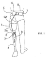
- FIG. 1 is a rear view of a user wearing a drive unit for a prosthetic limb, which includes a Stirling engine, according to an embodiment of the present invention.
- FIG. 2 is a vertical sectional view of the Stirling engine shown in FIG. 1.
- FIG. 1 is a rear view of a user wearing a drive unit for a prosthetic limb, which includes a Stirling engine, according to an embodiment of the present invention
- FIG. 2 is a vertical sectional side view of the Stirling engine shown in FIG. 1.
- reference character E designates a Stirling engine of the present invention, which is typically used for driving a prosthetic leg 1.
- the prosthetic leg 1 includes a thigh portion 2 integrated with a socket 2a in which a user's remaining thigh portion is to be inserted; a shank portion 4 bendably/stretchably connected to a lower end of the thigh portion 2 via a joint 3; and a foot portion 5 connected to a lower end of the shank portion 4.
- the Stirling engine E includes a displacer unit 6 and a control unit 7, which are mounted on a belt B worn around a user' waist portion; a power cylinder unit 8 mounted between the thigh portion 2 and the shank portion 4 of the prosthetic leg 1; and a flexible pressure conduit 22 for transmitting a pressure generated in the displacer unit 6 to the power cylinder unit 8.
- a configuration of the Stirling engine E will be more fully described with reference to FIG. 2.
- the displacer unit 6 includes a displacer cylinder 10; a displacer piston 13 slidably inserted in the cylinder 10 so as to partition the interior of the cylinder 10 into an expansion chamber 11 on a head side of the cylinder 10 and a compression chamber 12 on a bottom side of the cylinder 10; a heating device 14, provided around the head portion of the displacer cylinder 10, for heating the expansion chamber 11; a radiator 15, provided on the bottom portion of the displacer cylinder 10, for cooling the compression chamber 12; a heat regenerator 17 interposed in a communication port 16 for connecting the expansion chamber 11 to the compression chamber 12; and a motor-driven control actuator 20 for driving the displacer piston 13 via a rod 18 passing through the bottom portion of the displacer cylinder 10.
- a displacer piston sensor 21 for detecting a position of the displacer piston 13 is provided on the control actuator 20.
- the heating device 14 is of a catalyst type in which a combustion housing 25 formed on an outer surface of the head portion of the displacer cylinder 10 is filled with an oxidation catalyst 26.
- a fuel-air mixer 27 is provided at one end portion of the combustion housing 25, and an exhaust pipe 28 is provided at the other end of the housing 25.
- the catalyst 26 is also supported by an outer surface of the head portion of the displacer cylinder 10 in the combustion cylinder 25.
- the fuel-air mixer 27 has a fuel port 27b and an air port 27a adjacent to each other.
- the displacer cylinder 10, the radiator 15, and the combustion housing 25 are covered with a shroud 30.
- the shroud 30 has an air introduction port 31a at a position near the radiator 15 and a fuel introduction port 32a at a position near the exhaust pipe 28.
- a first partition wall 29a for surrounding the combustion housing 25 and a second partition wall 29b for surrounding the first partition wall 29a are disposed in the shroud 30. With these partition walls 29a and 29b and the shroud 30, an air passage 31 for communicating the air introduction port 31a to the air port 27a while meandering therebetween is partitioned from a fuel passage 32 for communicating the fuel introduction port 32a to the fuel port 27b along an outer periphery of the combustion housing 25.
- a radiator 36 is additionally provided on an outer peripheral surface of the exhaust pipe 28 in such a manner as to face to the fuel passage 32.
- a solid electrolyte device 33 is additionally provided on the first partition wall 29a.
- the solid electrolyte device 33 generates a power with an air pole 33a thereof facing to the air passage 31 and a fuel pole 33b thereof facing to the fuel passage 32.
- a thermal-electric converting device 34 is additionally provided on an outer peripheral surface of the exhaust pipe 28. The thermal-electric converting device 34 converts heat transferred from the exhaust pipe 28 thereto into electricity, to thus generate a power. An output from the thermal-electrical converting device 34 is charged in a storage battery 39 to be described later.
- a supporting wall 35 for containing the control actuator 20 while supporting a fixed portion of the actuator 20 is provided in such a manner as to be continuous to the shroud 30.
- the control unit 7 includes an electronic control unit 37, a fuel cartridge 38, the storage battery 39 as a power source for the electronic control unit 37, and a manually operated controller 40 for arbitrarily operating the electronic control unit 37.
- the electronic control unit 37, the fuel cartridge 38, and the storage battery 39 are contained in a control box 41.
- the fuel cartridge 38 is filled with a fuel such as butane.
- the fuel cartridge 38 is connected to the fuel introduction port 32a via a fuel conduit 42, and a fuel adjuster 44 for adjusting a flow rate of fuel is interposed in the fuel conduct 42.
- An ignition plug 45 is provided in the combustion housing 25 at a position adjacent to the mixer 27.
- the power cylinder unit 8 includes a power cylinder 47 pivotably connected to one of the thigh portion 2 and the shank portion 4, and a power piston 48 pivotably connected to the other of the thigh portion 2 and the shank portion 4 while slidably inserted in the power cylinder 47.
- An operation chamber 49 defined in the power cylinder 47 by means of the power piston 48 is communicated to the compression chamber 12 of the displacer unit 6.
- a bending/stretching angle sensor 51 for detecting a bending/stretching angle between the thigh portion 2 and the shank portion 4 is mounted at a position between the thigh portion 2 and the shank portion 4.
- An output signal from the bending/stretching angle sensor 51 and output signals from the manually operated controller 40 and the displacer piston sensor 21 are inputted in the electronic control unit 37.
- the electronic control unit 37 controls the actuator 20 and the fuel adjuster 44.
- a fuel is fed from the fuel cartridge 38.
- the flow rate of the fuel is adjusted by the fuel adjuster 44.
- the fuel is then supplied to the fuel-air mixer 27 via the fuel passage 32, to be mixed with air which has flown from the air introduction port 31a into the fuel-air mixer 27 via the air passage 31.
- the fuel-air mixture is ignited once by the ignition plug 45, and thereafter, the combustion of the fuel-air mixture is continuously accelerated by the catalyst 26, to heat the expansion chamber 11 from the head portion side of the displacer cylinder 10 at a specific high temperature.
- An exhaust gas generated by the combustion is discharged to the outside through the exhaust pipe 28.
- heat radiated from the combustion housing 25 and the radiator 36 preheats a fuel gas passing through the fuel passage 32, thereby contributing to acceleration of both electrolytic power generation by the solid electrolyte device 33 and combustion in the combustion housing 25.
- the radiator 15 keeps the compression chamber 12 in a specific low temperature state.
- the heat regenerator 17 receives heat from a working gas which is moving between the expansion chamber 11 and the compression chamber 12 via the communication port 16.
- the control actuator 20 is operated on the basis of a command from the electronic control unit 37, to reciprocate the displacer piston 13, thereby generating a pressure amplitude in the compression chamber 12.
- the pressure is transmitted to the operation chamber 49 of the power cylinder 47 via the flexible pressure conduit 22, to reciprocate the power piston 48, thereby bending/stretching the shank portion 4 relative to the thigh portion 2.
- the bending/stretching motion of the shank portion 2 relative to the thigh portion 4 assists walking of the user.
- the electronic control unit 37 identifies a position of the power piston 48 on the basis of an output signal from the bending/stretching angle sensor 51, and operates the control actuator 20 such that the displacer piston 13 is in advance of the power piston 48 by a converted crank angle of 90°. Further, the electronic control units 37 may controls the operational speed of the displacer piston 13 from zero to an arbitrary value so as to control the bending/stretching speed of the shank portion 4 relative to the thigh portion 2 from zero to an arbitrary value. With this configuration, the prosthetic leg 1 can be moved on the basis of the user's intention.
- the combustion form by the catalyst type heating device 14 is continuous combustion which is stable even in a control state with a relatively small quantity of heat, so that it is possible to enhance the property of an exhaust gas and eliminate occurrence of combustion oscillation. Further, since the fuel cartridge 38 is adopted, it is possible to rapidly supplement a fuel and also to stably heat the expansion chamber 11 of the displacer cylinder 10 for a long-time. This makes it possible to assist walking of the user with comfort for a long time by long-time operation of the small-sized Stirling engine E.
- the thermal transfer from the catalyst 26 to the head portion of the displacer cylinder 10 can be improved. Accordingly, it is possible to enhance a thermal efficiency and hence to contribute to reduction in fuel consumption.
- the power cylinder unit 8 Since only the power cylinder unit 8 is provided on the prosthetic leg 1 while the relatively heavy displacer unit 6, the fuel cartridge 38, the electronic control unit 37, etc. are mounted on the belt B worn around the user's waist portion, and the displacer unit 6 is connected to the power cylinder unit 8 via the flexible pressure conduit 22, it is possible to make the prosthetic leg 1 lightweight and slim while ensuring the smooth bending/stretching motion of the prosthetic leg 1, and further it is possible for the user to easily, rapidly, and simply mount/dismount the displacer unit 6 by mounting/dismounting the belt B around the waist portion.
- the heating device of the present invention can be also applied to an ⁇ -type Stirling engine and to an external combustion engine other than the Stirling engine.
- the invention provides a heating device for an external combustion engine, which is capable of improving stabilization of combustion in a control state with a relatively small quantity of heat and the property of an exhaust gas, and realizing long-time operation of the external combustion engine.
- a heating device 14 for an external combustion engine includes: a combustion housing 25 provided so as to surround a heating portion 11 of an external combustion engine E; an fuel-air mixer 27 provided at one end of the combustion housing 25 and an exhaust pipe 28 provided at the other end of the combustion housing 25; and an oxidation catalyst 26, disposed in the combustion housing 25, for accelerating combustion of a fuel-air mixture of a fuel and air supplied through the fuel-air mixer 27.
Landscapes
- Engineering & Computer Science (AREA)
- Chemical & Material Sciences (AREA)
- Combustion & Propulsion (AREA)
- Mechanical Engineering (AREA)
- General Engineering & Computer Science (AREA)
- Exhaust Gas After Treatment (AREA)
- Thermotherapy And Cooling Therapy Devices (AREA)
Abstract
Description
Claims (3)
- A heating device for an external combustion engine, characterized by including:a combustion housing (25) provided so as to surround a heating portion (11) of an external combustion engine (E) ;an fuel-air mixer (27) provided at one end of said combustion housing (25) and an exhaust pipe (28) provided at the other end of said combustion housing (25); andan oxidation catalyst (26), disposed in said combustion housing (25), for accelerating combustion of a fuel-air mixture of a fuel and air supplied through said fuel-air mixer (27).
- A heating device for an external combustion engine according to claim 1, wherein said oxidation catalyst (26) is supported by an outer surface of said heating portion (11) disposed in said combustion housing (25).
- A heating device for an external combustion engine according to claim 1, wherein said external combustion engine is taken as a Stirling engine (E).
Applications Claiming Priority (4)
| Application Number | Priority Date | Filing Date | Title |
|---|---|---|---|
| JP2001019120 | 2001-01-26 | ||
| JP2001019120A JP4384822B2 (en) | 2001-01-26 | 2001-01-26 | Prosthetic limb drive |
| JP2001020637 | 2001-01-29 | ||
| JP2001020637A JP2002221088A (en) | 2001-01-29 | 2001-01-29 | External combustion engine heating device |
Publications (3)
| Publication Number | Publication Date |
|---|---|
| EP1227238A2 true EP1227238A2 (en) | 2002-07-31 |
| EP1227238A3 EP1227238A3 (en) | 2003-05-02 |
| EP1227238B1 EP1227238B1 (en) | 2007-09-19 |
Family
ID=26608380
Family Applications (1)
| Application Number | Title | Priority Date | Filing Date |
|---|---|---|---|
| EP20010130436 Expired - Lifetime EP1227238B1 (en) | 2001-01-26 | 2001-12-20 | Heating device for external combustion engine |
Country Status (2)
| Country | Link |
|---|---|
| EP (1) | EP1227238B1 (en) |
| DE (1) | DE60130535T2 (en) |
Family Cites Families (1)
| Publication number | Priority date | Publication date | Assignee | Title |
|---|---|---|---|---|
| JPH08296501A (en) * | 1995-03-02 | 1996-11-12 | Aisin Seiki Co Ltd | Stirling engine heater |
-
2001
- 2001-12-20 DE DE2001630535 patent/DE60130535T2/en not_active Expired - Fee Related
- 2001-12-20 EP EP20010130436 patent/EP1227238B1/en not_active Expired - Lifetime
Also Published As
| Publication number | Publication date |
|---|---|
| DE60130535T2 (en) | 2008-01-31 |
| EP1227238B1 (en) | 2007-09-19 |
| DE60130535D1 (en) | 2007-10-31 |
| EP1227238A3 (en) | 2003-05-02 |
Similar Documents
| Publication | Publication Date | Title |
|---|---|---|
| US6645252B2 (en) | Drive unit for prosthetic limb | |
| US6910331B2 (en) | Stirling engine | |
| JP2002219141A5 (en) | ||
| US7082909B2 (en) | Free-piston device with electric linear drive | |
| JP4248303B2 (en) | Power unit comprising a combustion engine and a Stirling engine | |
| JP2007527478A (en) | Recuperator and combustor used for external combustion engine, and power generation system using them | |
| US20040221576A1 (en) | Thermal cycle engine boost bridge power interface | |
| US6543216B2 (en) | Heating device for external combustion engine | |
| JP3692506B2 (en) | Free piston regenerative Stirling engine | |
| EP1227238B1 (en) | Heating device for external combustion engine | |
| EP1241339A2 (en) | Compound-type energy generation system | |
| JP2763173B2 (en) | Portable power supply | |
| US20100327587A1 (en) | Fuel gas generator | |
| US7028473B2 (en) | Hot-gas engine | |
| JP2010112241A (en) | Stirling engine | |
| US7607299B2 (en) | Thermal cycle engine with augmented thermal energy input area | |
| JP2002276464A (en) | Stirling engine control device | |
| JP2002276463A (en) | Stirling engine | |
| FI114113B (en) | External internal combustion engine | |
| SU826061A1 (en) | Heat outer-supply engine | |
| US20080134676A1 (en) | Power structure for a power-saving engine | |
| JP2005188402A (en) | Energy recovery device for internal combustion engine | |
| RU97104669A (en) | METHOD OF CONTROL OF HEAT MACHINE |
Legal Events
| Date | Code | Title | Description |
|---|---|---|---|
| PUAI | Public reference made under article 153(3) epc to a published international application that has entered the european phase |
Free format text: ORIGINAL CODE: 0009012 |
|
| AK | Designated contracting states |
Kind code of ref document: A2 Designated state(s): AT BE CH CY DE DK ES FI FR GB GR IE IT LI LU MC NL PT SE TR |
|
| AX | Request for extension of the european patent |
Free format text: AL;LT;LV;MK;RO;SI |
|
| PUAL | Search report despatched |
Free format text: ORIGINAL CODE: 0009013 |
|
| AK | Designated contracting states |
Designated state(s): AT BE CH CY DE DK ES FI FR GB GR IE IT LI LU MC NL PT SE TR |
|
| AX | Request for extension of the european patent |
Extension state: AL LT LV MK RO SI |
|
| RIC1 | Information provided on ipc code assigned before grant |
Ipc: 7F 02G 1/055 A Ipc: 7A 61F 2/76 B |
|
| 17P | Request for examination filed |
Effective date: 20030716 |
|
| AKX | Designation fees paid |
Designated state(s): DE FR GB IT NL |
|
| 17Q | First examination report despatched |
Effective date: 20061129 |
|
| GRAP | Despatch of communication of intention to grant a patent |
Free format text: ORIGINAL CODE: EPIDOSNIGR1 |
|
| GRAS | Grant fee paid |
Free format text: ORIGINAL CODE: EPIDOSNIGR3 |
|
| GRAA | (expected) grant |
Free format text: ORIGINAL CODE: 0009210 |
|
| AK | Designated contracting states |
Kind code of ref document: B1 Designated state(s): DE FR GB IT NL |
|
| REG | Reference to a national code |
Ref country code: GB Ref legal event code: FG4D |
|
| REF | Corresponds to: |
Ref document number: 60130535 Country of ref document: DE Date of ref document: 20071031 Kind code of ref document: P |
|
| NLV1 | Nl: lapsed or annulled due to failure to fulfill the requirements of art. 29p and 29m of the patents act | ||
| ET | Fr: translation filed | ||
| PG25 | Lapsed in a contracting state [announced via postgrant information from national office to epo] |
Ref country code: NL Free format text: LAPSE BECAUSE OF FAILURE TO SUBMIT A TRANSLATION OF THE DESCRIPTION OR TO PAY THE FEE WITHIN THE PRESCRIBED TIME-LIMIT Effective date: 20070919 |
|
| PLBE | No opposition filed within time limit |
Free format text: ORIGINAL CODE: 0009261 |
|
| STAA | Information on the status of an ep patent application or granted ep patent |
Free format text: STATUS: NO OPPOSITION FILED WITHIN TIME LIMIT |
|
| 26N | No opposition filed |
Effective date: 20080620 |
|
| GBPC | Gb: european patent ceased through non-payment of renewal fee |
Effective date: 20071220 |
|
| PG25 | Lapsed in a contracting state [announced via postgrant information from national office to epo] |
Ref country code: GB Free format text: LAPSE BECAUSE OF NON-PAYMENT OF DUE FEES Effective date: 20071220 |
|
| PGFP | Annual fee paid to national office [announced via postgrant information from national office to epo] |
Ref country code: IT Payment date: 20081220 Year of fee payment: 8 |
|
| PGFP | Annual fee paid to national office [announced via postgrant information from national office to epo] |
Ref country code: FR Payment date: 20081212 Year of fee payment: 8 |
|
| PGFP | Annual fee paid to national office [announced via postgrant information from national office to epo] |
Ref country code: DE Payment date: 20081219 Year of fee payment: 8 |
|
| REG | Reference to a national code |
Ref country code: FR Ref legal event code: ST Effective date: 20100831 |
|
| PG25 | Lapsed in a contracting state [announced via postgrant information from national office to epo] |
Ref country code: FR Free format text: LAPSE BECAUSE OF NON-PAYMENT OF DUE FEES Effective date: 20091231 |
|
| PG25 | Lapsed in a contracting state [announced via postgrant information from national office to epo] |
Ref country code: DE Free format text: LAPSE BECAUSE OF NON-PAYMENT OF DUE FEES Effective date: 20100701 |
|
| PG25 | Lapsed in a contracting state [announced via postgrant information from national office to epo] |
Ref country code: IT Free format text: LAPSE BECAUSE OF NON-PAYMENT OF DUE FEES Effective date: 20091220 |